
Related Manuals for SIGMATEK S-DIAS AI 022


Summary of Contents for SIGMATEK S-DIAS AI 022
- Page 1 AI 022 S-DIAS Strain Gauge Input Module Operating Manual Date of creation: 20.09.2013 Version date: 04.11.2020 Article number: 20-009-022-E...
- Page 2 (print, photocopy, microfilm or in any other process) without the express permission. We reserve the right to make changes in the content without notice. The SIGMATEK GmbH & Co KG is not responsible for technical or printing errors in the handbook and assumes no responsibility for damages that occur through use...
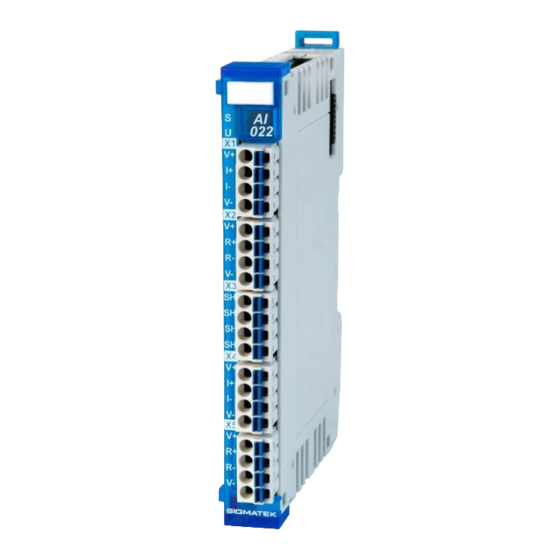
- Page 3 S-DIAS Strain Gauge Input Module AI 022 with 2 analog inputs The S-DIAS AI 022 strain gauge input module is used to analyze meas- uring bridges (e.g. strain gauge load cells) With a 24-bit resolution, measurement values with an overall accuracy of 0.035 % are provided.
-
Page 4: Table Of Contents
AI 022 S-DIAS STRAIN GAUGE INPUT MODULE Contents Technical Data ................ 4 Analog Channel Specifications ........... 4 Electrical Requirements ............... 5 Miscellaneous ................7 Environmental Conditions ............7 Mechanical Dimensions ............8 Connector Layout ..............9 Status LEDs ................. 10 Applicable Connectors ............... - Page 5 S-DIAS STRAIN GAUGE INPUT MODULE AI 022 General ..................22 Analog Inputs ................23 Communication Interfaces ............24 Setting the Filter Depth .............. 25 Setting the Force Measurement Sensor: ........25 Example ..................26 04.11.2020 Page 3...
-
Page 6: Technical Data
AI 022 S-DIAS STRAIN GAUGE INPUT MODULE Technical Data Analog Channel Specifications Number of channels Bridge supply voltage +5 V Load cell rated values 0.25 mV/V 0.5 mV/V 1 mV/V 2 mV/V 16 mV/V Measurement range ±1.875 mV ±3.75 mV ±7.5 mV ±15 mV ±120 mV... -
Page 7: Electrical Requirements
S-DIAS STRAIN GAUGE INPUT MODULE AI 022 Electrical Requirements Voltage supply from S-DIAS bus +5 V Current consumption on the typically 50 mA maximum 55 mA S-DIAS bus (+5 V power supply) Voltage supply from S-DIAS bus +24 V Current consumption on the typically 17 mA at +18 V maximum 20 mA at +18 V S-DIAS bus (+24 V power sup-... - Page 8 AI 022 S-DIAS STRAIN GAUGE INPUT MODULE Page 6 04.11.2020...
-
Page 9: Miscellaneous
S-DIAS STRAIN GAUGE INPUT MODULE AI 022 Miscellaneous Article number 20-009-022 Hardware version Standard UL 508 (E247993) Approvals UL, cUL, CE Environmental Conditions Storage temperature -20 ... +85 °C Environmental temperature 0 ... +60 °C Humidity 0-95 %, non-condensing Installation altitude above sea 0-2000 m without derating level >... -
Page 10: Mechanical Dimensions
AI 022 S-DIAS STRAIN GAUGE INPUT MODULE Mechanical Dimensions Page 8 04.11.2020... -
Page 11: Connector Layout
S-DIAS STRAIN GAUGE INPUT MODULE AI 022 Connector Layout 04.11.2020 Page 9... -
Page 12: Status Leds
AI 022 S-DIAS STRAIN GAUGE INPUT MODULE Status LEDs Module Status green module active no supply available BLINKING (5 Hz) no communication User yellow can be set from the application (e.g. the module LED can be set to blinking through the visual- ization so that the module is easily found in the control cabinet) BLINKING (2 Hz) BLINKING (4 Hz) -
Page 13: Label Field
S-DIAS STRAIN GAUGE INPUT MODULE AI 022 Label Field Manufacturer Weidmüller Type MF 10/5 CABUR MC NE WS Weidmüller article number 1854510000 Compatible printer Weidmüller Type Printjet Advanced 230V Weidmüller article number 1324380000 04.11.2020 Page 11... -
Page 14: Wiring
AI 022 S-DIAS STRAIN GAUGE INPUT MODULE Wiring Wiring Example Page 12 04.11.2020... -
Page 15: Notes
S-DIAS STRAIN GAUGE INPUT MODULE AI 022 Notes The signals recorded by the analog modules are very small, as compared to the digital sig- nals. To ensure error-free operation, a careful wiring method must be followed: The DIN rail must have an adequate ground connection. •... -
Page 16: Connection Variants
AI 022 S-DIAS STRAIN GAUGE INPUT MODULE Connection Variants Two connection Types can be used when measuring with strain gauges: 4-wire measurement: The advantage of this variant is that a 4-pin connector cable can be used for the strain gauge. The voltage drop on over the circuit for the bridge voltage supply, however, cannot be compensated. -
Page 17: Mounting
S-DIAS STRAIN GAUGE INPUT MODULE AI 022 Mounting The S-DIAS modules are designed for installation into the control cabinet. To mount the mod- ules a DIN-rail is required. The DIN rail must establish a conductive connection with the back wall of the control cabinet. The individual S-DIAS modules are mounted on the DIN rail as a block and secured with latches. - Page 18 AI 022 S-DIAS STRAIN GAUGE INPUT MODULE Recommended minimum distances of the S-DIAS modules to the surrounding components or control cabinet wall: a, b, c … distances in mm (inches) Page 16 04.11.2020...
-
Page 19: Addressing
S-DIAS STRAIN GAUGE INPUT MODULE AI 022 Addressing Address Mapping Overview Address Size Access Type Description (hex) (bytes) 0000 Cyclic Data for Firmware 0000 0080 Cyclic Data for the HW Class Status Bit 0 not used Bit 1 no SYNC Bit 2 FLASH data CRC error Bit 3... - Page 20 AI 022 S-DIAS STRAIN GAUGE INPUT MODULE Standard Mode (info-register bit 0 = 0) CFG data for ADC 1 Bit 0-9 filter limit frequency 0106 Bit 10 SINC Bit 11-13 mode CFG data for ADC 1 0108 Bit 0-2 Gain CFG data for ADC 2 Bit 0-9 filter limit frequency...
-
Page 21: Address Mapping Overview - Factory Calibration
S-DIAS STRAIN GAUGE INPUT MODULE AI 022 Address Mapping Overview – Factory Calibration The factory calibration data are in the FLASH of the µC at a defined address. With the intelligent SDO access “CMD 18” with the “SubCMD 3” for reading the internal con- figuration memory and the offset information 0x20 this Flash memory area of the module can be accessed directly (since FW 01.80). -
Page 22: Supported Cycle Times
AI 022 S-DIAS STRAIN GAUGE INPUT MODULE Supported Cycle Times Cycle Times below 1 ms (in µs) V3.00 Cycle Times equal to or higher than 1 ms (in ms) V3.00 V3.00 Page 20 04.11.2020... -
Page 23: Hardware Class Ai022
S-DIAS STRAIN GAUGE INPUT MODULE AI 022 Hardware Class AI022 Hardware class AI022 for the S-DIAS AI022 analog module This hardware class is used to control the AI 022 hardware module. The module has two analog inputs for resistance bridges (e.g. DMS load cells). More information on the hardware can be found in the module documentation. -
Page 24: General
AI 022 S-DIAS STRAIN GAUGE INPUT MODULE General State This server shows the actual status of the hardware class. Class State State The device ID of the hardware module is shown in this server. Device ID State FPGA version of the module in 16#XY (e.g. 16#10 = version 1.0). FPGA Version State Hardware version of the module in format 16#XXYY (e.g. -
Page 25: Analog Inputs
S-DIAS STRAIN GAUGE INPUT MODULE AI 022 Analog Inputs State ADC configura- the configuration of the ADCs is valid => the analog values can tion valid be used in the application the configuration of the ADCs is invalid error while sending the configuration to the ADCs Input Current value of the respective analog channel (if AI[1-2]ConfigValid, as well Analog Input [1-... -
Page 26: Communication Interfaces
AI 022 S-DIAS STRAIN GAUGE INPUT MODULE Output Reset to Fac- function not available (available starting with FW version 1.80) tory Settings invalid CRC in the factory settings invalid input parameters (must be 1, 2 or 3) reset successful, if ConfigValid goes to 1 State Shows, whether the ADC for the according channel is set to factory settings. -
Page 27: Setting The Filter Depth
S-DIAS STRAIN GAUGE INPUT MODULE AI 022 Setting the Filter Depth When setting the filter depth, it is important to ensure that the conversion time is dependent on it. Calculating the ADC data rate f (with f = 4.92 MHz) for the sinc 4 filter: /(4 * 1024 * AI[1-2]FilterDepth) Calculating the ADC data rate f (with f... -
Page 28: Example
AI 022 S-DIAS STRAIN GAUGE INPUT MODULE Example Page 26 04.11.2020... - Page 29 S-DIAS STRAIN GAUGE INPUT MODULE AI 022 Documentation Changes Change date Affected Chapter Note page(s) 26.09.2013 Updated complete chapter (values and description) Status AI1/AI2: changed from ON to BLINKING (3 Address 0080: changed Bit0 from 24V DC not OK to not used 04.10.2013 Note...
- Page 30 AI 022 S-DIAS STRAIN GAUGE INPUT MODULE 01.03.2017 1.1 Analog Channel Specifi- Hardware filter added cations 27.03.2017 1.1 Analog Channel Specifi- Added value for sensor break detection cations 17.08.2017 1.4 Environmental Conditions Added operating conditions 3.2 Applicable Connectors Added sleeve length Added info regarding ultrasonically welded strands 18.10.2017 3.3 Label Field...
Need help?
Do you have a question about the S-DIAS AI 022 and is the answer not in the manual?
Questions and answers