
Related Manuals for SIGMATEK SR 022


Summary of Contents for SIGMATEK SR 022
- Page 1 SR 022 S-DIAS Current Controller Module Instruction Manual Date of creation: 06.06.2017 Version date: 26.07.2023 Article number: 20-029-022-E...
- Page 2 (print, photocopy, microfilm or in any other process) without the express permission. We reserve the right to make changes in the content without notice. The SIGMATEK GmbH & Co KG is not responsi- ble for technical or printing errors in the handbook and assumes no responsibility for damages that occur through...
- Page 3 1 digital input +5 V 2 digital inputs +24 V The S-DIAS SR 022 current controller module is used to operate a DC motor with a 12-30 V supply voltage and a maximum motor current of 3.5 A. Higher starting currents are possible for a short period.
-
Page 4: Table Of Contents
SR 022 S-DIAS CURRENT CONTROLLER MODULE Contents Introduction ................4 Target Group/Purpose of this Operating Manual ...... 4 Important Reference Documentation ......... 4 Contents of Delivery ..............4 Basic Safety Directives ............5 Symbols Used ................5 Disclaimer ..................7 General Safety Directives ............ - Page 5 S-DIAS CURRENT CONTROLLER MODULE SR 022 Mechanical Dimensions ............18 Connector Layout ..............19 Status LEDs ................. 20 Applicable Connectors ............... 21 Label Field ................... 22 Wiring ..................23 Wiring Example ................23 Note ....................24 Assembly/Installation ............25 Check Contents of Delivery ............25 Mounting ..................
-
Page 6: Introduction
General knowledge of automation technology is required. Further help and training information, as well as the appropriate accessories can be found on our website www.sigmatek-automation.com. Our support team is happily available to answer your questions. Please see our website for our hotline number and business hours. -
Page 7: Basic Safety Directives
S-DIAS CURRENT CONTROLLER MODULE SR 022 Basic Safety Directives Symbols Used The following symbols are used in the operator documentation for warning and danger messages, as well as informational notes: DANGER Danger indicates that death or serious injury will occur, if the speci- fied measures are not taken. - Page 8 SR 022 S-DIAS CURRENT CONTROLLER MODULE WARNING Hot Surfaces Surfaces chaudes INFORMATION Information Provides important information on the product, handling or relevant sections of the documentation, which require atten- tion. Page 6 26.07.2023...
-
Page 9: Disclaimer
It does not guarantee properties under the warranty. Please thoroughly read the corresponding documents and this operat- ing manual before handling a product. SIGMATEK GmbH & Co KG is not liable for damages caused through, non-compliance with these instructions or applicable regulations. -
Page 10: General Safety Directives
SR 022 S-DIAS CURRENT CONTROLLER MODULE General Safety Directives The Safety Directives in the other sections of this operating manual must be observed. These instructions are visually emphasized by symbols. INFORMATION According to EU Directives, the operating manual is a component of a product. -
Page 11: Software/Training
S-DIAS CURRENT CONTROLLER MODULE SR 022 CAUTION Handle the device with care and do not drop or let fall. Prevent foreign bodies and fluids from entering the device. The device must not be opened! Manipulez l’appareil avec précaution et ne le laissez pas tomber. -
Page 12: Standards And Directives
The product was constructed in compliance with the following European Union directives and tested for conformity. 3.1.1 EU Conformity Declaration EU Declaration of Conformity The product SR 022 conforms to the following European directives: • 2014/35/EU Low-voltage Directive • 2014/30/EU Electromagnetic Compatibility (EMC Directive) •... -
Page 13: Type Plate
S-DIAS CURRENT CONTROLLER MODULE SR 022 Type Plate HW: Hardware version SW: Software version 26.07.2023 Page 11... -
Page 14: Technical Data
SR 022 S-DIAS CURRENT CONTROLLER MODULE Technical Data Motor Output Specifications Number Supply voltage 12-30 V DC Controller frequency 30 kHz Current 0-2.0 A in S1 mode 0-3.5 A in S3 mode Output current over the envi- 2.0 A (S1)/3.5 A (S3) up to 45 °C ronmental temperature 1.0 A (S1)/1.4 A (S3) up to 55 °C... -
Page 15: Incremental Encoder Input Specifications
S-DIAS CURRENT CONTROLLER MODULE SR 022 Incremental Encoder Input Specifications Number Input signals Incremental encoder signals RS422 (A, /A, B, /B, R, /R) RS422 signal (120 termination, integrated in module) Incremental encoder signals TTL (A, B, R) TTL level (1200 Pull-Up, integrated in module) -
Page 16: Digital Input Specifications
SR 022 S-DIAS CURRENT CONTROLLER MODULE +5 V Digital Input Specifications Number Input voltage typically +5 V maximum +5.5 V Signal level low: < +0.8 V High: > +2.0 V Switching threshold typically +1.4 V Input current 1.5 mA at +5 V... - Page 17 S-DIAS CURRENT CONTROLLER MODULE SR 022 INFORMATION If this S-DIAS module is connected to an S-DIAS supply module with several S-DIAS modules, the total current of the modules used must be determined and checked. The total current of the +24 V supply cannot exceed 1.6 A! The total current of the +5 V supply cannot exceed 1.6 A!
- Page 18 SR 022 S-DIAS CURRENT CONTROLLER MODULE Page 16 26.07.2023...
-
Page 19: Miscellaneous
S-DIAS CURRENT CONTROLLER MODULE SR 022 Miscellaneous Article number 20-029-022 Standard designed according to UL Approbations cUL, CE in preparation, UKCA Environmental Conditions Storage temperature -20... +85 °C Environmental temperature 0... +55 °C Humidity 0-95 %, non-condensing Installation altitude above sea... -
Page 20: Mechanical Dimensions
SR 022 S-DIAS CURRENT CONTROLLER MODULE Mechanical Dimensions Page 18 26.07.2023... -
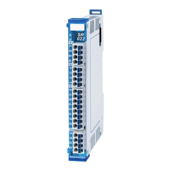
Page 21: Connector Layout
S-DIAS CURRENT CONTROLLER MODULE SR 022 Connector Layout INFORMATION The connections of the +24 V supply (X4: pin 1 and pin 2) or the GND supply (X4: pin 3 and pin 4) are internally bridged. To supply the mod- ule, only one connection to a +24 V pin (pin 1 or pin 2) and a GND pin (pin 3 or pin 4) is required. -
Page 22: Status Leds
SR 022 S-DIAS CURRENT CONTROLLER MODULE Status LEDs Module Status green module active no supply available BLINKING (5 Hz) no communication User yellow can be set from the application (e.g. the module LED can be set to blinking through the visuali-... -
Page 23: Applicable Connectors
S-DIAS CURRENT CONTROLLER MODULE SR 022 Applicable Connectors Connectors: X1-X4: Connectors with spring terminals (included in delivery) The spring terminals are suitable connecting ultrasonically compacted (ultrasonically weld- ed) strands. Connections: Stripping length/Sleeve length: 10 mm Mating direction: parallel to the conductor axis or circuit board Conductor cross section rigid: 0.2-1.5 mm... -
Page 24: Label Field
SR 022 S-DIAS CURRENT CONTROLLER MODULE Label Field Manufacturer Weidmüller Type MF 10/5 CABUR MC NE WS Weidmüller article number 1854510000 Compatible printer Weidmüller Type Printjet Advanced 230V Weidmüller article number 1324380000 Page 22 26.07.2023... -
Page 25: Wiring
S-DIAS CURRENT CONTROLLER MODULE SR 022 Wiring Wiring Example 26.07.2023 Page 23... -
Page 26: Note
SR 022 S-DIAS CURRENT CONTROLLER MODULE Note The signals recorded by the analog modules are very small, as compared to the digital signals. To ensure error-free operation, a careful wiring method must be followed: • The DIN rail must have an adequate mass connection. -
Page 27: Assembly/Installation
S-DIAS CURRENT CONTROLLER MODULE SR 022 Assembly/Installation Check Contents of Delivery Ensure that the contents of the delivery are complete and intact. See chapter Contents of Delivery. INFORMATION On receipt and before initial use, check the device for damage. If the device is damaged, contact our customer service and do not install the device in your system. -
Page 28: Mounting
SR 022 S-DIAS CURRENT CONTROLLER MODULE Mounting The S-DIAS modules are designed for installation into the control cabinet. To mount the modules a DIN-rail is required. The DIN rail must establish a conductive connection with the back wall of the control cabinet. The individual S-DIAS modules are mounted on the DIN rail as a block and secured with latches. - Page 29 S-DIAS CURRENT CONTROLLER MODULE SR 022 Recommended minimum distances of the S-DIAS modules to the surrounding components or control cabinet wall: a, b, c … distances in mm (inches) 26.07.2023 Page 27...
-
Page 30: Addressing
SR 022 S-DIAS CURRENT CONTROLLER MODULE 10 Addressing Address Size Access Description Reset (hex) (bytes) Type value Cyclic Writing Control register: Bit 0: Sequence activated (note: bit 1 from the latched status register "False sequence occurred" must '0') Bit 2..1:... - Page 31 S-DIAS CURRENT CONTROLLER MODULE SR 022 Bit 12: null position R1 Bit 13: null position latced (delete when reading) Bit 15..14: Reserved Incremental encoder 000A 0000 Actual counter value incremental encoder latched 000C 0000 Latched counter value 000E T the temperature in °K...
- Page 32 SR 022 S-DIAS CURRENT CONTROLLER MODULE Sequence 1 data. 16 bit values Bit 10..0: Time value / clock frequency Bit 11: 1 = use absolute time counter 0 = use relative time counter 0020 0000 Bit 12: upper left Bit 13:...
-
Page 33: Transport/Storage
S-DIAS CURRENT CONTROLLER MODULE SR 022 11 Transport/Storage INFORMATION This device contains sensitive electronics. During transport and stor- age, high mechanical stress must therefore be avoided. For storage and transport, the same values for humidity and vibration as for operation must be maintained! Temperature and humidity fluctuations may occur during transport. -
Page 34: Maintenance
SR 022 S-DIAS CURRENT CONTROLLER MODULE 13 Maintenance INFORMATION During maintenance as well as servicing, observe the safety instruc- tions from chapter 2 Basic Safety Directives. 13.1 Service This product was constructed for low-maintenance operation. 13.2 Repair INFORMATION In the event of a defect/repair, send the device with a detailed error description to the address listed at the beginning of this document. -
Page 35: Hardware Class Sr022
15 Hardware Class SR022 Hardware Class SR022 for the S-DIAS SR022 module This hardware class is used to control the hardware module SR 022 with 1x DC motor driv- er and 1x incremental encoder (RS422/TTL). More information on the hardware can be found in the module documentation. -
Page 36: General
SR 022 S-DIAS CURRENT CONTROLLER MODULE 15.1 General ClassState State This server shows the actual status of the hardware class. Device ID State The device ID of the hardware module is shown in this server. FPGA version State FPGA version of the module in 16#XY (e.g. 16#10 = version 1.0). -
Page 37: Dc Motor
S-DIAS CURRENT CONTROLLER MODULE SR 022 Error Bits State In this server, the status bits of the FW are shown. The respective bits mean the following: Bit 0 not defined Bit 1 no Sync available Bit 2 FLASH data CRC error... -
Page 38: Incremental Encoder
SR 022 S-DIAS CURRENT CONTROLLER MODULE Min Pulse Output With this server, the minimum pulse width of the PWM can be defined per mil. The server value can be changed over the write() method. A change is not valid before calling the write() method of the server SetSpeed in the control (default: 7). -
Page 39: Communication Interfaces
S-DIAS CURRENT CONTROLLER MODULE SR 022 Digital Input [1- Input Digital Inputs 1-3 Encoder Mode Property Encoder mode. switched off TTL mode (default) RS422 mode as initialization value Encoder Sam- Property Here, the setting for the edge evaluation of the encoder can be defined. - Page 40 SR 022 S-DIAS CURRENT CONTROLLER MODULE Documentation Changes Change date Affected Chapter Note page(s) 17.08.2017 3.2 Applicable Connectors Added sleeve length Added info regarding ultrasonically welded strands 23.08.2017 1.1 Motor Output Specifica- Changed and extended the table content for a more...
Need help?
Do you have a question about the SR 022 and is the answer not in the manual?
Questions and answers