
Subscribe to Our Youtube Channel
Related Manuals for SIGMATEK VI 021


Summary of Contents for SIGMATEK VI 021
- Page 1 VI 021 S-DIAS VARAN Control Module Instruction Manual Date of creation: 11.06.2013 Version date: 26.07.2023 Article number: 20-003-021-E...
- Page 2 (print, photocopy, microfilm or in any other process) without the express permission. We reserve the right to make changes in the content without notice. The SIGMATEK GmbH & Co KG is not responsible for technical or printing errors in the handbook and assumes no responsibility for damages that occur...
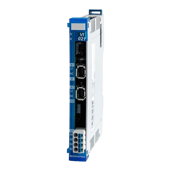
- Page 3 VI 021 1x VARAN In 1x VARAN Out (optional Ethernet (VtE)) The S-DIAS VI 021 module serves as the power supply and connection for decentralized S-DIAS module groups with a CPU over the VARAN bus. A module group consists of a control module and up to 32 connected S- DIAS modules.
-
Page 4: Table Of Contents
VI 021 S-DIAS CONTROL MODULE VARAN Contents Introduction ................5 Target Group/Purpose of this Operating Manual ...... 5 Important Reference Documentation ......... 5 Contents of Delivery ..............5 Basic Safety Directives ............6 Symbols Used ................6 Disclaimer ..................8 General Safety Directives ............ - Page 5 S-DIAS CONTROL MODULE VARAN VI 021 Status LEDs ................. 18 Connectors .................. 18 Applicable Connector Cables ............ 19 Applicable Connectors ............... 20 Label Field ................... 21 Strain Relief ................22 Assembly/Installation ............23 Check Contents of Delivery ............23 Mounting ..................24 10 Recommended Shielding for VARAN ........
- Page 6 VI 021 S-DIAS CONTROL MODULE VARAN 11.4.3 CIV Transparent ................38 12 Transport/Storage ..............39 13 Storage ...................39 14 Maintenance ................40 14.1 Service ..................40 14.2 Repair ................... 40 15 Disposal ..................40 Page 4 26.07.2023...
-
Page 7: Introduction
General knowledge of automation technology is required. Further help and training information, as well as the appropriate accessories can be found on our website www.sigmatek-automation.com. Our support team is happily available to answer your questions. Please see our website for our hotline number and business hours. -
Page 8: Basic Safety Directives
VI 021 S-DIAS CONTROL MODULE VARAN Basic Safety Directives Symbols Used The following symbols are used in the operator documentation for warning and danger messages, as well as informational notes: DANGER Danger indicates that death or serious injury will occur, if the specified measures are not taken. - Page 9 S-DIAS CONTROL MODULE VARAN VI 021 INFORMATION Information Provides important information on the product, handling or relevant sections of the documentation, which require attention. 26.07.2023 Page 7...
-
Page 10: Disclaimer
It does not guarantee properties under the warranty. Please thoroughly read the corresponding documents and this operating manual before handling a product. SIGMATEK GmbH & Co KG is not liable for damages caused through, non-compliance with these instructions or applicable regulations. -
Page 11: General Safety Directives
S-DIAS CONTROL MODULE VARAN VI 021 General Safety Directives The Safety Directives in the other sections of this operating manual must be observed. These instructions are visually emphasized by symbols. INFORMATION According to EU Directives, the operating manual is a component of a product. -
Page 12: Software/Training
VI 021 S-DIAS CONTROL MODULE VARAN CAUTION Handle the device with care and do not drop or let fall. Prevent foreign bodies and fluids from entering the device. The device must not be opened! Manipulez l’appareil avec précaution et ne le laissez pas tomber. -
Page 13: Standards And Directives
The product was constructed in compliance with the following European Union directives and tested for conformity. 3.1.1 EU Conformity Declaration EU Declaration of Conformity The product VI 021 conforms to the following European directives: • 2014/35/EU Low-voltage Directive • 2014/30/EU Electromagnetic Compatibility (EMC Directive) •... -
Page 14: Type Plate
VI 021 S-DIAS CONTROL MODULE VARAN Type Plate HW: Hardware version SW: Software version Page 12 26.07.2023... -
Page 15: Technical Data
Current consumption of voltage the current consumption is dependent on the connected loads supply (max. 2.75 A) Voltage supply on the S-DIAS via the VI 021 Current capacity on the S-DIAS +5 V +24 V bus (power supply for I/O/P maximum 1.6 A... - Page 16 VI 021 S-DIAS CONTROL MODULE VARAN Page 14 26.07.2023...
-
Page 17: Miscellaneous
S-DIAS CONTROL MODULE VARAN VI 021 Miscellaneous Article number 20-003-021 20-003-021-X (polymer coated printed circuit board) Standard UL 508 (E247993) Approbations UL, cUL, CE, UKCA Environmental Conditions Storage temperature -20 ... +85 °C Environmental temperature 0 ... +55 °C HW1.x to 3.x Environmental temperature 0 ... -
Page 18: Mechanical Dimensions
VI 021 S-DIAS CONTROL MODULE VARAN Mechanical Dimensions Page 16 26.07.2023... -
Page 19: Connector Layout
S-DIAS CONTROL MODULE VARAN VI 021 Connector Layout INFORMATION The connections of the +24 V supply (X4: pin 1 and pin 2) or the GND supply (X4: pin 3 and pin 4) are internally bridged. To supply the module, only one connection to a +24 V pin (pin 1 or pin 2) and a GND pin (pin 3 or pin 4) is required. -
Page 20: Status Leds
VI 021 S-DIAS CONTROL MODULE VARAN Status LEDs Sync green the module is synchronized with the VARAN manager. Reset the module is in Reset. VARAN In Link green the connection between the two PHYs is established. BLINKS the VARAN In of the primary client does not have a link. -
Page 21: Applicable Connector Cables
S-DIAS CONTROL MODULE VARAN VI 021 Applicable Connector Cables VARAN Cable type Length Article number RJ45 on industrial Mini I/O Type 1, drag chain capable 0.5 m 16-911-005 16-911-010 1.5 m 16-911-015 16-911-020 16-911-030 16-911-050 10 m 16-911-100 20 m... -
Page 22: Applicable Connectors
VI 021 S-DIAS CONTROL MODULE VARAN Applicable Connectors Connectors: X1, X2: Tyco Mini I/O Plug Type 1 Lock Extend Version (not included in delivery) X3: Connector with spring terminals (included in delivery) The spring terminals are suitable connecting ultrasonically compacted (ultrasonically welded) strands. -
Page 23: Label Field
S-DIAS CONTROL MODULE VARAN VI 021 Label Field Manufacturer Weidmüller Type MF 10/5 CABUR MC NE WS Weidmüller article number 1854510000 Compatible printer Weidmüller Type Printjet Advanced 230V Weidmüller article number 1324380000 26.07.2023 Page 21... -
Page 24: Strain Relief
VI 021 S-DIAS CONTROL MODULE VARAN Strain Relief INFORMATION The VARAN cable must be mounted close to the module (e.g. using a clamp)! No mechanical stress can be applied to the connection! Page 22 26.07.2023... -
Page 25: Assembly/Installation
S-DIAS CONTROL MODULE VARAN VI 021 Assembly/Installation Check Contents of Delivery Ensure that the contents of the delivery are complete and intact. See chapter 1.3 Contents of Delivery. INFORMATION On receipt and before initial use, check the device for damage. If the device is damaged, contact our customer service and do not install the device in your system. -
Page 26: Mounting
VI 021 S-DIAS CONTROL MODULE VARAN Mounting The S-DIAS modules are designed for installation into the control cabinet. To mount the modules a DIN-rail is required. The DIN rail must establish a conductive connection with the back wall of the control cabinet. The individual S-DIAS modules are mounted on the DIN rail as a block and secured with latches. - Page 27 S-DIAS CONTROL MODULE VARAN VI 021 Recommended minimum distances of the S-DIAS modules to the surrounding components or control cabinet wall: a, b, c … distances in mm (inches) 26.07.2023 Page 25...
-
Page 28: Recommended Shielding For Varan
It is recommended to avoid placing VARAN bus lines parallel to power cables whenever possible. SIGMATEK recommends the use of CAT5e industrial Ethernet bus cables. For the shielding, an S-FTP cable should be used. -
Page 29: Wiring From The Control Cabinet To An External Varan Component
S-DIAS CONTROL MODULE VARAN VI 021 10.1 Wiring from the Control Cabinet to an External VARAN Component If the Ethernet lines are connected from a VARAN component to a VARAN node located outside the control cabinet, the shielding should be placed at the entry point to the control cabinet housing. -
Page 30: Wiring Outside Of The Control Cabinet
VI 021 S-DIAS CONTROL MODULE VARAN 10.2 Wiring Outside of the Control Cabinet If a VARAN bus line must be connected outside of the control cabinet only, no additional shield support is required. A requirement therefore is, outside the control cabinet, only IP67 modules and connectors are used. -
Page 31: Shielding For Wiring Within The Control Cabinet
S-DIAS CONTROL MODULE VARAN VI 021 10.3 Shielding for Wiring Within the Control Cabinet Sources of strong electromagnetic noise located within the control cabinet (drives, Transformers, etc.) can induce interference in a VARAN bus line. Spike voltages are deflected over the metallic housing of a RJ45 connector. Noise is conducted through the control cabinet housing without further action from the electronic components. -
Page 32: Connecting Noise-Generating Components
VI 021 S-DIAS CONTROL MODULE VARAN 10.4 Connecting Noise-Generating Components With the connection of power components that generate strong electromagnetic interference, it is also critical to ensure correct shielding. The shielding should be placed before a power element (or group of power elements). -
Page 33: Shielding Between Two Control Cabinets
S-DIAS CONTROL MODULE VARAN VI 021 10.5 Shielding Between Two Control Cabinets If two control cabinets must be connected over a VARAN bus, it is recommended that the shielding be located at the entry points of both cabinets. Noise can be thereby stopped from reaching the electronics within the control cabinet. -
Page 34: Hardware Class Vi021
S-DIAS CONTROL MODULE VARAN 11 Hardware Class VI021 VI021 Hardware Class for the S-DIAS VI021 interface module This hardware class is used for controlling the VI 021 hardware module. More information regarding the hardware can be found in the hardware documentation. Page 32... -
Page 35: General
S-DIAS CONTROL MODULE VARAN VI 021 11.1 General State State This server shows the actual status of the hardware class. For a detailed description, see Status of VARAN Hardware Classes. Online State This server is set as soon as the hardware class is processed properly (when the data are valid, drives synchronized,..) The server is reset when an... -
Page 36: Sdias
VI 021 S-DIAS CONTROL MODULE VARAN Serial No Property This client activates the validation of the serial number of a module Validation Serial number of the module is not checked Serial number of the module must be confirmed (validated) The serial number is confirmed for a connected module by writing to the "ValidateSerNo"... -
Page 37: Communication Interfaces
S-DIAS CONTROL MODULE VARAN VI 021 Sdias Manager State On this server, the options supported by the SDIAS Manager are displayed Option Bits bitwise. Bit 1 Interrupts supported Bit 2 Half duplex (SDIAS S2), bus scan required Bit 3 Far Memory access supported... -
Page 38: Transparent Mode
VI 021 S-DIAS CONTROL MODULE VARAN 11.4 Transparent Mode The transparent mode is set so that a project with different stages of the hardware can be maintained with just one software version. Example: With the full range of functions, a system consists of 10 modules that are connected by the VARAN bus. -
Page 39: No Transparent Module
S-DIAS CONTROL MODULE VARAN VI 021 11.4.1 No transparent module The following image shows the output assignment in which no class is set to transparent. The modules are connected to one another by the VARAN bus. 11.4.2 VSV Transparent The "Transparent" client of the VSV hardware class object was initialized with 1. This means that the object is set to transparent. -
Page 40: Civ Transparent
VI 021 S-DIAS CONTROL MODULE VARAN 11.4.3 CIV Transparent The "Transparent" client of the CIV hardware object was initialized with 1. This means that the object is set to transparent. The CIV hardware must therefore be removed from the configuration and the VSV module is connected directly to the following CIV module. -
Page 41: Transport/Storage
S-DIAS CONTROL MODULE VARAN VI 021 12 Transport/Storage INFORMATION This device contains sensitive electronics. During transport and storage, high mechanical stress must therefore be avoided. For storage and transport, the same values for humidity and vibration as for operation must be maintained! Temperature and humidity fluctuations may occur during transport. -
Page 42: Maintenance
VI 021 S-DIAS CONTROL MODULE VARAN 14 Maintenance INFORMATION During maintenance as well as servicing, observe the safety instructions from chapter 2 Basic Safety Directives. 14.1 Service This product was constructed for low-maintenance operation. 14.2 Repair INFORMATION In the event of a defect/repair, send the device with a detailed error description to the address listed at the beginning of this document. - Page 43 S-DIAS CONTROL MODULE VARAN VI 021 Documentation Changes Change date Affected Chapter Note page(s) 29.07.2013 5 Mounting Chapter Mounting added 23.10.2013 1.4 Environmental Cond. Added Vibration resistance 23.12.2013 3 Connector Layout Changed image 3.2 Applicable Connector Chapter added Cables 09.01.2014 7, 8 3.1 Applicable Connector...
- Page 44 VI 021 S-DIAS CONTROL MODULE VARAN 19.04.2018 (since FPGA 1.6: optional Ethernet (VtE)) 1.1 Performance Data 3.2 Connectors 19.06.2018 1.2 Electrical Requirements Note UL conditions 20.09.2018 3 Connector Layout Note added 14.02.2020 1.1 Performance Data Changed to FPGA 2.0 1.3 Miscellaneous Hardware version changed 3.2 Connectors...
Need help?
Do you have a question about the VI 021 and is the answer not in the manual?
Questions and answers