
Related Manuals for Lionel FasTrack 78-2110-250


Summary of Contents for Lionel FasTrack 78-2110-250
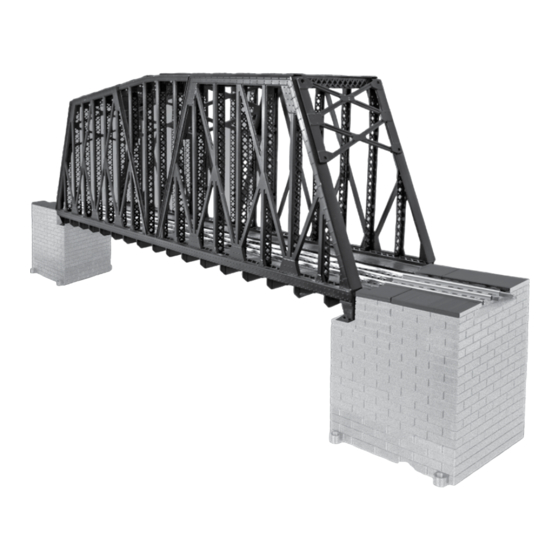
- Page 1 78-2110-250 7/23 Lionel FasTrack Lionel FasTrack Extended Truss Bridge Extended Truss Bridge Owner’s Manual Owner’s Manual...
- Page 2 Thank You! hank you for your purchase of the Lionel FasTrack Extended Truss Bridge! Perfect to use on any O Gauge layout, this versatile accessory allows you to use your bridge with FasTrack or tubular track as you create any kind of layout that you can imagine.
-
Page 3: Table Of Contents
Compatability with Tubular track elevated trestles Compatability with FasTrack elevated trestles Maximizing the overall height of the bridge Combining two or more bridges Incorporating the FasTrack girder bridge(s) 9-10 Positioning the bridge 11-14 Notes Lionel Limited Warranty Policy & Service... -
Page 4: Truss Bridge Basics
Truss Bridge Basics Unboxing your FasTrack Extended Truss Bridge nce you have the bridge removed from the polyfoam carefully slide the piers in the vac form out of the interior of the bridge. Once the piers have been removed you can install the upper front girder face of the bridge. -
Page 5: Bridge Pier Identification
Truss Bridge Basics Bridge pier identification he piers on this bridge have been engineered to accommodate several configurations. First, identify the pier sections for ease of reference: Pier Base (has mounting tabs) FasTrack Elevated Trestle Section (taller piece) Tubular track elevated trestle section Track mounting (top pier half ) (shorter piece) Bridge mounting (top pier half ) -
Page 6: Truss Bridge Assembly
Truss Bridge Assembly Compatibility with Tubular track elevated trestles o make the bridge compatible with Tubular O or O27 elevated trestles (available separately, 6-12755) stack the bridge piers as follows: 1. Track mounting top pier half (top) 2. Bridge mounting top pier half (top) 3. -
Page 7: Compatability With Fastrack Elevated Trestles
Truss Bridge Assembly Compatibility with FasTrack elevated trestles o make the bridge compatible with FasTrack elevated trestles (available separately, 6-12038) stack the bridge piers as follows: 1. Track mounting top pier half (top) 2. Bridge mounting top pier half (top) 3. -
Page 8: Maximizing The Overall Height Of The Bridge
Truss Bridge Assembly Maximizing the overall height of the bridge f you operate scale rolling stock and need the maximum amount of clearance under the bridge use both the FasTrack elevated trestle pier and the tubular track elevated trestle pier to achieve an overall height of 6.9”, enough space to clear Husky stack cars and auto carriers with ease. -
Page 9: Incorporating The Fastrack Girder Bridge(S)
Truss Bridge Assembly Incorporating the FasTrack girder bridge(s) ach track mating pier has been designed to allow you to incorporate a FasTrack Girder Bridge (available separately, 6-81248) as a lead into the FasTrack Extended Truss Bridge. If the girders are mounted to the top of the girder bridge base simply snap the girder bridge into the track mounting top pier half as shown below. - Page 10 Truss Bridge Assembly Incorporating the FasTrack girder bridge(s) continued Snap the FasTrack girder bridge with the inverted girders into the track mounting top pier half as shown in figure 11 below. Figure 11. Snap the girder bridge into place Snap the opposite end of the FasTrack Girder Bridge into another section of FasTrack mounted to an elevated trestle.
-
Page 11: Positioning The Bridge
Truss Bridge Assembly Positioning the bridge he FasTrack Extended Truss Bridge has been designed to be used as a lift out section for applications where there is a walkway underneath the bridge. To make the bridge a lift out simply position the piers on either side of the walkway opening and secure the piers with a 4 screws per pier, firmly mounting the piers in position. - Page 12 Truss Bridge Assembly Positioning the bridge continued If the bridge will not be used as a lift out section it can be securely fastened to the bridge piers using the 4 Phillips head screws included in the poly bag. The poly bag also includes six wire jumpers, used to create a wired connection between the piers and the rails on the bridge.
- Page 13 Truss Bridge Assembly Positioning the bridge continued Install screw Install screw Bridge pier top half Bridge Figure 15. Connecting the bridge pier to the bridge Carefully connect the red wire jumper to the center rail tab of the bridge. Also connect each black wire jumper to the outside rails of the bridge outside rail tabs.
- Page 14 Truss Bridge Assembly Positioning the bridge continued Snap the opposite top pier half (the track mounting top pier half or the bridge mounting top pier half if connecting two bridges together) into the bridge mounting top pier half. Flip the bridge over and position the bridge with piers attached to the pier stack.
-
Page 15: Notes
Notes... -
Page 16: Lionel Limited Warranty Policy & Service
Authorized Lionel Retailer*, will at the discretion of Lionel LLC, be repaired or replaced, without charge for parts or labor. In the event the defective product cannot be repaired, and a suitable replacement is not available, Lionel will offer to replace the product with a comparable model (determined by Lionel LLC), if available.
Need help?
Do you have a question about the FasTrack 78-2110-250 and is the answer not in the manual?
Questions and answers