Microchip Technology STK600 User Manual
Starter kit
Hide thumbs
Also See for STK600:
- User manual (114 pages) ,
- User manual (120 pages) ,
- User manual (35 pages)
Table of Contents
Advertisement
Quick Links
Overview
The STK600 is a complete starter kit and development system for the AVR
a quick start in developing code on the AVR device, combined with advanced features for using the starter kit to
prototype and test new designs.
New firmware releases for STK600 are embedded with the releases of Microchip Studio. The upgrade process starts
with a connection to the STK600 board (the user will be asked to perform the procedure). Should the automatic
upgrade fail, try the
©
2022 Microchip Technology Inc.
and its subsidiaries
Arrow.com.
Downloaded from
®
STK600 AVR
Flash MCU Starter Kit User's Guide
manual upgrade
procedure.
STK600 Starter Kit
®
Flash microcontroller. It allows designers
User Guide
DS40001904H-page 1
Advertisement
Table of Contents

Subscribe to Our Youtube Channel
Related Manuals for Microchip Technology STK600


Summary of Contents for Microchip Technology STK600
-
Page 1: Overview
New firmware releases for STK600 are embedded with the releases of Microchip Studio. The upgrade process starts with a connection to the STK600 board (the user will be asked to perform the procedure). Should the automatic upgrade fail, try the manual upgrade procedure. -
Page 2: Table Of Contents
Mounting the Cards........................43 5.5. Signal Integrity..........................49 ® 5.6. UC3 Routing Card Pin Mapping..................49 5.7. SAM Routing Cards........................77 Hardware Description..........................78 6.1. STK600 Block Diagram......................78 6.2. Target Voltage VTG........................78 6.3. Analog Reference Voltages......................79 6.4. RESET Control...........................81 6.5. Port Connectors......................... 82 6.6. - Page 3 STK600 Starter Kit Command-Line Utility.......................... 111 Troubleshooting and Support......................112 9.1. Troubleshooting Guide......................112 9.2. Routing and Socket Card Issues....................115 9.3. Technical Support........................115 9.4. Firmware Upgrade........................115 10. Revision History...........................117 The Microchip Website..........................118 Product Change Notification Service......................118 Customer Support............................118 Microchip Devices Code Protection Feature....................
-
Page 4: Features
STK600 Starter Kit Features Features ® • Microchip Studio/AVR Studio 5/AVR Studio 4/AVR32 Studio • USB Interface to PC for Programming and Control • Powered from the USB Bus or an External 10-15V DC Power Supply • Adjustable Target V (0-5.5V) -
Page 5: Known Issues
STK600 Starter Kit Known Issues Known Issues There are no known issues with the STK600. User Guide DS40001904H-page 5 © 2022 Microchip Technology Inc. and its subsidiaries Arrow.com. Downloaded from... -
Page 6: Device Support
STK600 Starter Kit Device Support Device Support ® Microchip Studio and MPLAB X have support for a range of devices in all speed grades. Support for new AVR devices may be added in new versions of the software. The latest versions of the Integrated Development Environments are always available from www.microchip.com. - Page 7 STK600 Starter Kit Device Support ...continued Device Routing Card Socket Card Comment AT32UC3B064 ATSTK600-RC21 - STK600- ATSTK600-SC21 - STK600-QFN64 RCUC3B0-21 AT32UC3B1128 ATSTK600-RC27 - STK600- ATSTK600-SC16 - STK600- RCUC3B48-27 TQFP48 AT32UC3B1128 ATSTK600-RC27 - STK600- ATSTK600-SC41 - STK600-QFN48 RCUC3B48-27 AT32UC3B1256 ATSTK600-RC27 - STK600-...
- Page 8 ATSTK600-RC09 - STK600-RC064M-9 ATSTK600-SC02 - STK600- TQFP64 AT90CAN64 ATSTK600-RC09 - STK600-RC064M-9 ATSTK600-SC21 - STK600-QFN64 AT90PWM1 ATSTK600-RC19 - STK600-RCPWM-19 ATSTK600-SC11 - STK600-SOIC AT90PWM161 ATSTK600-RC26 - STK600-RCPWM-26 ATSTK600-SC11 - STK600-SOIC AT90PWM216 ATSTK600-RC19 - STK600-RCPWM-19 ATSTK600-SC11 - STK600-SOIC AT90PWM2B ATSTK600-RC19 - STK600-RCPWM-19 ATSTK600-SC11 - STK600-SOIC...
- Page 9 STK600 Starter Kit Device Support ...continued Device Routing Card Socket Card Comment AT90PWM3 ATSTK600-RC19 - STK600-RCPWM-19 ATSTK600-SC11 - STK600-SOIC AT90PWM316 ATSTK600-RC19 - STK600-RCPWM-19 ATSTK600-SC11 - STK600-SOIC AT90PWM3B ATSTK600-RC19 - STK600-RCPWM-19 ATSTK600-SC11 - STK600-SOIC AT90PWM81 ATSTK600-RC26 - STK600-RCPWM-26 ATSTK600-SC11 - STK600-SOIC AT90USB1286...
- Page 10 STK600 Starter Kit Device Support ...continued Device Routing Card Socket Card Comment ATSAMC21E17A ATSTK600-RC89 - STK600- ATSTK600-SC12 - STK600-QFN32 Breakout board RC032SAM-89 only. STK600 cannot program this device ATSAMC21E18A ATSTK600-RC89 - STK600- ATSTK600-SC10 - STK600- Breakout board RC032SAM-89 TQFP32 only. STK600...
- Page 11 STK600 Starter Kit Device Support ...continued Device Routing Card Socket Card Comment ATSAMC21J15A ATSTK600-RC87 - STK600- ATSTK600-SC14 - STK600- Breakout board RC064SAM-87 TQFP64-2 only. STK600 cannot program this device ATSAMC21J15A ATSTK600-RC87 - STK600- ATSTK600-SC21 - STK600-QFN64 Breakout board RC064SAM-87 only. STK600...
- Page 12 STK600 Starter Kit Device Support ...continued Device Routing Card Socket Card Comment ATSAMC21J18A ATSTK600-RC87 - STK600- ATSTK600-SC21 - STK600-QFN64 Breakout board RC064SAM-87 only. STK600 cannot program this device ATSAMC21N17A ATSTK600-RC105 - STK600- ATSTK600-SC03 - STK600- Breakout board RC100SAM-105 TQFP100 only. STK600...
- Page 13 STK600 Starter Kit Device Support ...continued Device Routing Card Socket Card Comment ATSAMD20E15 ATSTK600-RC79 - STK600- ATSTK600-SC12 - STK600-QFN32 Breakout board RC032SAM-79 only. STK600 cannot program this device. ATSAMD20E15 ATSTK600-RC79 - STK600- ATSTK600-SC10 - STK600- Breakout board RC032SAM-79 TQFP32 only. STK600 cannot program this device.
- Page 14 STK600 Starter Kit Device Support ...continued Device Routing Card Socket Card Comment ATSAMD20E18 ATSTK600-RC79 - STK600- ATSTK600-SC10 - STK600- Breakout board RC032SAM-79 TQFP32 only. STK600 cannot program this device. ATSAMD20G14 ATSTK600-RC78 - STK600- ATSTK600-SC16 - STK600- Breakout board RC048SAM-78 TQFP48 only.
- Page 15 STK600 Starter Kit Device Support ...continued Device Routing Card Socket Card Comment ATSAMD20G16B ATSTK600-RC78 - STK600- ATSTK600-SC16 - STK600- Breakout board RC048SAM-78 TQFP48 only. STK600 cannot program this device. ATSAMD20G16B ATSTK600-RC78 - STK600- ATSTK600-SC41 - STK600-QFN48 Breakout board RC048SAM-78 only. STK600 cannot program this device.
- Page 16 STK600 Starter Kit Device Support ...continued Device Routing Card Socket Card Comment ATSAMD20J15 ATSTK600-RC72 - STK600- ATSTK600-SC21 - STK600-QFN64 Breakout board RC064SAM-72 only. STK600 cannot program this device. ATSAMD20J15B ATSTK600-RC72 - STK600- ATSTK600-SC14 - STK600- Breakout board RC064SAM-72 TQFP64-2 only. STK600 cannot program this device.
- Page 17 STK600 Starter Kit Device Support ...continued Device Routing Card Socket Card Comment ATSAMD21E15A ATSTK600-RC89 - STK600- ATSTK600-SC10 - STK600- Breakout board RC032SAM-89 TQFP32 only. STK600 cannot program this device. ATSAMD21E15A ATSTK600-RC89 - STK600- ATSTK600-SC12 - STK600-QFN32 Breakout board RC032SAM-89 only. STK600 cannot program this device.
- Page 18 STK600 Starter Kit Device Support ...continued Device Routing Card Socket Card Comment ATSAMD21E18A ATSTK600-RC89 - STK600- ATSTK600-SC12 - STK600-QFN32 Breakout board RC032SAM-89 only. STK600 cannot program this device. ATSAMD21G15A ATSTK600-RC88 - STK600- ATSTK600-SC16 - STK600- Breakout board RC048SAM-88 TQFP48 only. STK600 cannot program this device.
- Page 19 STK600 Starter Kit Device Support ...continued Device Routing Card Socket Card Comment ATSAMD21G18A ATSTK600-RC88 - STK600- ATSTK600-SC16 - STK600- Breakout board RC048SAM-88 TQFP48 only. STK600 cannot program this device. ATSAMD21G18A ATSTK600-RC88 - STK600- ATSTK600-SC41 - STK600-QFN48 Breakout board RC048SAM-88 only. STK600 cannot program this device.
- Page 20 STK600 Starter Kit Device Support ...continued Device Routing Card Socket Card Comment ATSAMD21J17A ATSTK600-RC87 - STK600- ATSTK600-SC21 - STK600-QFN64 Breakout board RC064SAM-87 only. STK600 cannot program this device. ATSAMD21J18A ATSTK600-RC87 - STK600- ATSTK600-SC14 - STK600- Breakout board RC064SAM-87 TQFP64-2 only. STK600 cannot program this device.
- Page 21 TQFP48 ATmega128 ATSTK600-RC09 - STK600-RC064M-9 ATSTK600-SC02 - STK600- TQFP64 ATmega128 ATSTK600-RC09 - STK600-RC064M-9 ATSTK600-SC21 - STK600-QFN64 ATmega1280 ATSTK600-RC11 - STK600-RC100M-11 ATSTK600-SC03 - STK600- TQFP100 ATmega1281 ATSTK600-RC09 - STK600-RC064M-9 ATSTK600-SC02 - STK600- TQFP64 ATmega1281 ATSTK600-RC09 - STK600-RC064M-9 ATSTK600-SC21 - STK600-QFN64 ATmega1284...
- Page 22 STK600 Starter Kit Device Support ...continued Device Routing Card Socket Card Comment ATmega162 ATSTK600-RC30 - STK600- ATSTK600-SC45 - STK600-QFN44 RC044M-30 ATmega164A ATSTK600-RC05 - STK600-RC040M-5 ATSTK600-SC01 - STK600-DIP ATmega164A ATSTK600-RC31 - STK600- ATSTK600-SC06 - STK600- RC044M-31 TQFP44 ATmega164A ATSTK600-RC31 - STK600-...
- Page 23 RC044M-24 TSSOP44 ATmega16HVBre ATSTK600-RC24 - STK600- ATSTK600-SC13 - STK600- RC044M-24 TSSOP44 ATmega16M1 ATSTK600-RC22 - STK600-RCPWM-22 ATSTK600-SC10 - STK600- TQFP32 ATmega16U2 ATSTK600-RC20 - STK600-RC032U-20 ATSTK600-SC12 - STK600-QFN32 ATmega16U2 ATSTK600-RC20 - STK600-RC032U-20 ATSTK600-SC10 - STK600- TQFP32 ATmega16U4 ATSTK600-RC25 - STK600-RC044U-25 ATSTK600-SC06 - STK600-...
- Page 24 STK600 Starter Kit Device Support ...continued Device Routing Card Socket Card Comment ATmega2560 ATSTK600-RC11 - STK600-RC100M-11 ATSTK600-SC03 - STK600- TQFP100 ATmega2561 ATSTK600-RC09 - STK600-RC064M-9 ATSTK600-SC02 - STK600- TQFP64 ATmega2561 ATSTK600-RC09 - STK600-RC064M-9 ATSTK600-SC21 - STK600-QFN64 ATmega32 ATSTK600-RC05 - STK600-RC040M-5 ATSTK600-SC01 - STK600-DIP...
- Page 25 STK600 Starter Kit Device Support ...continued Device Routing Card Socket Card Comment ATmega3250PA ATSTK600-RC18 - STK600- ATSTK600-SC03 - STK600- RC100M-18 TQFP100 ATmega325A ATSTK600-RC10 - STK600- ATSTK600-SC02 - STK600- RC064M-10 TQFP64 ATmega325A ATSTK600-RC10 - STK600- ATSTK600-SC21 - STK600-QFN64 RC064M-10 ATmega325P ATSTK600-RC10 - STK600-...
- Page 26 ATSTK600-RC31 - STK600- ATSTK600-SC06 - STK600- RC044M-31 TQFP44 ATmega32A ATSTK600-RC31 - STK600- ATSTK600-SC45 - STK600-QFN44 RC044M-31 ATmega32C1 ATSTK600-RC22 - STK600-RCPWM-22 ATSTK600-SC10 - STK600- TQFP32 ATmega32HVB ATSTK600-RC24 - STK600- ATSTK600-SC13 - STK600- RC044M-24 TSSOP44 ATmega32HVBre ATSTK600-RC24 - STK600- ATSTK600-SC13 - STK600-...
- Page 27 RC032M-91 ATmega64 ATSTK600-RC09 - STK600-RC064M-9 ATSTK600-SC02 - STK600- TQFP64 ATmega64 ATSTK600-RC09 - STK600-RC064M-9 ATSTK600-SC21 - STK600-QFN64 ATmega640 ATSTK600-RC11 - STK600-RC100M-11 ATSTK600-SC03 - STK600- TQFP100 ATmega644 ATSTK600-RC05 - STK600-RC040M-5 ATSTK600-SC01 - STK600-DIP ATmega644 ATSTK600-RC31 - STK600- ATSTK600-SC06 - STK600- RC044M-31 TQFP44...
- Page 28 ATmega64A ATSTK600-RC09 - STK600-RC064M-9 ATSTK600-SC02 - STK600- TQFP64 ATmega64A ATSTK600-RC09 - STK600-RC064M-9 ATSTK600-SC21 - STK600-QFN64 ATmega64C1 ATSTK600-RC22 - STK600-RCPWM-22 ATSTK600-SC10 - STK600- TQFP32 ATmega64M1 ATSTK600-RC22 - STK600-RCPWM-22 ATSTK600-SC10 - STK600- TQFP32 User Guide DS40001904H-page 28 © 2022 Microchip Technology Inc.
- Page 29 STK600 Starter Kit Device Support ...continued Device Routing Card Socket Card Comment ATmega8 ATSTK600-RC29 - STK600- ATSTK600-SC10 - STK600- RC032M-29 TQFP32 ATmega8 ATSTK600-RC29 - STK600- ATSTK600-SC12 - STK600-QFN32 RC032M-29 ATmega8 ATSTK600-RC06 - STK600-RC028M-6 ATSTK600-SC01 - STK600-DIP ATmega809 ATSTK600-RC107 - STK600-...
- Page 30 TQFP32 ATmega8A ATSTK600-RC29 - STK600- ATSTK600-SC12 - STK600-QFN32 RC032M-29 ATmega8A ATSTK600-RC06 - STK600-RC028M-6 ATSTK600-SC01 - STK600-DIP ATmega8U2 ATSTK600-RC20 - STK600-RC032U-20 ATSTK600-SC12 - STK600-QFN32 ATmega8U2 ATSTK600-RC20 - STK600-RC032U-20 ATSTK600-SC10 - STK600- TQFP32 ATtiny10 ATSTK600-ATTINY10 - STK600- ATTINY10 ATtiny102 ATSTK600-RC102 - STK600-...
- Page 31 ATSTK600-RC01 - STK600-RC020T-1 ATSTK600-SC01 - STK600-DIP ATtiny2313A ATSTK600-RC01 - STK600-RC020T-1 ATSTK600-SC01 - STK600-DIP ATtiny24 ATSTK600-RC12 - STK600-RC014T-12 ATSTK600-SC01 - STK600-DIP ATtiny24 ATSTK600-RC46 - STK600-RC014T-46 ATSTK600-SC11 - STK600-SOIC ATtiny24A ATSTK600-RC12 - STK600-RC014T-12 ATSTK600-SC01 - STK600-DIP ATtiny24A ATSTK600-RC46 - STK600-RC014T-46 ATSTK600-SC11 - STK600-SOIC...
- Page 32 ATtiny4313 ATSTK600-RC01 - STK600-RC020T-1 ATSTK600-SC01 - STK600-DIP ATtiny43U ATSTK600-Tinyx3U - STK600- TINYX3U ATtiny44 ATSTK600-RC12 - STK600-RC014T-12 ATSTK600-SC01 - STK600-DIP ATtiny44 ATSTK600-RC46 - STK600-RC014T-46 ATSTK600-SC11 - STK600-SOIC ATtiny441 ATSTK600-RC46 - STK600-RC014T-46 ATSTK600-SC11 - STK600-SOIC ATtiny44A ATSTK600-RC12 - STK600-RC014T-12 ATSTK600-SC01 - STK600-DIP...
- Page 33 ATSTK600-SC11 - STK600-SOIC RC020T-104 ATtiny827 ATSTK600-RC103 - STK600- ATSTK600-SC62 - STK600-QFN24 RC024T-103 ATtiny828 ATSTK600-RC56 - STK600-RC032T-56 ATSTK600-SC10 - STK600- TQFP32 ATtiny828 ATSTK600-RC56 - STK600-RC032T-56 ATSTK600-SC12 - STK600-QFN32 ATtiny84 ATSTK600-RC12 - STK600-RC014T-12 ATSTK600-SC01 - STK600-DIP ATtiny84 ATSTK600-RC46 - STK600-RC014T-46 ATSTK600-SC11 - STK600-SOIC...
- Page 34 STK600 Starter Kit Device Support ...continued Device Routing Card Socket Card Comment ATxmega128A1 ATSTK600-RC13 - STK600-RC100X-13 ATSTK600-SC03 - STK600- TQFP100 ATxmega128A1U ATSTK600-RC13 - STK600-RC100X-13 ATSTK600-SC03 - STK600- since rev.10 TQFP100 (A09-0117/10) ATxmega128A1U ATSTK600-RC13 - STK600-RC100X-13 ATSTK600-SC03 - STK600- since rev.10 TQFP100 (A09-0117.10)
- Page 35 STK600 Starter Kit Device Support ...continued Device Routing Card Socket Card Comment ATxmega16A4U ATSTK600-RC55 - STK600-RC044X-55 ATSTK600-SC45 - STK600-QFN44 ATxmega16C4 ATSTK600-RC55 - STK600-RC044X-55 ATSTK600-SC06 - STK600- TQFP44 ATxmega16C4 ATSTK600-RC55 - STK600-RC044X-55 ATSTK600-SC45 - STK600-QFN44 ATxmega16D4 ATSTK600-RC15 - STK600-RC044X-15 ATSTK600-SC06 - STK600-...
- Page 36 STK600 Starter Kit Device Support ...continued Device Routing Card Socket Card Comment ATxmega256A3B ATSTK600-RC51 - STK600-RC064X-51 ATSTK600-SC21 - STK600-QFN64 ATxmega256A3U ATSTK600-RC51 - STK600-RC064X-51 ATSTK600-SC02 - STK600- TQFP64 ATxmega256A3U ATSTK600-RC51 - STK600-RC064X-51 ATSTK600-SC21 - STK600-QFN64 ATxmega256C3 ATSTK600-RC51 - STK600-RC064X-51 ATSTK600-SC02 - STK600-...
- Page 37 STK600 Starter Kit Device Support ...continued Device Routing Card Socket Card Comment ATxmega384D3 ATSTK600-RC51 - STK600-RC064X-51 ATSTK600-SC02 - STK600- TQFP64 ATxmega384D3 ATSTK600-RC14 - STK600-RC064X-14 ATSTK600-SC21 - STK600-QFN64 ATxmega384D3 ATSTK600-RC51 - STK600-RC064X-51 ATSTK600-SC21 - STK600-QFN64 ATxmega64A1 ATSTK600-RC13 - STK600-RC100X-13 ATSTK600-SC03 - STK600-...
- Page 38 STK600 Starter Kit Device Support ...continued Device Routing Card Socket Card Comment ATxmega8E5 ATSTK600-RC64 - STK600-RC032X-64 ATSTK600-SC10 - STK600- TQFP32 ATxmega8E5 ATSTK600-RC64 - STK600-RC032X-64 ATSTK600-SC12 - STK600-QFN32 AVR128DA48 ATSTK600-RC107 - STK600- ATSTK600-SC16 - STK600- Breakout board RC048M-107 TQFP48 only. STK600 cannot program this device.
-
Page 39: Getting Started
The power switch turns the STK600 main power ON and OFF. The red LED is lit when the power is ON, and the status LED will turn green. The green LED beside the VTG jumper indicates that the target voltage is present. -
Page 40: Connecting The Hardware
Connecting the Hardware The STK600 must be connected to a host PC with a USB cable. Connect the cable to a free USB port on the PC or a USB hub. The USB port must be capable of supplying 500 mA. If using a USB hub, make sure it has an external power supply. -
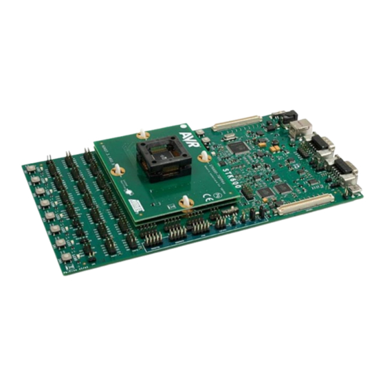
Page 41: Target Socket System
Target Socket System Socket System STK600 is designed to support all AVR devices with internal Flash memory. A system based on socket and routing cards is used to support different package types and pinouts on the STK600 board. The picture below shows an STK600 with a mounted routing card and socket card. - Page 42 STK600 Starter Kit Target Socket System A routing card is a device-specific card. It routes signals between the STK600 motherboard and the socket card. Note that several devices may use the same routing card if they share the same pinout.
-
Page 43: Selecting The Correct Routing And Socket Cards
Mounting the routing and socket cards can either be done by plastic clips or plastic screws/nuts. Both sets are included in the STK600 package. Install either the clips or the nuts to the motherboard, depending on what solution you want to use. - Page 44 STK600 Starter Kit Target Socket System 5.4.1.2 Routing Card Align the clips with the white lines on the motherboard. The routing card can now be placed above the four clips. Make sure that the routing card has the correct orientation (i.e., the text should face upwards, and the white dot in...
- Page 45 STK600). Press down the routing card (i.e., compress the spring-loaded connector on the STK600) and turn the clip 45 degrees in the clockwise direction so that it aligns with the white line on the routing card.
- Page 46 STK600 Starter Kit Target Socket System 5.4.1.3 Socket Card Connecting the socket card is done in the same way as the routing card. Make sure that the clips align with the white line outside the clip holes on the routing card, then mount the socket card. The white spot on the socket card should...
- Page 47 STK600 Starter Kit Target Socket System align with the one on the routing card. Press down the socket card (i.e., compress the spring-loaded connector on the socket card) and turn the clip 45 degrees in the clockwise direction until it aligns with the white line outside the clip hole.
- Page 48 5.4.2 Using Screws and Nuts 5.4.2.1 Motherboard Insert the nuts into the STK600 motherboard from the bottom side. When properly installed, the two locking springs should hold the nut in place. 5.4.2.2 Routing and Socket Card Place the routing card above the motherboard and make sure that the white spot in the corner matches the white spot on the motherboard.
-
Page 49: Signal Integrity
Due to this, the signal integrity is not optimized. STK600 is not a reference design in any way but a kit that serves as a socket programmer with some additional peripheral hardware to get started with the AVR device. - Page 50 STK600 Starter Kit Target Socket System ...continued Device Pin Name STK600 Pin Name PB10 PB11 RESET RESET AREF0 AREF0 VBUS VBUST VDDANA VDDCORE VDDIN VDDOUT VDDPLL STK600-RCUC3B48-27 Device Pin Name STK600 Pin Name PA10 PA11 PB3, TOSC1 PA12 TOSC2, PB4...
- Page 51 STK600 Starter Kit Target Socket System ...continued Device Pin Name STK600 Pin Name PA13 PA14 PB6, MOSI PA15 PB7, SCK PA16 PA17 PA18 XTAL1, PC2 PA19 PC3, XTAL2 PA20 PA21 PA22 PA23 PA24 PA25 PD1, MISO PA26 PA27 RESET RESET...
- Page 52 STK600 Starter Kit Target Socket System ...continued Device Pin Name STK600 Pin Name VDDPLL STK600-RCUC3A100-28 Device Pin Name STK600 Pin Name PA00 PA01 PA02 PA03 PA04 PA05 PA06 PA07 PA08 PA09 PA10 PA11 PB3, MISO PA12 PB4, MOSI PA13 PB5, SCK...
- Page 53 STK600 Starter Kit Target Socket System ...continued Device Pin Name STK600 Pin Name PA31 PB00 PB01 PB02 PB03 PB04 PB05 PB06 PB07 PB08 PB09 PB10 PB11 PB12 PB13 PB14 PB15 PB16 PB17 PB18 PB19 PB20 PB21 PB22 PB23 PB24 PB25...
- Page 54 STK600 Starter Kit Target Socket System ...continued Device Pin Name STK600 Pin Name PC02 XTAL1 PC03 XTAL2 PC04 PC05 AREF0 AREF0 RESET RESET VBUS VBUST VDDANA VDDCORE VDDIN VDDPLL STK600-RCUC3A144-32 Device Pin Name STK600 Pin Name PA00 PA01 PA02 PA03...
- Page 55 STK600 Starter Kit Target Socket System ...continued Device Pin Name STK600 Pin Name PA14 PA15 PA16 PA17 PA18 PA19 PA20 PA21 PA22 PA23 PA24 PA25 PA26 PA27 PA28 PA29 PA30 PA31 PB00 PB01 PB02 PB03 PB04 PB05 PB06 PB07 PB08...
- Page 56 STK600 Starter Kit Target Socket System ...continued Device Pin Name STK600 Pin Name PC05 PX00 PX01 PX02 PX03 PX04 PX05 PX06 PX07 PX08 PX09 PX10 PX11 PX12 PX13 PX14 PX15 PX16 PX17 PX18 PX19 PX20 PX21 PX22 PX23 PX24 PX25...
- Page 57 STK600 Starter Kit Target Socket System ...continued Device Pin Name STK600 Pin Name PX34 PX35 PX36 PX37 PX38 PX39 PX40 PX41 PX42 PX43 PX44 PX45 PX46 PX47 PX48 PX49 PX50 PX51 PX52 PX53 PX54 PX55 PX56 PX57 PX58 PX59 RESET_N...
- Page 58 STK600 Starter Kit Target Socket System ...continued Device Pin Name STK600 Pin Name FSDP VDDANA VDDCORE VDDIN STK600-RCUC3A144-33 Device Pin Name STK600 Pin Name PA00 PA01 PA02 PA03 PA04 PA05 PA06 PA07 PA08 PA09 PA10 PA11 PB3, MISO PA12 PB4, MOSI...
- Page 59 STK600 Starter Kit Target Socket System ...continued Device Pin Name STK600 Pin Name PA27 PD3, PL5 PA28 PD4, PL6 PA29 PA30 PB00 PB01 PB02 PB03 PB04 PE4, PP3 PB05 PB06 PB07 PB08 PB09 PB10 PB11 PB12 PB13 PB14 PB15 PB16...
- Page 60 STK600 Starter Kit Target Socket System ...continued Device Pin Name STK600 Pin Name PB31 PH7, PP6 PC00 TOSC1 PC01 TOSC2 PC02 XTAL1 PC03 XTAL2 PC04 PC05 PX00 PX01 PX02 PX03 PX04 PX05 PX06 PX07 PX08 PX09 PX10 PX11 PX12 PX13...
- Page 61 STK600 Starter Kit Target Socket System ...continued Device Pin Name STK600 Pin Name PX28 PX29 PX30 PX31 PX32 PX33 PX34 PX35 PX36 PX37 PX38 PX39 RESET_N RESET VBUS VBUST ADVREF AREF0 VDDANA VDDCORE VDDIN STK600-RCUC3L0-34 Device Pin Name STK600 Pin Name...
- Page 62 STK600 Starter Kit Target Socket System ...continued Device Pin Name STK600 Pin Name PA07 PA08 PB0, XTAL1 PA09 PB1, XTAL2 PA10 PB2, PH1 PA11 PA12 PA13 PB5, PH3 PA14 PA15 PA16 PA17 PA18 PA19 PA20 PA21 PA22 PB00 PB01 PB02...
- Page 63 STK600 Starter Kit Target Socket System ...continued Device Pin Name STK600 Pin Name GNDANA STK600-RCUC3C0-36 Device Pin Name STK600 Pin Name PA00 PA0, TCK PA01 PA1, TDI PA02 PA2, TDO PA03 PA3, TMS PA04 PA05 PA06 PA07 PA08 PA09 PA10...
- Page 64 STK600 Starter Kit Target Socket System ...continued Device Pin Name STK600 Pin Name PA29 PB00 PE0, TOSC1 PB01 PE1, TOSC2 PB02 PB03 PB04 PB05 PB06 PB07 PB08 PB09 PB10 PB11 PB12 PB13 PB14 PB15 PB16 PB17 PB18 PB19 PB20 PB21...
- Page 65 STK600 Starter Kit Target Socket System ...continued Device Pin Name STK600 Pin Name PC02 PC03 PC04 PC05 PC06 PC07 PC08 PC09 PC10 PC11 PC12 PC13 PC14 PC15 PC16 PC17 PC18 PC19 PC20 PC21 PC22 PC23 PC24 PC25 PC26 PC27 PC28...
- Page 66 STK600 Starter Kit Target Socket System ...continued Device Pin Name STK600 Pin Name PD05 PD06 PD07 PD08 PD09 PD10 PD11 PD12 PD13 PD14 PD15 PD16 PD17 PD18 PD19 PD20 PD21 PD22 PD23 PD24 PDATA0 PD25 PDATA1 PD26 PDATA2 PD27 PDATA3...
- Page 67 STK600 Starter Kit Target Socket System Device Pin Name STK600 Pin Name PA00 PA0, TCK PA01 PA1, TDI PA02 PA2, TDO PA03 PA3, TMS PA04 PA05 PA06 PA07 PA08 PA09 PA10 PA11 PB3, AREF1 PA12 PA13 PA14 PA15 PA16 PC0, AREF0...
- Page 68 STK600 Starter Kit Target Socket System ...continued Device Pin Name STK600 Pin Name PB22 PB23 PB30 PH6, XTAL1 PB31 PH7, XTAL2 PC00 PC01 PJ1, UVCON PC02 PC03 PC04 PC05 PC06 PC07 PC11 PC12 PC13 PC14 PC15 PC16 PC17 PC18 PC19...
- Page 69 STK600 Starter Kit Target Socket System ...continued Device Pin Name STK600 Pin Name PD11 PD12 PD13 PD14 PD21 PD22 PD23 PD24 PDATA0 PD27 PDATA3 PD28 PDATA4 PD29 PDATA5 PD30 PDATA6 RESET MISO, RESET VBUS VBUST VDDANA VDDCORE VDDIN STK600-RCUC3C2-40 Device Pin Name...
- Page 70 STK600 Starter Kit Target Socket System ...continued Device Pin Name STK600 Pin Name PA18 PA19 PA20 PA21 PA22 PA23 PB00 PE0, TOSC1 PB01 PE1, TOSC2 PB30 PH6, XTAL1 PB31 PH7, XTAL2 PC02 PC03 PC04 PC05 PC15 PC16 PC17 PC18 PC19...
- Page 71 STK600 Starter Kit Target Socket System ...continued Device Pin Name STK600 Pin Name RESET MISO, RESET VBUS VBUST VDDANA VDDCORE VDDIN STK600-RCUC3L3U-47 Device Pin Name STK600 Pin Name PA00 TCK, PA0 PA01 PA1, TMS PA02 PA2, TDO PA03 PA3, TDI...
- Page 72 STK600 Starter Kit Target Socket System ...continued Device Pin Name STK600 Pin Name PB01 PB02 PB03 PB04 PB05 PB06 PB07 PB08 PB09 PB10 PB11 PB12 PB13 PE5, DN PB14 PE6, DP PB15 PB16 PB17 PB18 PB19 PB20 PB21 PB22 PB23...
- Page 73 STK600 Starter Kit Target Socket System Device Pin Name STK600 Pin Name PA0, TDI PA10 PA11 PB3, TOSC1 PA12 PB4, TOSC2 PA13 PA14 PA15 PA16 PA17 PA18 PC2, XTAL1 PA19 PC3, XTAL2 PA1, TDO PA20 PA21 PA22 PA23 PA24 PA25...
- Page 74 STK600 Starter Kit Target Socket System ...continued Device Pin Name STK600 Pin Name PB13 PB14 PB15 PB16 PG0, VBUST PB17 PB18 RESET MISO, RESET AREF0 AREF0 VDDANA VDDCORE VDDIN VDDOUT STK600-RCUC3D4-49 Device Pin Name STK600 Pin Name PA00 PA0, TDI...
- Page 75 STK600 Starter Kit Target Socket System ...continued Device Pin Name STK600 Pin Name PA08 PA09 PA10 PA11 PB3, TOSC1 PA12 PB4, TOSC2 PA13 PA14 PA15 PA16 PA17 PA18 PC2, XTAL1 PA19 PC3, XTAL2 PA20 PA21 PA22 PA23 PA24 PA25 PA26...
- Page 76 STK600 Starter Kit Target Socket System ...continued Device Pin Name STK600 Pin Name STK600-RCUC3L4U-53 Device Pin Name STK600 Pin Name PA00 PA0, TCK PA01 PA1, TMS PA02 PA2, TDO PA03 PA3, TDI PA04 PA05 PA06 PA6, VBUST PA08 PB0, XTAL1...
-
Page 77: Sam Routing Cards
VDDIO SAM Routing Cards A special RC064SAM-72 routing card has been made to allow SAM D20J devices to connect to STK600. This breaks out the pins to the pins on the STK600. Note: The STK600 itself cannot communicate with the SAM device as the STK600 does not support SWD or the JTAG commands needed for SAM devices. -
Page 78: Hardware Description
Target Voltage VTG The VTG voltage is the supply voltage to the target AVR microcontroller. It is connected to the AVR device VCC pin. VTG can either be generated by STK600 or be supplied from an external source. User Guide DS40001904H-page 78 ©... -
Page 79: Analog Reference Voltages
If a short circuit is detected when using the on-board VTG supply, the STK600 status LED will blink red. Analog Reference Voltages The A/D converter of the AVR device needs a reference voltage to set its converting range. STK600 can supply two of these voltages; AREF0 and AREF1. - Page 80 VTG value from the programming dialog in Microchip Studio before setting AREF. Note: The AREF0 and AREF1 voltages, which are visible in the PC software, are the STK600 generated voltages. Externally applied AREF voltages cannot be read from Microchip Studio.
-
Page 81: Reset Control
STK600 during programming. 6.4.2 The RESET Button STK600 has a reset button that resets the target AVR device when being pushed. The button has no function if the RESET jumper is not mounted. 6.4.3 RESET Signal on AUX Header The target RESET signal of the AVR device is accessible on the AUX header. -
Page 82: Port Connectors
When connected to an external system, there is often an external pull-up resistor and a capacitor connected to the reset line. A typical reset connection is shown below. If the external pull-up resistor is too strong (i.e., << 4.7 kΩ), STK600 may not be able to pull the RESET line low. See also section 7.9.1. -
Page 83: Leds And Switches
The TOSC1 pin can easily be connected to the AUX portʼs 32 KHz pin (32.768 kHz clock signal) by a jumper. LEDs and Switches STK600 has eight LEDs and eight switches that can be connected to I/O pins on the AVR device. The LEDS and SWITCHES connectors are found in the port connector area. 6.6.1 LEDs The LEDs are labeled LED0 to LED7. -
Page 84: Clock Settings
Note: On most AVR device pins configured as input, you can enable an internal pull-up, removing the need for an external pull-up on the push button. In the STK600 design, an external 10 kΩ pull-up is present to give all users a logical ̔... - Page 85 STK600 Starter Kit Hardware Description A switch selects between the following three options: • Programmable clock generator • Crystal oscillator (with a socket for a crystal) • XTAL1 Pin tri-stated (to be used with the AVR deviceʼs internal RC oscillator) 6.7.1...
-
Page 86: User Rs-232 Interface
Some AVR devices have an XTAL1 pin, which can also be used as a regular I/O port pin. The routing card for these devices will connect the device pin to both the XTAL1 net and a port pin header on the STK600. Hence, to use the pin as an I/O port, the clock selection switch must be set to position INT to disconnect the clock drivers on STK600 from the pin. -
Page 87: Dataflash Nonvolatile Memory
DataFlash Nonvolatile Memory An AT45DB041B 4 Mb DataFlash is included on the STK600 for nonvolatile data storage. This is a high-density Flash memory chip with Serial Peripheral Interface (SPI). A detailed data sheet of the DataFlash can be obtained from the Microchip website. -
Page 88: Expansion Connectors
DATAFLASH can be used for connecting the SPI of the DataFlash to the I/O pins on the target AVR microcontroller in the socket. Two-wire cables are included with STK600 for connecting the DataFlash to the I/O pins. The connection of the I/O pins is shown in the figure below. - Page 89 STK600 Starter Kit Hardware Description The connectors to be used on an expansion board are manufactured by FCI and have P/N: 61082-101402LF. See also www.fciconnect.com for more information. The connectors must be placed with exactly 119 mm from center to center. The expansion board must have a maximum width of 55 mm to avoid collision with components on the mainboard.
- Page 90 STK600 Starter Kit Hardware Description ...continued EXPAND0 EXPAND1 VEXT VEXT PDATA0 PDATA1 PDATA2 PDATA3 XTAL1 AREF0 PDATA4 PDATA5 XTAL2 AREF1 PDATA6 PDATA7 MOSI PCTRL0 PCTRL1 TOSC1 MISO PCTRL2 PCTRL3 TOSC2 PCTRL4 PCTRL5 TGT_RST PCTRL6 PCTRL7 VCC6 VCC3 B_ID0 B_ID1 User Guide DS40001904H-page 90 ©...
-
Page 91: User Usb Connector
6.11 User USB Connector STK600 has a USB connector that the target AVR devices with a USB interface can utilize. The connector is a Mini-AB connector that supports on-the-go functionality. The routing card for the device connects the USB connector to the appropriate pins on the AVR device. -
Page 92: Can Transceiver
Controller Area Network (CAN) is a broadcast, differential serial bus standard typically used in the automotive industry. The CAN features high immunity to electromechanical noise and arbitration-free fixed priority. STK600 features the ATA6660 CAN transceiver. A male DB9 connector and a 10-pin header are provided for a bus connection. - Page 93 The CAN transceiver is connected to the MCU through the two-pin (RX and TX) ̔ C ANʼ header near the switches on STK600. The target MCU can be any AVR device (bit-banging or USART), but more typically, it is one of the AT90CAN series, which supports the CAN protocol in hardware.
-
Page 94: Lin Transceiver
For further reference, see the ATA6661 data sheet. The LIN transceiver is connected to the MCU through the 6-pin ̔ L INʼ header near the switches on STK600. The target MCU will usually implement the LIN protocol in software through a USART interface. The ̔ N SLPʼ pin must be actively driven high to keep the ATA6661 from a sleep mode. -
Page 95: Miscellaneous
6.14.2 Main Power LED The red power LED is directly connected to the STK600 main power supply. The power LED is always lit when power is applied to STK600. 6.14.3 Target Power LED The target power LED is lit when the voltage applied to the target AVR device is 0.9V or higher. -
Page 96: Programming
Flash and EEPROM, fuses, lock-bits, and calibration bytes. Note: The ISP frequency (SCK) must be less than 1/4 of the target clock. The ISP frequency is set by the STK600 programming dialog in Microchip Studio. -
Page 97: Parallel High-Voltage Programming
Mount the routing and socket card and the target device. See the Socket System section on how to do this. Use the two 10-wire cables supplied with the STK600 to connect the PROG DATA and the PROG CTRL to the target device, as shown in the picture below. -
Page 98: Serial High-Voltage Programming
Programming Ensure that VTarget is between 4.5V and 5.5V. See the Programming Dialog pages in the Microchip Studio help file for information on the STK600 programming dialog. Note: The AREF jumper must be removed before programming of devices that have AREF on a pin used by the high-voltage programming interface. - Page 99 Mount the routing and socket card and the target device. See the Socket System section on how to do this. Use a 10-wire cable supplied with the STK600 to connect the PROG DATA to the target device, as shown in the picture below.
-
Page 100: Jtag Programming
Mount the routing and socket card and the target device. See the Socket System section on how to do this. Connect a 10-wire cable between the two 10-pin JTAG headers on the STK600. See the picture below. Ensure that the VTARGET jumper is mounted and that the voltage is within the operating range for the target device. -
Page 101: Pdi Programming
STK600 Starter Kit Programming See the Programming Dialog pages in the Microchip Studio help file or the AVR32 Studio help for information on how to program the device using JTAG. The pinout of the JTAG header is shown below: See also section 7.9. - Page 102 STK600 Starter Kit Programming The PDI interface requires two of the deviceʼs pins; PDI_DATA and PDI_CLOCK. On STK600, they are found on the ISP/PDI connector. 7.5.1 Hardware Setup for On-Board Programming Mount the routing and socket card and the target device. See the Socket System section on how to do this.
-
Page 103: Updi Programming
It can, in-system, download code into the Flash application and boot memories, EEPROM memory, fuses, lock-bits, and signature information. The UPDI interface requires one of the deviceʼs pins; UPDI_DATA. On STK600, it is found on the ISP/PDI connector. 7.6.1 Hardware Setup for On-Board Programming Mount the routing and socket card and the target device. -
Page 104: Awire Programming
STK600 Starter Kit Programming The pinout of the 6-pin ISP/PDI header when in UPDI mode is shown below: aWire Programming Some AVR UC3 devices have the aWire programming and debugging interface. It can, in-system, download code into the memories. User Guide DS40001904H-page 104 ©... - Page 105 STK600 Starter Kit Programming The aWire interface requires only the reset pins for serial communication. On STK600, it is found on the ISP/PDI or the JTAG connector. 7.7.1 Hardware Setup for aWire Programming Connect aWire using a 6-pin cable between the ISP/PDI connectors.
-
Page 106: Tpi Programming
STK600 Starter Kit Programming The pinout of the 10-pin JTAG header is shown below: TPI Programming The TPI (Tiny Programming Interface) found on some tinyAVR devices can download code into the memories of these devices. User Guide DS40001904H-page 106 ©... - Page 107 STK600 Starter Kit Programming The TPI interface requires two of the deviceʼs pins, TPIDATA and TPICLK, in addition to the RESET pin. On STK600, they are found on the ISP/PDI connector. Note: TPI should only be used on-board. It is not safe to program a device on an external board through the TPI interface.
-
Page 108: In-System Programming Of An External Target System
The STK600 can be used as a programmer to program AVR devices in other applications. There are two different ISP connector pinouts available; a 6-pin and a 10-pin version. Both are supported by STK600. The 6-pin header is a combined ISP and PDI connector. Also, STK600 can be used as a JTAG programmer for AVR devices with a JTAG interface. - Page 109 STK600 Starter Kit Programming Select the device to be programmed in the same way as programming a device on STK600. The VCC of the target application is detected by STK600, and signals are converted into voltage levels suitable for the target system.
- Page 110 Reset Line The reset line on any target board connected to STK600 should have a pull-up resistor. This pull-up should not be stronger than 2.2 kΩ (i.e., it should not be below 2.2 kΩ). If the pull-up resistor on the reset line is too strong, the short circuit protection will trigger when the reset is forced low by the STK600.
-
Page 111: Command-Line Utility
Microchip Studio comes with a command-line utility called atprogram that can be used to program targets using the STK600. During the Microchip Studio installation, a shortcut called “Microchip Studio 7.0 Command Prompt” was created in the Atmel folder on the Start menu. By double-clicking this shortcut, a command prompt will be opened, and programming commands can be entered. -
Page 112: Troubleshooting And Support
• Connect a USB cable between STK600 and a PC. Make sure the PC is turned on. • Connect a DC power cable to STK600. Note: The DC jack must have a center pin with positive polarity. The pre-programmed example... - Page 113 Reset disable fuse is set Check the reset disable fuse SPI frequency is too high Check STK600 SPI frequency and make sure it is lower than the target clock divided by 4 CKDIV fuse is set Reduce ISP programming speed External pull-up resistor on the Ensure that the external pull-up resistor is ≥4.7...
- Page 114 Slave MCU not responding Force STK600 into Bootloader mode, and perform a firmware upgrade The LEDs do not work (running STK600 must be powered for Supply power to STK600 and turn it ON from external VTarget) LEDs to work User Guide DS40001904H-page 114 ©...
-
Page 115: Routing And Socket Card Issues
For information on how to upgrade the firmware, see the Microchip Studio user guide. 9.4.1 Manual Firmware Upgrade If an automatic firmware upgrade fails or, for some other reason, a connection to STK600 cannot be established, a manual firmware upgrade may solve the problem. User Guide DS40001904H-page 115 ©... - Page 116 Before starting this procedure, make sure the latest Microchip Studio release is installed on the computer. Turn off STK600 and connect it to the PC using the USB cable. Press and hold the PROGRAM button when turning ON the STK600 power switch. The status LED will flash red and orange, indicating upgrade mode.
-
Page 117: Revision History
STK600 Starter Kit Revision History Revision History Doc Rev. Date Comments 02/2021 Updated Device Support 12/2020 Updated Device Support 09/2020 Updated Device Support 09/2019 • Updated Device Support • Several editorial updates 05/2018 Updated 6.12 and 6.13 due to new part numbers for LIN and CAN transceivers. Updated Device Support section with product names in addition to order code. -
Page 118: The Microchip Website
STK600 Starter Kit The Microchip Website Microchip provides online support via our website at www.microchip.com/. This website is used to make files and information easily available to customers. Some of the content available includes: • Product Support – Data sheets and errata, application notes and sample programs, design resources, user’s guides and hardware support documents, latest software releases and archived software •... -
Page 119: Trademarks
The Adaptec logo, Frequency on Demand, Silicon Storage Technology, Symmcom, and Trusted Time are registered trademarks of Microchip Technology Inc. in other countries. GestIC is a registered trademark of Microchip Technology Germany II GmbH & Co. KG, a subsidiary of Microchip Technology Inc., in other countries. -
Page 120: Quality Management System
STK600 Starter Kit Quality Management System For information regarding Microchip’s Quality Management Systems, please visit www.microchip.com/quality. User Guide DS40001904H-page 120 © 2022 Microchip Technology Inc. and its subsidiaries Arrow.com. Downloaded from... -
Page 121: Worldwide Sales And Service
Sweden - Stockholm San Jose, CA Tel: 46-8-5090-4654 Tel: 408-735-9110 UK - Wokingham Tel: 408-436-4270 Tel: 44-118-921-5800 Canada - Toronto Fax: 44-118-921-5820 Tel: 905-695-1980 Fax: 905-695-2078 User Guide DS40001904H-page 121 © 2022 Microchip Technology Inc. and its subsidiaries Arrow.com. Downloaded from...
Need help?
Do you have a question about the STK600 and is the answer not in the manual?
Questions and answers