Table of Contents
Advertisement
Quick Links
PIC16F18076 Curiosity Nano Hardware User Guide
Preface
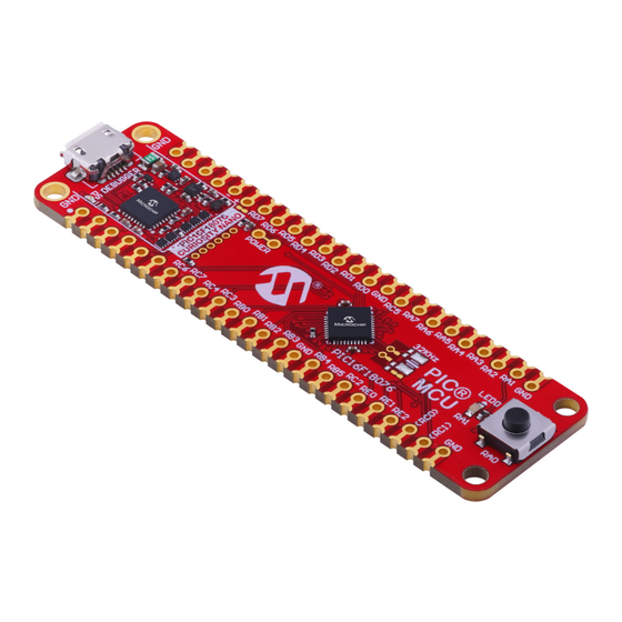
The PIC16F18076 Curiosity Nano evaluation kit is a hardware platform to evaluate microcontrollers in the
PIC16F18076 family. This board has the PIC16F18076 microcontroller (MCU) mounted.
®
Supported by MPLAB
X IDE, the board provides easy access to the features of the PIC16F18076 to explore how to
integrate the device into a custom design.
The Curiosity Nano series of evaluation boards include an on-board debugger. No external tools are necessary to
program and debug the PIC16F18076.
®
•
MPLAB
X IDE
- Software to discover, configure, develop, program, and debug Microchip microcontrollers.
•
Code examples on GitHub
•
PIC16F18076 website
•
PIC16F18076 Curiosity Nano website
©
2022 Microchip Technology Inc.
and its subsidiaries
PIC16F18076 Curiosity Nano
- Get started with code examples.
- Find documentation, data sheets, sample, and purchase microcontrollers.
- Kit information, latest user guide and design documentation.
User Guide
DS50003399A-page 1
Advertisement
Table of Contents

Related Manuals for Microchip Technology PIC16F18076


Summary of Contents for Microchip Technology PIC16F18076
-
Page 1: Preface
® Supported by MPLAB X IDE, the board provides easy access to the features of the PIC16F18076 to explore how to integrate the device into a custom design. The Curiosity Nano series of evaluation boards include an on-board debugger. No external tools are necessary to program and debug the PIC16F18076. -
Page 2: Table Of Contents
PIC16F18076 Curiosity Nano Table of Contents Preface................................1 Introduction............................. 4 1.1. Features............................4 1.2. Board Overview..........................4 Getting Started............................5 ® 2.1. Curiosity Nano Quick Start MPLAB Xpress................5 2.2. Quick Start............................5 2.2.1. Driver Installation......................5 2.2.2. Kit Window........................5 ® 2.2.3. - Page 3 PIC16F18076 Curiosity Nano 4.1.1. PIC16F18076 Curiosity Nano Pinout................24 4.1.2. Using Pin-Headers.......................25 4.2. Peripherals..........................26 4.2.1. LED..........................26 4.2.2. Mechanical Switch....................... 26 4.2.3. Crystal..........................26 4.2.4. On-Board Debugger Implementation................27 4.2.4.1. On-Board Debugger Connections............. 27 Hardware Revision History and Known Issues..................28 5.1. Identifying Product ID and Revision................... 28 5.2.
-
Page 4: Introduction
– 1.8–5.1V output voltage (limited by USB input voltage) – 500 mA maximum output current (limited by ambient temperature and output voltage) Board Overview The Microchip PIC16F18076 Curiosity Nano evaluation kit is a hardware platform to evaluate the PIC16F18076 microcontroller. Figure 1-1. PIC16F18076 Curiosity Nano Board Overview... -
Page 5: Getting Started
Connect a USB cable (Standard-A to Micro-B or Micro-AB) between the PC and the debug USB port on the board. Program your application onto the device. The PIC16F18076 device on the PIC16F18076 Curiosity Nano board is programmed and debugged by the on-board debugger. Therefore, no external programmer or debugger tool is required. 2.2.1... -
Page 6: Design Documentation And Relevant Links
Tip: The latest device family packs are available through Tools > Packs in MPLAB X IDE or online at ® Microchip MPLAB X Packs Repository. Design Documentation and Relevant Links The following list contains links to the most relevant documents and software for the PIC16F18076 Curiosity Nano board: ® ® ® ® •... -
Page 7: Curiosity Nano
A Data Gateway Interface (DGI) for code instrumentation with logic analyzer channels (debug GPIO) to visualize program flow The on-board debugger controls a Power and Status LED (marked PS) on the PIC16F18076 Curiosity Nano board. The table below shows how the different operation modes control the LED. -
Page 8: Virtual Serial Port (Cdc)
PIC16F18076 Curiosity Nano Curiosity Nano Remember: Keep the debugger’s firmware up-to-date. Firmware upgrades automatically when using ® MPLAB X IDE. 3.1.2 Virtual Serial Port (CDC) The virtual serial port (CDC) is a general purpose serial bridge between a host PC and a target device. -
Page 9: Limitations
PIC16F18076 Curiosity Nano Curiosity Nano Info: For all operating systems, use a terminal emulator that supports DTR signaling. See 3.1.2.4. Signaling. 3.1.2.3 Limitations Not all UART features are implemented in the on-board debugger CDC. The constraints are outlined here: • Baud rate: Must be in the range of 1200 bps to 500 kbps. Any baud rate outside this range will be set to the closest limit without warning. -
Page 10: Advanced Use
PIC16F18076 Curiosity Nano Curiosity Nano 3.1.2.5 Advanced Use CDC Override Mode In ordinary operation, the on-board debugger is a true UART bridge between the host and the device. However, in certain use cases, the on-board debugger can override the basic Operating mode and use the CDC TX and RX pins for other purposes. -
Page 11: Mass Storage Device
PIC16F18076 Curiosity Nano Curiosity Nano Not all UART receivers have support for detecting a break, but a correctly-formed break character usually triggers a framing error on the receiver. Sending a break character using the debugger's CDC has the following limitations: •... -
Page 12: Configuration Words
PIC16F18076 Curiosity Nano Curiosity Nano Info: STATUS.TXT is dynamically updated by the on-board debugger. The contents may be cached by the OS and, therefore, not reflecting the correct status. 3.1.3.2 Configuration Words ® Configuration Words (PIC MCU Targets) Configuration Word settings included in the project being programmed after program Flash is programmed. The debugger will not mask out any bits in the Configuration Words when writing them, but since it uses Low-Voltage Programming mode, it can't clear the LVP Configuration bit. -
Page 13: Data Gateway Interface (Dgi)
X IDE or a stand-alone application that can be ® used in parallel with MPLAB X IDE. Although DGI encompasses several physical data interfaces, the PIC16F18076 Curiosity Nano implementation includes logic analyzer channels: • One debug GPIO channel (also known as DGI GPIO) 3.1.4.1... -
Page 14: Power Supply
The USB port powers the board. It contains two LDO regulators, one to generate 3.3V for the on-board debugger and an adjustable LDO regulator for the target PIC16F18076 microcontroller and its peripherals. The voltage from a USB connector can vary between 4.4V and 5.25V (according to the USB specification) and will limit the maximum voltage supplied to the target. -
Page 15: Target Regulator
1.7V to 5.1V. Additional output voltage limits are configured in the debugger firmware to ensure that the output voltage never exceeds the hardware limits of the PIC16F18076 microcontroller. The voltage limits configured in the on-board debugger on PIC16F18076 Curiosity Nano are 1.8–... -
Page 16: External Supply
3.3.2 External Supply Instead of the on-board target regulator, an external voltage can power the PIC16F18076 Curiosity Nano. When shorting the Voltage Off (VOFF) pin to the ground (GND) pin, the on-board debugger firmware disables the target regulator, and it is safe to apply an external voltage to the VTG pin. -
Page 17: Vbus Output Pin
VBUS Output Pin PIC16F18076 Curiosity Nano has a VBUS output pin that can be used to power external components that need a 5V supply. The VBUS output pin has a PTC fuse to protect the USB against short circuits. A side effect of the PTC fuse is a voltage drop on the VBUS output with higher current loads. -
Page 18: Low-Power Measurement
Low-Power Measurement Power to the PIC16F18076 is connected from the on-board power supply and VTG pin through a 100 mil pin-header marked with “POWER” in silkscreen (J101). To measure the power consumption of the PIC16F18076 and other peripherals connected to the board, cut the Target Power strap and connect an ammeter over the strap. -
Page 19: Programming External Microcontrollers
Connections. The on-board level shifters can be completely disconnected to prevent leakage, as described 7.4. Disconnecting the On-Board Debugger. Programming External Microcontrollers The on-board debugger on PIC16F18076 Curiosity Nano can be used to program and debug microcontrollers on external hardware. 3.5.1 Supported Devices All external AVR microcontrollers with the UPDI interface can be programmed and debugged with the on-board debugger with Microchip Studio. -
Page 20: Hardware Modifications
3.5.3 Hardware Modifications The on-board debugger is connected to the PIC16F18076 by default. Remove these connections before any external microcontroller can be programmed or debugged. Cut the GPIO straps shown in the figure below with a sharp tool to disconnect the PIC16F18076 from the on-board debugger. -
Page 21: Connecting To External Microcontrollers
DBG3 is an open-drain connection and requires a pull-up resistor to function. PIC16F18076 Curiosity Nano has pull-down resistors R204 and R205 connected to the ICSP data and clock signal (DBG0 and DBG1). There is also a pull-up resistor R200 connected to the MCLR signal (DBG3). The location of pull resistors is shown in 7.2. -
Page 22: Connecting External Debuggers
Even though there is an on-board debugger, external debuggers can be connected directly to the PIC16F18076 Curiosity Nano to program/debug the PIC16F18076. When not actively used, the on-board debugger keeps all the pins connected to the PIC16F18076 and board edge in tri-state. Therefore, the on-board debugger will not interfere with any external debug tools. - Page 23 R110. If R110 is broken, the on-board debugger cannot enter the programming mode of the PIC16F18076 and will typically fail at reading the device ID. To avoid contention between the external debugger and the on-board debugger, do not start any CAUTION ®...
-
Page 24: Hardware Description
Hardware Description Hardware Description Connectors 4.1.1 PIC16F18076 Curiosity Nano Pinout All the PIC16F18076 I/O pins are accessible at the edge connectors on the board. The image below shows the board pinout. Figure 4-1. PIC16F18076 Curiosity Nano Pinout PIC16F18076 Analog Port... -
Page 25: Using Pin-Headers
Using Pin-Headers The edge connector footprint on PIC16F18076 Curiosity Nano has a staggered design where each hole is shifted 8 mil (~0.2 mm) off-center. The hole shift allows regular 100 mil pin-headers to be used without soldering on the board. -
Page 26: Peripherals
PCB. Peripherals 4.2.1 One yellow user LED is available on the PIC16F18076 Curiosity Nano board. It can be controlled by either GPIO or PWM. Driving the connected I/O line to GND can also activate the LED. Table 4-1. LED Connection... -
Page 27: On-Board Debugger Implementation
Bottom Side 4.2.4 On-Board Debugger Implementation PIC16F18076 Curiosity Nano features an on-board debugger that can be used to program and debug the PIC16F18076 using ICSP. The on-board debugger also includes a virtual serial port (CDC) interface over UART ® and debug GPIO. MPLAB X IDE can be used as a front-end for the on-board debugger for programming and debugging. -
Page 28: Hardware Revision History And Known Issues
Identifying Product ID and Revision There are two ways to find the revision and product identifier of the PIC16F18076 Curiosity Nano: Either by utilizing ® the MPLAB X IDE Kit Window or by looking at the sticker on the bottom of the PCB. -
Page 29: Document Revision History
PIC16F18076 Curiosity Nano Document Revision History Document Revision History Doc. Rev. Date Comments 09/2022 Initial document release User Guide DS50003399A-page 29 © 2022 Microchip Technology Inc. and its subsidiaries... -
Page 30: Appendix
PIC16F18076 Curiosity Nano Appendix Appendix User Guide DS50003399A-page 30 © 2022 Microchip Technology Inc. and its subsidiaries... - Page 31 Figure 7-1. PIC16F18076 Curiosity Nano MCU Schematic rotatethispage90 PIC16F18076 DEBUGGER CONNECTIONS PIC16F18076 CDC_RX CDC_RX CDC_TX Debugger Name CDC_TX DBG0 CDC TX DBG0 EUSART2 RX DBG3 DBG3 DBG1 CDC RX DBG1 EUSART2 TX DBG2 DBG2 VOFF DBG0 ICSPDAT VOFF ID_SYS ID_SYS...
- Page 32 Figure 7-2. PIC16F18076 Curiosity Nano Debugger Schematic rotatethispage90 Interface ICSP UPDI TARGET ADJUSTABLE REGULATOR TARGET TARGET TARGET Signal VCC_VBUS J100: VCC_REGULATOR VCC_LEVEL VCC_EDGE Cut-strap used for full separation of target power from the level shifters and on-board regulators. CDC TX...
-
Page 33: Assembly Drawing
PIC16F18076 Curiosity Nano Appendix Assembly Drawing Figure 7-3. PIC16F18076 Curiosity Nano Assembly Drawing Top User Guide DS50003399A-page 33 © 2022 Microchip Technology Inc. and its subsidiaries... - Page 34 PIC16F18076 Curiosity Nano Appendix Figure 7-4. PIC16F18076 Curiosity Nano Assembly Drawing Bottom User Guide DS50003399A-page 34 © 2022 Microchip Technology Inc. and its subsidiaries...
-
Page 35: Curiosity Nano Base For Click Boards
PIC16F18076 Curiosity Nano Appendix ™ Curiosity Nano Base for Click boards Figure 7-5. PIC16F18076 Curiosity Nano Pinout Mapping User Guide DS50003399A-page 35 © 2022 Microchip Technology Inc. and its subsidiaries... -
Page 36: Disconnecting The On-Board Debugger
The on-board debugger and level shifters can be completely disconnected from the PIC16F18076. The block diagram below shows all connections between the debugger and the PIC16F18076. The rounded boxes represent connections to the board edge. The signal names shown are also printed in silkscreen on the bottom side of the board. - Page 37 PIC16F18076 Curiosity Nano Appendix Figure 7-7. On-Board Debugger Connection Cut Straps GPIO straps (bottom side) Power Supply strap (top side) User Guide DS50003399A-page 37 © 2022 Microchip Technology Inc. and its subsidiaries...
-
Page 38: Microchip Information
PIC16F18076 Curiosity Nano Microchip Information The Microchip Website Microchip provides online support via our website at www.microchip.com/. This website is used to make files and information easily available to customers. Some of the content available includes: • Product Support – Data sheets and errata, application notes and sample programs, design resources, user’s guides and hardware support documents, latest software releases and archived software •... -
Page 39: Trademarks
The Adaptec logo, Frequency on Demand, Silicon Storage Technology, and Symmcom are registered trademarks of Microchip Technology Inc. in other countries. GestIC is a registered trademark of Microchip Technology Germany II GmbH & Co. KG, a subsidiary of Microchip Technology Inc., in other countries. -
Page 40: Quality Management System
PIC16F18076 Curiosity Nano Quality Management System For information regarding Microchip’s Quality Management Systems, please visit www.microchip.com/quality. User Guide DS50003399A-page 40 © 2022 Microchip Technology Inc. and its subsidiaries... -
Page 41: Worldwide Sales And Service
Tel: 631-435-6000 Sweden - Stockholm San Jose, CA Tel: 46-8-5090-4654 Tel: 408-735-9110 UK - Wokingham Tel: 408-436-4270 Tel: 44-118-921-5800 Canada - Toronto Fax: 44-118-921-5820 Tel: 905-695-1980 Fax: 905-695-2078 User Guide DS50003399A-page 41 © 2022 Microchip Technology Inc. and its subsidiaries...
Need help?
Do you have a question about the PIC16F18076 and is the answer not in the manual?
Questions and answers