
Related Manuals for protech BS-0981


Summary of Contents for protech BS-0981
- Page 1 USER MANUAL BS-0981 Fanless 19" 1U Rockmount PC with Intel® Celeron N3350 SoC BS-0981 M0...
- Page 2 BS-0981 Fanless Fanless 19" 1U Rockmount PC with Celeron N3350 SoC COPYRIGHT NOTICE & TRADEMARK All trademarks and registered trademarks mentioned herein are the property of their respective owners. This manual is copyrighted in March 2018. You may not reproduce or transmit in any form or by any means, electronic, or mechanical, including photocopying and recording.
-
Page 3: Fcc Notice
FCC NOTICE This equipment has been tested and found to comply with the limits for a Class A digital device, pursuant to part 15 of the FCC Rules. These limits are designed to provide reasonable protection against harmful interference when the equipment is operated in a commercial environment. - Page 4 Introduction This chapter provides the introduction for BS-0986 system as well as the framework of the user manual. The following topic is included: • About This Manual page 4...
- Page 5 It is not intended for general users. The following section outlines the structure of this user manual. Chapter 1 Introduction This chapter provides the introduction for the BS-0981 system as well as the framework of the user manual. Chapter 2 Getting Started This chapter describes the package contents and outlines the system specifications.
-
Page 6: Getting Started
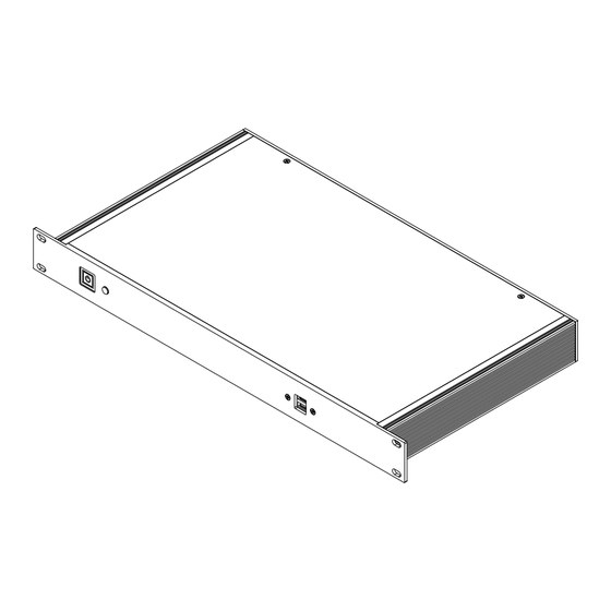
Getting Started This chapter provides the information for the BS-0981 system. It describes the package contents and outlines the system specifications. The following topics are included: • Package List • System Overview • System Diagrams • System Specification • Safety Precautions... - Page 7 System Overview Unit: mm Front View Storage indicated light Power S/W Rear View LINE OUT DC-IN Top View Unit: mm page 7...
-
Page 8: Quarter View
Quarter View Front I/O Panel Rear I/O Panel page 8... - Page 9 BS-0981 System Specifications System CPU Type Intel ApolloLake Celeron N3350 1 x SO-DIMM socket, supporting 1600 Memory Support DDR3L DRAM up to 8G (non-ECC) Hardware monitor / WatchDog Storage Support 1 x 2.5” 7mm SATAIII HDD / SSD drive space ...
- Page 10 Power Mode (1) BIOS Power Fail “On”: Boot-up when AC power returns from “Off” to “On” (default) (2) BIOS Power Fail “Off”: Non-boot-up when AC power returns from “Off” to “On” Way to boot up from S5: (1) Power Button (2) Wake-On-LAN Power Mode (3) RTC-wake...
-
Page 11: Safety Precautions
Environmental Conditions • Place your BS-0981 system on a sturdy, level surface. Be sure to allow enough space around the system to have easy access needs. • Avoid installing your system in extremely hot or cold places. -
Page 12: System Configuration
System Configuration This chapter contains helpful information about the external I/O Ports diagrams, and jumper & connector settings, and component locations for the main board. The following topics are included: • External I/O Ports Diagrams • Jumper & Connector Quick Reference Table •... - Page 13 3.1 External System I/O Ports Diagrams Front I/O Ports Diagram Storage indicated light Power S/W Rear I/O Ports Diagram LINE OUT DC-IN HDMI page 13...
- Page 14 Power Button To turn on the system, press the power button on the side of the system briefly. ACTION ASSIGNMENT Click Release +3.3V Power Button Port Name: USB Description: Dual USB 3.0 ports PIN ASSIGNMENT PIN ASSIGNMENT USB3_RXN2 USB3_RXP2 USB2_P2_DP USB3_TXN2 USB2_P2_DN USB3_TXP2...
- Page 15 DC IN 3-Pin Terminal Block Port Name: DC IN (external connector) terminal block) Description: Supports DC 12V and 16~24V power input (3-pin lockable ASSIGNMENT DC Power Input (+12V or 16~24V) DC IN VGA Port Port Name: VGA (external connector) Description: VGA Port, D-Sub 15-pin (I/O port) PIN ASSIGNMENT PIN ASSIGNMENT PIN ASSIGNMENT...
- Page 16 COM Port Port Name: COM1, COM2, COM3, COM4 (external connector) Description: COM Port Connector COM1(RS-232) Connector Pin Assignment: ASSIGNMENT ASSIGNMENT COM1_DCD COM1_DSR COM1_RX COM1_RTS COM1_TX COM1_CTS COM1_DTR COM1_RI COM1 / COM2 COM2(RS-232/422/485) Connector Pin Assignment: ASSIGNMENT RS-232 RS-422 RS-485 COM2_DCD COM2_RX COM2_TX COM2_DTR...
- Page 17 COM3(RS-232) Connector Pin Assignment: ASSIGNMENT ASSIGNMENT COM3_DCD COM3_DSR COM3_RX COM3_RTS COM3_TX COM3_CTS COM3_DTR COM3_RI_SEL COM3 / COM4 COM4(RS-232) Connector Pin Assignment: ASSIGNMENT ASSIGNMENT COM4_DCD COM4_DSR COM4_RX COM4_RTS COM4_TX COM4_CTS COM4_DTR COM4_RI_SEL Note: COM3, COM4: Pin 9 is selectable as RI, +5V or +12V according to jumper setting. Default setting is RI, please see “COM3 and COM4 PIN9 Definition Selection Guide”...
-
Page 18: Lan Led Status
3.5.6 LAN Port Port Name: LAN1, LAN2 (external connector) Description: LAN RJ-45 Ports LAN1 / LAN2 LAN1 Pin Assignment LAN2 Pin Assignment PIN ASSIGNMENT PIN ASSIGNMENT LAN1_MDIP0 LAN2_MDIP0 LAN1_MDIN0 LAN2_MDIN0 LAN1_MDIP1 LAN2_MDIP1 LAN1_MDIP2 LAN2_MDIP2 LAN1_MDIN2 LAN2_MDIN2 LAN1_MDIN1 LAN2_MDIN1 LAN1_MDIP3 LAN2_MDIP3 LAN1_MDIN3 LAN2_MDIN3 LAN LED Status... -
Page 19: Component Locations Of System Main Board
Component Locations of System Main Board Top View of System Main Board Mini PCIe Figure 3-1 Main Board Component Location (Top View) WARNING: Always disconnect the power cord when you are working with connectors and jumpers on the main board. Make sure both the system and peripheral devices are turned OFF as sudden surge of power could damage sensitive components. - Page 20 Jumper Setting and Connector Location of System Main Board VGA1 COM3 Pin9 RI/5V/12V LAN2 LAN1 HDMI1 USB2 USB1 6 5 6 5 JP_COM3 JP_COM4 (default) 2 1 2 1 COM4 JI2C1 COM4 Pin9 RI/5V/12V JLPC1 JMCU1 COM3 JDIO1 COM2 (default) SATA_PWR1 M_SATA1 COM1...
- Page 21 How To Set Jumpers You can configure your board by setting jumpers. Jumper is consists of two or three metal pins with a plastic base mounted on the card, and by using a small plastic "cap", Also known as the jumper cap (with a metal contact inside), you are able to connect The jumper can be combined into sets that called jumper blocks.
-
Page 22: Jumper Settings
Jumper Diagrams Jumper Settings 2 pin Jumper close(enabled) Looks like this 3 pin Jumper 2-3 pin close(enabled) Looks like this Jumper Block 1-2 pin close(enabled) Looks like this page 22... - Page 23 Setting Connectors and Jumpers COM3 and COM4 PIN9 Definition Selection Guide Jumper Name: JP_COM3, JP_COM4 Description: COM3 and COM4 Port pin9 RI/5V/12V Selection SELECTION JUMPER SETTING JUMPER ILLUSTRATION (Default Setting) JP_COM3 JP_COM4 +12V JP_COM3 JP_COM4 JP_COM4 JP_COM3 page 23...
-
Page 24: Usb 2.0 Port
GPI/GPO 7 JDIO1 Notes: Users can set the GPI/GPO configuration via Protech’s API/Utility. Default setting is GPI every time when system AC power is re-applied from power failure state Configuration can still be kept even in S5 state unless system AC power is lost. - Page 25 I2C Wafer Port Name: JI2C1 Description: I2C Wafer (no use for this system) PIN ASSIGNMENT VCC5 I2C0_SCL_33 I2C0_SDA_33 JI2C1 MCU FW Rewrite Connector Port Name: JMCU1 Description: MCU FW Rewrite Connector for engineering use only PIN ASSIGNMENT MCU_5VSB JMCU1 MCU_SPD MCU_SPC page 25...
-
Page 26: Dc Power Input Connector
System Fan Connector Port Name: FAN1 Description: System Fan Connector (no use for this system) PIN ASSIGNMENT VCC12 SYSFANIN SYSFANOUT FAN1 DC Power Input Connector Port Name: PWR2 Description: DC Power Input Connector PIN ASSIGNMENT PIN ASSIGNMENT VCC12 VCC12 PWR2 Note: The voltage of input power should be 12V or 16~24V. - Page 27 Mini PCI Express Slot Name: M_PCIE1 Description: Mini PCI Express Slot ASSIGNMENT ASSIGNMENT PCIE_WAKEJ V3P3S Reserved Reserved VCC1_5 M_CLKREQJ Reserved Reserved M_PCIE_CLKN Reserved M_PCIE_CLKP Reserved Reserved Reserved Reserved Reserved PMU_PLTRST_N PCIE_P2_RXN V3_3SB PCIE_P2_RXP VCC1_5 SMB_3P3_SCL M_PCIE1 PCIE_P2_TXN SMB_3P3_SDA PCIE_P2_TXP USB2_P7_DN USB2_P7_DP V3P3S V3P3S...
-
Page 28: Msata Connector
mSATA Connector Port Name: M_SATA1 Description: mSATA Slot (An USB type mPCIe card is supported.) ASSIGNMENT ASSIGNMENT V3P3S_MSATA SATA_RXP1 V3P3S_MSATA SATA_RXN1 M_SATA1 SATA_TXN1 SATA_TXP1 USB2_P0_DN USB2_P0_DP V3P3S_MSATA V3P3S_MSATA V3P3S_MSATA page 28... - Page 29 LVDS Connector Port Name: LVDS1 Description: LVDS Connector (no use for this system) ASSIGNMENT ASSIGNMENT LVDS_VCC LVDS_CLKB_DP LVDS_CLKB_DN LVDS_B2_DN LVDS_B2_DP LVDS_B1_DP LVDS_B1_DN LVDS_B3_DN LVDS_B3_DP LVDS_B0_DN LVDS_B0_DP LVDS_CLKA_DP LVDS_CLKA_DN LVDS_A2_DN LVDS_A2_DP LVDS1 LVDS_A1_DP LVDS_A1_DN LVDS_A0_DN LVDS_A0_DP LVDS_A3_DN LVDS_A3_DP LVDS_VCC LVDS_VCC page 29...
- Page 30 Slide Switch For LVDS Resolution Selection (no use for this system) Jumper Name: SW1 Description: Slide Switch for LVDS Resolution/Channel/Color Bit Selection SELECTION SETTING 800 x 600 1CH/18bit (Default Setting) 1024 x 768 1CH/18bit 1024 x 768 1CH/24bit 1280 x 768 1CH/18bit 1280 x 800 1CH/18bit...
- Page 31 SELECTION SETTING 1280 x 960 1CH/18bit 1280 x 1024 2CH/24bit 1366 x 768 1CH/18bit 1366 x 768 1CH/24bit 1440 x 900 2CH/24bit 1400 x 1050 2CH/24bit page 31...
- Page 32 SELECTION SETTING 1600 x 900 2CH/24bit 1680 x 1050 2CH/24bit 1600 x 1200 2CH/24bit 1920 x 1080 2CH/24bit 1920 x 1200 2CH/24bit page 32...
-
Page 33: Front Panel Connector
Front Panel Connector Port Name: JFP1 Description: Front Panel Connector ASSIGNMENT ASSIGNMENT HDD LED+ POWER LED+ HDD LED- RESET BTN JFP1 POWER BTN HD Audio Connector Port Name: AUDIO1 Description: HD Audio Connector for Line In / Line Out / Mic In. ASSIGNMENT ASSIGNMENT LINE-OUT-L... - Page 34 Panel Inverter Connector Port Name: JINV1 Description: Panel Inverter Connector (no use for this system) ASSIGNMENT VCC12 VCC12 LVDS_BKLCTL JINV1 LVDS_BKLTEN SATA 3.0 Connector Port Name: SATA1 Description: Serial ATA 3.0 Connector ASSIGNMENT SATA_TXP0 SATA_TXN0 SATA1 SATA_RXN0 SATA_RXP0 SATA Power Connector Port Name: SATA1_PWR1 Description: Serial ATA Power Connector...
- Page 35 LVDS Backlight Control Selection (no use for this system) Jumper Name: JP7 Description: Jumper for selecting PIN4 (LVDS_BKLCTL) voltage of JINV1. SELECTION JUMPER SETTING JUMPER ILLUSTRATION 3.3V (Default Setting) LVDS VCC Voltage Selection Jumper Name: JP_VDD1 Description: Voltage selection jumper for selecting PIN1, PIN29, PIN30 (LVDS_VCC) voltage of LVDS1.
- Page 36 Clear CMOS Data Selection Jumper Name: JP4 Description: Clear CMOS Data Selection Step1. Remove the main power of the PC. Step2. Close JP4 (pins 1-2) for 6 seconds by a cap. Step3. Remove the cap which is just used on JP4 (1-2), so that JP4 returns to “OPEN”.
-
Page 37: Software Utilities
Software Utilities This chapter provides the detailed information that guides users to install driver utilities for the system. The following topics are included: ® • Installing Intel Chipset Software Installation Utility • Installing Graphics Driver Utility • Installing LAN Driver Utility •... - Page 38 Introduction Enclosed with the BS-E097 Series package is our driver utilities contained in a DVD-ROM disk. Refer to the following table for driver locations: Filename Win10 (Assume that DVD-ROM Purpose Shell 64-bit drive is D:) D:\Driver\Flash BIOS For Aptio(EFI) BIOS update utility Intel(R) Chipset Device Software ...
-
Page 39: Installing Intel ® Chipset Software Installation Utility
® Installing Intel Chipset Software Installation Utility Introduction ® The Intel Chipset Software Installation Utility installs the Windows *.INF files to the target system. These files outline to the operating system how to configure the Intel chipset components in order to ensure that the following functions work properly: •... -
Page 40: Installing Graphics Driver Utility
Installing Graphics Driver Utility The GRAPHICS interface embedded in BS-E097 can support a wide range of display types. To install the Graphics driver utility, follow the steps below: Connect the USB DVD-ROM device to BS-E097 and insert the driver disk. Enter the VGA folder where the driver is located. -
Page 41: Installing Lan Driver Utility
Installing LAN Driver Utility Enhanced with LAN function, BS-E097 supports various network adapters. To install the LAN Driver, follow the steps below: Connect the USB DVD-ROM device to BS-E097 and insert the driver disk. Enter the LAN folder where the driver is located. Click Setup.exe file for driver installation. -
Page 42: Installing Sound Driver Utility
Installing Sound Driver Utility The sound function enhanced in this system is fully compatible with ® Windows 10 64bit. To install the Sound Driver, follow the steps below: Connect the USB DVD-ROM device to BS-E097 and insert the driver disk. Open the Sound folder where the driver is located. -
Page 43: Installing Intel ® Serial I/O Driver Utility
® Installing Intel Serial I/O Driver Utility To install the Serial I/O Driver, follow the steps below: Connect the USB DVD-ROM device to BS-E097 and insert the driver disk. Open the Serial I/O folder where the driver is located. Select Windows 10 (64-bit) for your OS platform. Click the SetupSerialIO.exe file for driver installation. - Page 44 Microsoft Hotfix KB3211320 and KB3213986 Driver Installation Introduction The Microsoft Hotfix kb3211320 and kb3213986 Driver that needs to be installed depends on the system's specific hardware and firmware features. The installer, compatible with Windows 10, detects the system's capabilities and installs the relevant drivers and applications. Installation Instructions for Windows 10 To install the utility, simply follow the following steps: Insert the driver disk into a DVD ROM device.
-
Page 45: Bios Setup
BIOS SETUP This chapter guides users how to configure the basic system configurations via the BIOS Setup Utilities. The information of the system configuration is saved in battery-backed CMOS RAM and BIOS NVRAM so that the Setup information is retained when the system is powered off. - Page 46 Introduction The BS-E097 System uses an AMI (American Megatrends Incorporated) Aptio BIOS that is stored in the Serial Peripheral Interface Flash Memory (SPI Flash) and can be updated. The SPI Flash contains the built-in BIOS setup program, Power-On Self-Test (POST), PCI auto-configuration utility, LAN EEPROM information, and Plug and Play support.
- Page 47 system and allows technicians to troubleshoot the occurred errors when the hardware is faulty. The BIOS setup menu allows users to view and modify the BIOS settings for the computer. After the system is powered on, users can access the BIOS setup menu by pressing <Del>...
-
Page 48: Accessing Setup Utility
Accessing Setup Utility After the system is powered on, BIOS will enter the Power-On Self-Test (POST) routines and the POST message will be displayed: Figure 5-2. POST Screen with AMI Logo Press <Del> or <Esc> to access the Setup Utility program and the Main menu of the Aptio Setup Utility will appear on the screen as below: page 48... - Page 49 BIOS Setup Menu Initialization Screen You may move the cursor by <↑> and <↓> keys to highlight the individual menu items. As you highlight each item, a brief description of the highlighted selection will appear on the right side of the screen. The language of the BIOS setup menu interface and help messages are shown in US English.
- Page 50 Main Menu Path Main The Main menu allows you to view the BIOS Information, change the system date and time, and view the user access privilege level. Use tab to switch between date elements. Use <↑> or <↓> arrow keys to highlight the item and enter the value you want in each item.
- Page 51 BIOS Setting Options Description/Purpose TXE FW No changeable options Displays the TXE FW version. No changeable options Displays the GOP version. System Date Month, day, year Sets the system date. The format is [Day Month/ Date/ Year]. Users can directly enter values or use <+>...
- Page 52 Advanced Menu Path Advanced This menu provides advanced configurations such as ACPI Settings, Onboard Device Configuration, Hardware Monitor, F81964 Watchdog, S5 RTC Wake Settings, CPU Configuration, F81964 Super IO Configuration, USB Configuration and Platform Trust Technology. Advanced Menu Screen BIOS Setting Options Description/Purpose ACPI Settings...
-
Page 53: Advanced - Acpi Settings
5.4.1 Advanced - ACPI Settings Menu Path Advanced > ACPI Settings The ACPI Settings allows users to configure relevant ACPI (Advanced Configuration and Power Management Interface) settings, such as Hibernation (S4) and Enable Sleep (S3). ACPI Settings Screen BIOS Setting Options Description/Purpose Enables or Disables System ability to... -
Page 54: Advanced - Onboard Device Configuration
5.4.2 Advanced – Onboard Device Configuration Menu Path Advanced > Onboard Device Configuration Onboard Device Configuration Screen BIOS Setting Options Description/Purpose - RS-422 COM2 Mode Selection - RS-232 (default) Selects COM2 mode. - RS-485 page 54... -
Page 55: Advanced - Hardware Monitor
5.4.3 Advanced – Hardware Monitor Menu Path Advanced > Hardware Monitor The Hardware Monitor allows users to monitor the health and status of the system such as CPU temperature, system temperature, system fan speed and voltage levels in supply. Hardware Monitor Screen BIOS Setting Options Description/Purpose... - Page 56 5.4.4 Advanced - F81964 Watchdog Menu Path Advanced > F81964 Watchdog If the system hangs or fails to respond, enable the F81964 watchdog function to trigger a system reset via the 255-level watchdog timer. F81964 Watchdog Screen BIOS Setting Options Description/Purpose - Disabled (default) Enables/Disables 81964 Watchdog...
-
Page 57: Advanced - S5 Rtc Wake Settings
5.4.5 Advanced - S5 RTC Wake Settings Advanced > S5 RTC Wake Settings Menu Path The S5 RTC Wake Settings enables/disables the system to wake up at a preset time of a day from S5 State using RTC alarm. S5 RTC Wake Settings Screen BIOS Setting Options Description/Purpose... - Page 58 5.4.5.1 S5 RTC Wake Settings [Fixed Time] Menu Path Advanced > S5 RTC Wake Settings [Fixed Time] S5 RTC Wake Settings Screen (Fixed Time) BIOS Setting Options Description/Purpose Sets an hour for a scheduled Wake up hour (Numeric) from 0 to 23 power-on event.
-
Page 59: S5 Rtc Wake Settings [Dynamic Time]
5.4.5.2 S5 RTC Wake Settings [Dynamic Time] Menu Path Advanced > S5 RTC Wake Settings [Dynamic Time] S5 RTC Wake Settings Screen (Dynamic Time) BIOS Setting Options Description/Purpose Sets a period of time (in minutes) after Wake up minute increase (Numeric) from 1 to 5 which the board wakes up from S5 state. -
Page 60: Advanced - Cpu Configuration
5.4.6 Advanced - CPU Configuration Menu Path Advanced > CPU Configuration The CPU Configuration provides advanced CPU settings such as CPU power management and some information about CPU. CPU Configuration Screen BIOS Setting Options Description/Purpose Socket 0 CPU Information Sub-Menu Soket specific CPU Information. - Page 61 5.4.6.1 CPU Configuration - Socket 0 CPU Information Menu Path Advanced > CPU Configuration > Socket 0 CPU Information Socket 0 CPU Information Screen BIOS Setting Options Description/Purpose CPU Branding String No changeable options Displays CPU Branding String. CPU Signature No changeable options Displays CPU Signature.
- Page 62 5.4.6.2 CPU Configuration - CPU Power Management Configuration Menu Path Advanced > CPU Configuration > CPU Power Management Configuration CPU Power Management Configuration Screen BIOS Setting Options Description/Purpose Enables/Disables Intel SpeedStep - Disabled EIST feature for dynamic scaling processor - Enabled (default) frequency.
- Page 63 5.4.7 Advanced - F81964 Super IO Configuration Menu Path Advanced > F81964 Super IO Configuration The F81964 Super IO Configuration allows users to configure the serial ports 1-4. F81964 Super IO Configuration Screen BIOS Setting Options Description/Purpose Super IO Chip (F81964) No changeable options Displays the super I/O chip model.
- Page 64 5.4.7.1 F81964 Super IO Configuration - Serial Port 1 Configuration Menu Path Advanced > F81964 Super IO Configuration > Serial Port 1 Configuration Serial Port 1 Configuration Screen BIOS Setting Options Description/Purpose - Disabled Serial Port Enables/Disables COM1. - Enabled (default) Device Settings No changeable options Reports the current COM setting.
- Page 65 5.4.7.2 F81964 Super IO Configuration - Serial Port 2 Configuration Menu Path Advanced > F81964 Super IO Configuration > Serial Port 2 Configuration Serial Port 2 Configuration Screen BIOS Setting Options Description/Purpose - Disabled Serial Port Enables/Disables COM2. - Enabled (default) Device Settings No changeable options Reports the current COM setting.
- Page 66 5.4.7.3 F81964 Super IO Configuration - Serial Port 3 Configuration Menu Path Advanced > F81964 Super IO Configuration > Serial Port 3 Configuration Serial Port 3 Configuration Screen BIOS Setting Options Description/Purpose - Disabled Serial Port Enables/Disables COM3. - Enabled (default) Device Settings No changeable options Reports the current COM setting.
- Page 67 5.4.7.4 F81964 Super IO Configuration - Serial Port 4 Configuration Menu Path Advanced > F81964 Super IO Configuration > Serial Port 4 Configuration Serial Port 4 Configuration Screen BIOS Setting Options Description/Purpose - Disabled Serial Port Enable/Disable COM4. - Enabled (default) Device Settings No changeable options Reports the current COM setting.
-
Page 68: Advanced - Usb Configuration
5.4.8 Advanced - USB Configuration Menu Path Advanced > USB Configuration The USB Configuration allows users to configure advanced USB settings such as USB mass storage driver support and mass storage devices. USB Configuration Screen BIOS Setting Options Description/Purpose USB Module Version No changeable options Displays USB module version. -
Page 69: Advanced - Platform Trust Technology
Platform Trust Technology 5.4.9 Advanced - Menu Path Advanced > Platform Trust Technology The Platform Trust Technology allows users to configure advanced TPM settings such as fTPM. Platform Trust Technology Screen BIOS Setting Options Description/Purpose Enables or Disables fTPM. - Disabled fTPM It must be disabled when discrete TPM - Enabled... - Page 70 Chipset Menu Path Chipset This menu allows users to configure advanced Chipset settings such as North Bridge and South Bridge configuration parameters. Chipset Screen BIOS Setting Options Description/Purpose North Bridge Sub-menu North Bridge Parameters. South Bridge Sub-menu South Bridge Parameters. page 70...
-
Page 71: Chipset - North Bridge
5.5.1 Chipset - North Bridge Menu Path Chipset > North Bridge North Bridge Screen BIOS Setting Options Description/Purpose Displays the current amount and Total Memory No changeable options type of memory on the system, e.g. "8192 MB (LPDDR3)". Memory Speed No changeable options Displays memory speed. -
Page 72: Chipset - South Bridge
5.5.2 Chipset - South Bridge Menu Path Chipset > South Bridge South Bridge Screen BIOS Setting Options Description/Purpose HD-Audio Configuration Sub-Menu HD-Audio configuration settings. LPSS Configuration Sub-Menu LPSS configuration settings. PCI Express Configuration Sub-Menu PCI Express configuration settings. SATA Drives Sub-Menu SATA Drives configuration settings. -
Page 73: South Bridge - Hd-Audio Configuration
5.5.2.1 South Bridge - HD-Audio Configuration Menu Path Chipset > South Bridge > HD-Audio Configuration HD-Audio Configuration Screen BIOS Setting Options Description/Purpose - Disabled HD-Audio Support Enables/Disables HD-Audio support. - Enabled (default) page 73... -
Page 74: South Bridge - Lpss Configuration
5.5.2.2 South Bridge - LPSS Configuration Menu Path Chipset > South Bridge > LPSS Configuration LPSS Configuration Screen BIOS Setting Options Description/Purpose LPSS I2C #1 Support - Disable Enables/Disables LPSS I2C #1 (D22:F0) - PCI Mode (default) support. - Standard Mode - Fast Mode (default) Set LPSS I2C #1 Speed Selects LPSS I2C #1 speed. -
Page 75: South Bridge - Pci Express Configuration
5.5.2.3 South Bridge - PCI Express Configuration Menu Path Chipset > South Bridge > PCI Express Configuration PCI Express Configuration Screen BIOS Setting Options Description/Purpose PCI E Express Root Port 1 Sub-Menu PCIE RP1 parameters (I210 LAN). (I210 LAN) PCI E Express Root Port 2 Sub-Menu PCIE RP2 parameters (I210 LAN). - Page 76 South Bridge - PCI Express Configuration - PCI Express Root Port 1 (I210 LAN) Menu Path Chipset > South Bridge > PCI Express Configuration > PCI Express Root Port 1(I210 LAN) PCI Express Root Port 1 (I210 LAN) Screen BIOS Setting Options Description/Purpose - Disable...
- Page 77 South Bridge - PCI Express Configuration - PCI Express Root Port 2 (I210 LAN) Menu Path Chipset > South Bridge > PCI Express Configuration > PCI Express Root Port 2(I210 LAN) PCI Express Root Port 2(I210 LAN) Screen BIOS Setting Options Description/Purpose - Disable...
- Page 78 South Bridge - PCI Express Configuration - PCI Express Root Port 3 (Mini-PCIe) Menu Path Chipset > South Bridge > PCI Express Configuration > PCI Express Root Port 3 (Mini-PCIe) PCI Express Root Port 3 (Mini-PCIe) Screen BIOS Setting Options Description/Purpose - Disable PCI Express Root Port 3...
-
Page 79: South Bridge - Sata Drives
5.5.2.4 South Bridge - SATA Drives Menu Path Chipset > South Bridge > SATA Drives SATA Drives Screen BIOS Setting Options Description/Purpose - Enabled (default) Enables/Disables the chipset SATA Chipset SATA - Disabled controller. Displays SATA drive branding SATA Port 0 No changeable options information if device exists on port 0. -
Page 80: South Bridge - Miscellaneous Configuration
5.5.2.5 South Bridge - Miscellaneous Configuration Menu Path Chipset > South Bridge > Miscellaneous Configuration Miscellaneous Configuration Screen BIOS Setting Options Description/Purpose Specifies what state to go to when power is re-applied after a power failure (G3 state). -Power On (default) •... - Page 81 Security Menu Path Security From the Security menu, you are allowed to create, change or clear the administrator password. You will be asked to enter the configured administrator password before you can access the Setup Utility. By setting an administrator password, you will prevent other users from changing your BIOS settings.
- Page 82 BIOS Setting Options Description/Purpose Password can be 3-20 User Password Specifies the user password. alphanumeric characters. Enter sub-menu with option to enabled password protected HDD Security Configuration Sub-Menu HDD/SSD (if supported by SATA device). Create an Administrator or User Password Select the Administrator Password / User Password option from the Security menu and press <Enter>, and the password dialog entry box appears.
- Page 83 Boot Menu Path Boot This menu provides control items for setting system boot configuration and boot priorities. Boot Screen BIOS Setting Options Description/Purpose Number of seconds to wait for setup Setup Prompt Timeout (Numeric) from 1 to 65535. activation key. Selects the NumLock state after the system is powered on.
- Page 84 BIOS Setting Options Description/Purpose When quite boot is enabled, it - Disabled (default) displays AMI or OEM logo (if Quiet Boot - Enabled implemented) instead of POST messages during the boot. - Disabled (default) Enables or Disables Fast Boot Fast Boot - Enabled Options.
-
Page 85: Save And Exit
Save & Exit Menu Path Save & Exit The Save & Exit allows users to save or discard changed BIOS settings as well as load factory default settings. Save Changed BIOS Settings To save and validate the changed BIOS settings, select Save Changes from the Save &... - Page 86 BIOS Setting Options Description/Purpose Exits and saves the changes in Save Changes and Exit No changeable options NVRAM. Exits without saving any changes Discard Changes and Exit No changeable options made in BIOS settings. Saves the changes in NVRAM and Save Changes and Reset No changeable options resets.
-
Page 87: Appendix A System Diagrams
Appendix A System Diagrams This appendix provides exploded diagrams and part numbers of BS-E097 system. The following topics are included: • BS-E097 System Exploded Diagram • BS-E097 SATA HDD Exploded Diagram • BS-E097 Stand Exploded Diagram page 87... - Page 88 BS-0981 System Exploded Diagram (27) 90-004-01400000 (28) 22-215-40006011 page 88...
- Page 89 80-005-01002452 80-005-01006406 80-005-01004452 page 89...
-
Page 90: Appendix B Technical Summary
Appendix B Technical Summary This appendix will give you a brief introduction of the allocation maps for BS-E097 resources. The following topics are included: • Interrupt Map • I/O Map • Memory Map • Configuring WatchDog Timer • Flash BIOS Update page 90... -
Page 91: Interrupt Map
Interrupt Map Assignment IRQ 0 System timer IRQ 3 Communications Port (COM2) IRQ 4 Communications Port (COM1) IRQ 7 Communications Port (COM3) IRQ 8 System CMOS/real time clock IRQ 10 Communications Port (COM4) IRQ 25 High Definition Audio Controller IRQ 27 Intel(R) Serial IO I2C Host Controller - 5AAC IRQ 54 Microsoft ACPI-Compliant System... - Page 92 Assignment IRQ 77 Microsoft ACPI-Compliant System IRQ 78 Microsoft ACPI-Compliant System IRQ 79 Microsoft ACPI-Compliant System IRQ 80 Microsoft ACPI-Compliant System IRQ 81 Microsoft ACPI-Compliant System IRQ 82 Microsoft ACPI-Compliant System IRQ 83 Microsoft ACPI-Compliant System IRQ 84 Microsoft ACPI-Compliant System IRQ 85 Microsoft ACPI-Compliant System IRQ 86...
- Page 93 Assignment IRQ 110 Microsoft ACPI-Compliant System IRQ 111 Microsoft ACPI-Compliant System IRQ 112 Microsoft ACPI-Compliant System IRQ 113 Microsoft ACPI-Compliant System IRQ 114 Microsoft ACPI-Compliant System IRQ 115 Microsoft ACPI-Compliant System IRQ 116 Microsoft ACPI-Compliant System IRQ 117 Microsoft ACPI-Compliant System IRQ 118 Microsoft ACPI-Compliant System IRQ 119...
- Page 94 Assignment IRQ 143 Microsoft ACPI-Compliant System IRQ 144 Microsoft ACPI-Compliant System IRQ 145 Microsoft ACPI-Compliant System IRQ 146 Microsoft ACPI-Compliant System IRQ 147 Microsoft ACPI-Compliant System IRQ 148 Microsoft ACPI-Compliant System IRQ 149 Microsoft ACPI-Compliant System IRQ 150 Microsoft ACPI-Compliant System IRQ 151 Microsoft ACPI-Compliant System IRQ 152...
- Page 95 Assignment IRQ 176 Microsoft ACPI-Compliant System IRQ 177 Microsoft ACPI-Compliant System IRQ 178 Microsoft ACPI-Compliant System IRQ 179 Microsoft ACPI-Compliant System IRQ 180 Microsoft ACPI-Compliant System IRQ 181 Microsoft ACPI-Compliant System IRQ 182 Microsoft ACPI-Compliant System IRQ 183 Microsoft ACPI-Compliant System IRQ 184 Microsoft ACPI-Compliant System IRQ 185...
- Page 96 Assignment IRQ 260 Microsoft ACPI-Compliant System IRQ 261 Microsoft ACPI-Compliant System IRQ 262 Microsoft ACPI-Compliant System IRQ 263 Microsoft ACPI-Compliant System IRQ 264 Microsoft ACPI-Compliant System IRQ 265 Microsoft ACPI-Compliant System IRQ 266 Microsoft ACPI-Compliant System IRQ 267 Microsoft ACPI-Compliant System IRQ 268 Microsoft ACPI-Compliant System IRQ 269...
- Page 97 Assignment IRQ 293 Microsoft ACPI-Compliant System IRQ 294 Microsoft ACPI-Compliant System IRQ 295 Microsoft ACPI-Compliant System IRQ 296 Microsoft ACPI-Compliant System IRQ 297 Microsoft ACPI-Compliant System IRQ 298 Microsoft ACPI-Compliant System IRQ 299 Microsoft ACPI-Compliant System IRQ 300 Microsoft ACPI-Compliant System IRQ 301 Microsoft ACPI-Compliant System IRQ 302...
- Page 98 Assignment IRQ 326 Microsoft ACPI-Compliant System IRQ 327 Microsoft ACPI-Compliant System IRQ 328 Microsoft ACPI-Compliant System IRQ 329 Microsoft ACPI-Compliant System IRQ 330 Microsoft ACPI-Compliant System IRQ 331 Microsoft ACPI-Compliant System IRQ 332 Microsoft ACPI-Compliant System IRQ 333 Microsoft ACPI-Compliant System IRQ 334 Microsoft ACPI-Compliant System IRQ 335...
- Page 99 Assignment IRQ 359 Microsoft ACPI-Compliant System IRQ 360 Microsoft ACPI-Compliant System IRQ 361 Microsoft ACPI-Compliant System IRQ 362 Microsoft ACPI-Compliant System IRQ 363 Microsoft ACPI-Compliant System IRQ 364 Microsoft ACPI-Compliant System IRQ 365 Microsoft ACPI-Compliant System IRQ 366 Microsoft ACPI-Compliant System IRQ 367 Microsoft ACPI-Compliant System IRQ 368...
- Page 100 Assignment IRQ 392 Microsoft ACPI-Compliant System IRQ 393 Microsoft ACPI-Compliant System IRQ 394 Microsoft ACPI-Compliant System IRQ 395 Microsoft ACPI-Compliant System IRQ 396 Microsoft ACPI-Compliant System IRQ 397 Microsoft ACPI-Compliant System IRQ 398 Microsoft ACPI-Compliant System IRQ 399 Microsoft ACPI-Compliant System IRQ 400 Microsoft ACPI-Compliant System IRQ 401...
- Page 101 Assignment IRQ 425 Microsoft ACPI-Compliant System IRQ 426 Microsoft ACPI-Compliant System IRQ 427 Microsoft ACPI-Compliant System IRQ 428 Microsoft ACPI-Compliant System IRQ 429 Microsoft ACPI-Compliant System IRQ 430 Microsoft ACPI-Compliant System IRQ 431 Microsoft ACPI-Compliant System IRQ 432 Microsoft ACPI-Compliant System IRQ 433 Microsoft ACPI-Compliant System IRQ 434...
- Page 102 Assignment IRQ 458 Microsoft ACPI-Compliant System IRQ 459 Microsoft ACPI-Compliant System IRQ 460 Microsoft ACPI-Compliant System IRQ 461 Microsoft ACPI-Compliant System IRQ 462 Microsoft ACPI-Compliant System IRQ 463 Microsoft ACPI-Compliant System IRQ 464 Microsoft ACPI-Compliant System IRQ 465 Microsoft ACPI-Compliant System IRQ 466 Microsoft ACPI-Compliant System IRQ 467...
- Page 103 Assignment IRQ 491 Microsoft ACPI-Compliant System IRQ 492 Microsoft ACPI-Compliant System IRQ 493 Microsoft ACPI-Compliant System IRQ 494 Microsoft ACPI-Compliant System IRQ 495 Microsoft ACPI-Compliant System IRQ 496 Microsoft ACPI-Compliant System IRQ 497 Microsoft ACPI-Compliant System IRQ 498 Microsoft ACPI-Compliant System IRQ 499 Microsoft ACPI-Compliant System IRQ 500...
- Page 104 Assignment Intel(R) USB 3.0 eXtensible Host Controller - 1.0 IRQ 4294967289 (Microsoft) IRQ 4294967290 Intel(R) Trusted Execution Engine Interface IRQ 4294967291 Intel(R) HD Graphics IRQ 4294967292 Standard SATA AHCI Controller Intel(R) Celeron(R)/Pentium(R) Processor PCI Express IRQ 4294967293 Root Port - 5AD9 Intel(R) Celeron(R)/Pentium(R) Processor PCI Express IRQ 4294967294 Root Port - 5AD8...
- Page 105 I/O MAP I/O Map Assignment 0x00000000-0x0000006F PCI Express Root Complex 0x00000020-0x00000021 Programmable interrupt controller 0x00000024-0x00000025 Programmable interrupt controller 0x00000028-0x00000029 Programmable interrupt controller 0x0000002C-0x0000002D Programmable interrupt controller 0x0000002E-0x0000002F Motherboard resources 0x00000030-0x00000031 Programmable interrupt controller 0x00000034-0x00000035 Programmable interrupt controller 0x00000038-0x00000039 Programmable interrupt controller 0x0000003C-0x0000003D Programmable interrupt controller 0x00000040-0x00000043...
- Page 106 I/O Map Assignment 0x00000500-0x000005FE Motherboard resources 0x00000600-0x0000061F Motherboard resources 0x00000680-0x0000069F Motherboard resources 0x00000A00-0x00000A0F Motherboard resources 0x00000A10-0x00000A1F Motherboard resources 0x00000A20-0x00000A2F Motherboard resources 0x00000D00-0x0000FFFF PCI Express Root Complex 0x0000164E-0x0000164F Motherboard resources Intel(R) Celeron(R)/Pentium(R) Processor 0x0000D000-0x0000DFFF PCI Express Root Port - 5AD9 Intel(R) Celeron(R)/Pentium(R) Processor 0x0000E000-0x0000EFFF PCI Express Root Port - 5AD8 0x0000F000-0x0000F03F...
-
Page 107: Memory Map
Memory Map Memory Map Assignment 0xE0000000-0xEFFFFFFF Motherboard resources 0xE0000000-0xEFFFFFFF PCI Express Root Complex 0xFEA00000-0xFEAFFFFF Motherboard resources 0xFED01000-0xFED01FFF Motherboard resources 0xFED03000-0xFED03FFF Motherboard resources 0xFED06000-0xFED06FFF Motherboard resources 0xFED08000-0xFED09FFF Motherboard resources 0xFED80000-0xFEDBFFFF Motherboard resources 0xFED1C000-0xFED1CFFF Motherboard resources 0xFEE00000-0xFEEFFFFF Motherboard resources 0x91310000-0x91313FFF High Definition Audio Controller 0x91000000-0x910FFFFF High Definition Audio Controller Intel(R) Celeron(R)/Pentium(R) Processor... - Page 108 Memory Map Assignment 0x80000000-0x8FFFFFFF Intel(R) HD Graphics 0x91314000-0x91315FFF Standard SATA AHCI Controller 0x9131A000-0x9131A0FF Standard SATA AHCI Controller 0x91319000-0x913197FF Standard SATA AHCI Controller 0x7B800001-0x7BFFFFFF PCI Express Root Complex 0x7C000001-0x7FFFFFFF PCI Express Root Complex page 108...
-
Page 109: Configuring Watchdog Timer
Configuring WatchDog Timer The I/O port address of the watchdog timer is 2E (hex) and 2F (hex). 2E (hex) is the address port. 2F (hex) is the data port. User must first assign the address of register by writing address value into address port 2E (hex), then write/read data to/from the assigned register through data port 2F (hex). - Page 110 Code example for watch dog timer Enable the watchdog timer and set the timeout interval to 30 seconds. Enter to extended function mode ; ------------------------- ------------------------------- ; ------------------ Select Logical Device 7 of watchdog timer ------------ ;-------------------------- Enable Watch dog feature -------------------------- ;...
- Page 111 ;------------------------- Set second as counting unit -------------------------- ;--------------------------- Start the watchdog timer --------------------------- ;----------------------Exit the extended function mode ----------------------- page 111...
-
Page 112: Flash Bios Update
Flash BIOS Update I. Prerequisites Prepare a bootable media (e.g. USB storage device) which can boot system to EFI Shell. Download and save the BIOS file (e.g. E0970PM1.bin) to the bootable device. Copy AMI flash utility –AfuEfix64.efi (v5.08.02.1189) into bootable device. Make sure the target system can first boot to the bootable device. - Page 113 II. AFUEFI Command for System BIOS Update AfuEfix64.efi is the AMI firmware update utility; the command line is shown as below: AfuEfix64 <ROM File Name> [option1] [option2]…. User can type “AfuEfix64/ ?” to see all the definition of each control options.
- Page 114 Restart the system and boot up with the new BIOS configurations. The BIOS Update is completed after the system is restarted. Reboot the system and verify if the BIOS version shown on the initialization screen has been updated. page 114...
Need help?
Do you have a question about the BS-0981 and is the answer not in the manual?
Questions and answers