
Related Manuals for protech BS-E097


Summary of Contents for protech BS-E097
- Page 1 USER MANUAL BS-E097 Fanless Embedded PC with Intel Atom E3900 / ® ® J3455 / N3350 SoC / 12V / 16V~24V BS-E097 M3...
- Page 2 BS-E097 ® ® Fanless Embedded PC with Intel Atom E3900 / J3455 / N3350 SoC / 12V / 16V~24V COPYRIGHT NOTICE & TRADEMARK All trademarks and registered trademarks mentioned herein are the property of their respective owners. This manual is copyrighted in Nov. 2021. You may not reproduce or transmit in any form or by any means, electronic, or mechanical, including photocopying and recording.
- Page 3 FCC NOTICE This equipment has been tested and found to comply with the limits for a Class A digital device, pursuant to part 15 of the FCC Rules. These limits are designed to provide reasonable protection against harmful interference when the equipment is operated in a commercial environment.
-
Page 4: Table Of Contents
Side View ................2-10 2.3.5 Bottom View ..............2-11 2.3.6 Quarter View ..............2-12 BS-E097 System Specifications ..........2-13 Safety Precautions ..............2-15 System Configuration ................. 3-1 External System I/O Ports Diagrams ......... 3-2 3.1.1 Front I/O Ports Diagram (Normal SKU) ......3-2 3.1.2... - Page 5 Jumper & Connector Quick Reference Table ......3-3 Component Locations of System Main Board......3-4 3.3.1 Top View of System Main Board ......... 3-4 3.3.2 Jumper Setting and Connector Location of System Main .. 3-5 3.3.3 Bottom View of System Main Board ........3-6 How To Set Jumpers ..............
- Page 6 3.5.22 SATA 3.0 Connector ............3-26 3.5.23 SATA Power Connector ............ 3-26 3.5.24 BIOS Reset Connector ............. 3-27 3.5.25 LVDS Backlight Control Selection ........3-27 3.5.26 LVDS VCC Voltage Selection ........... 3-28 3.5.27 Clear CMOS Data Selection ..........3-29 3.5.28 RTC Battery Power Input Connector ........
- Page 7 5.4.4 Advanced - F81964 Watchdog ......... 5-14 5.4.5 Advanced - S5 RTC Wake Settings ........5-15 5.4.5.1 S5 RTC Wake Settings [Fixed Time]......5-16 5.4.5.2 S5 RTC Wake Settings [Dynamic Time] ...... 5-17 5.4.6 Advanced - CPU Configuration ......... 5-18 5.4.6.1 CPU Configuration - Socket 0 CPU Information ..
- Page 8 Boot ..................5-41 Save & Exit ................5-43 Appendix A System Diagrams ............ A-1 BS-E097 System Exploded Diagram (Normal SKU) ........A-2 BS-E097 System Exploded Diagram (PoE SKU) ........A-4 BS-E097 Heatsink Exploded Diagram .............A-6 BS-E097 SATA HDD Exploded Diagram ..........A-7 DIN-RAIL Side Bracket Kit Installation Exploded Diagram .......A-8 BS-E097 Wall Mount Exploded Diagram ..........A-9...
- Page 9 Revision History The revision history of BS-E097 User Manual is described below: Version No. Revision History Page No. Date • The Packing List has been 2021/11/19 changed in Section 2.1. • The BS-E097 Six View pictures in Section 2.2 and Section 2.3 2-3 ~ 2-12 have been updated.
-
Page 10: Introduction
Introduction This chapter provides the introduction for BS-E097 system as well as the framework of the user manual. The following topic is included: • About This Manual BS-E097 SERIES USER MANUAL Page: 1-1... -
Page 11: About This Manual
It is not intended for general users. The following section outlines the structure of this user manual. Chapter 1 Introduction This chapter provides the introduction for the BS-E097 system as well as the framework of the user manual. Chapter 2 Getting Started This chapter describes the package contents and outlines the system specifications. -
Page 12: Getting Started
Getting Started This chapter provides the information for the BS-E097 system. It describes the package contents and outlines the system specifications. The following topics are included: • Package List • System Overview • System Diagrams • System Specification • Safety Precautions Experienced users can go to Chapter 3 System Configuration on page 3-1 for a quick start. -
Page 13: Packing List
Packing List If you discover any of the items listed above are damaged or lost, please contact your local distributor immediately. Item Q’ty BS-E097 Quick Reference Guide Manual / Driver DVD 3-Pin Terminal Block BS-E097 SERIES USER MANUAL Page: 2-2... -
Page 14: System Overview (Normal Sku)
Chapter 2 Getting Started System Overview (Normal SKU) Unit: mm 2.2.1 Front View ANT4 ANT1 ANT2 ANT3 COM2 COM1 USB2.0 DIO or COM4 COM3 2.2.2 Rear View LAN2 LAN1 HDMI DC IN (12/24V) Ext. PWR SW BS-E097 SERIES USER MANUAL Page: 2-3... -
Page 15: Top View
Chapter 2 Getting Started Unit: mm 2.2.3 Top View 217.5 C.L.75 (VESA) BS-E097 SERIES USER MANUAL Page: 2-4... -
Page 16: Side View
Chapter 2 Getting Started 2.2.4 Side View BS-E097 SERIES USER MANUAL Page: 2-5... -
Page 17: Bottom View
Chapter 2 Getting Started 2.2.5 Bottom View BS-E097 SERIES USER MANUAL Page: 2-6... -
Page 18: Quarter View
Chapter 2 Getting Started 2.2.6 Quarter View Front I/O Panel Rear I/O Panel BS-E097 SERIES USER MANUAL Page: 2-7... -
Page 19: System Overview (Poe Sku)
Chapter 2 Getting Started System Overview (PoE SKU) Unit: mm 2.3.1 Front View COM2 DIO or COM1 COM3 LAN3 LAN4 2.3.2 Rear View LAN2 LAN1 HDMI DC IN (12/24V) Ext. PWR SW BS-E097 SERIES USER MANUAL Page: 2-8... -
Page 20: Top View
Chapter 2 Getting Started Unit: mm 2.3.3 Top View 217.5 C.L.75 (VESA) BS-E097 SERIES USER MANUAL Page: 2-9... -
Page 21: Side View
Chapter 2 Getting Started 2.3.4 Side View BS-E097 SERIES USER MANUAL Page: 2-10... -
Page 22: Bottom View
Chapter 2 Getting Started 2.3.5 Bottom View BS-E097 SERIES USER MANUAL Page: 2-11... -
Page 23: Quarter View
Chapter 2 Getting Started 2.3.6 Quarter View Front I/O Panel Rear I/O Panel BS-E097 SERIES USER MANUAL Page: 2-12... -
Page 24: Bs-E097 System Specifications
PoE SKU: 2 x antenna holes for reservation Normal SKU: N/A PoE SKU: 2 x PoE LAN or 2 x GbE LAN I/O Ports (Rear Side) 4 x USB 3.0 Sound 1 x Line Out BS-E097 SERIES USER MANUAL Page: 2-13... - Page 25 SSD: 0°C ~ 60°C (32°F ~ 140°F) for other SKUs HDD: 0°C ~ 40°C (32°F ~ 104°F) for other SKUs Storage Temp. -40°C ~ 85°C (-40°F ~ 185°F) Humidity 20%~ 90% BS-E097 SERIES USER MANUAL Page: 2-14...
-
Page 26: Safety Precautions
Avoid direct sunlight exposure for a long period of time (for example, in a closed car in summer time. Also avoid the system from any heating device.). Or do not use BS-E097 when it has been left outdoors in a cold winter day. •... -
Page 27: System Configuration
The following topics are included: • External I/O Ports Diagrams • Jumper & Connector Quick Reference Table • Main Board Jumper Settings and Component Locations • How to Set Jumpers • Setting Main Board Connectors and Jumpers BS-E097 SERIES USER MANUAL Page: 3-1... -
Page 28: 3.1 External System I/O Ports Diagrams
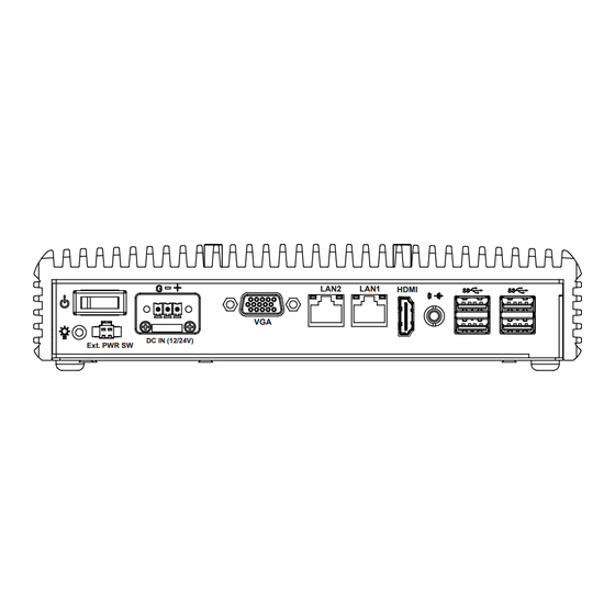
Rear I/O Ports Diagram (Normal SKU and PoE SKU) LAN1 Power DC Power Line Out Input LAN2 Button LAN2 LAN1 HDMI 4 x USB 3.0 Power LED DC IN (12/24V) Ext. PWR SW Extended HDMI Power Switch BS-E097 SERIES USER MANUAL Page: 3-2... -
Page 29: Jumper & Connector Quick Reference Table
Mini PCI Express Slot M_PCIE1 mSATA Connector M_SATA1 LVDS Connector LVDS1 Front Panel Connector JFP1 HD Audio Connector AUDIO1 Panel Inverter Connector JINV1 SATA 3.0 Connector SATA1 SATA Power Connector SATA_PWR1 BIOS Reset Connector BS-E097 SERIES USER MANUAL Page: 3-3... -
Page 30: Component Locations Of System Main Board
Make sure both the system and peripheral devices are turned OFF as sudden surge of power could damage sensitive components. Make sure BS-E097 is properly grounded. CAUTION: Observe precautions while handling electrostatic sensitive components. Make sure to ground yourself to prevent static charge while you are working on the connectors and jumpers. -
Page 31: Jumper Setting And Connector Location Of System Main
(default) COM4 JI2C1 COM3 Pin9 RI/5V/12V JLPC1 JMCU1 COM3 JDIO1 COM2 (default) SATA_PWR1 M_SATA1 COM1 SO_DIMM1 JFP1 M_PCIE1 AUDIO1 Clear CMOS Data PWR2 Normal Clear CMOS (default) LVDS1 JBAT1 USB3 FAN1 JINV1 JP_VDD1 SATA1 BS-E097 SERIES USER MANUAL Page: 3-5... -
Page 32: Bottom View Of System Main Board
Chapter 3 System Configuration 3.3.3 Bottom View of System Main Board BS-E097 SERIES USER MANUAL Page: 3-6... -
Page 33: How To Set Jumpers
PIN1 & PIN2 to create one setting by shorting. You can either connect PIN2 & PIN3 to create another setting. The same jumper diagrams are applied all through this manual. The figure below shows what the manual diagrams look and what they represent. BS-E097 SERIES USER MANUAL Page: 3-7... - Page 34 Chapter 3 System Configuration Jumper Diagrams Jumper Settings 2 pin Jumper close(enabled) Looks like this 3 pin Jumper 2-3 pin close(enabled) Looks like this Jumper Block 1-2 pin close(enabled) Looks like this BS-E097 SERIES USER MANUAL Page: 3-8...
-
Page 35: Setting Connectors And Jumpers
3.5.1 COM3 and COM4 PIN9 Definition Selection Guide Jumper Name: JP_COM3, JP_COM4 Description: COM3 and COM4 Port pin9 RI/5V/12V Selection SELECTION JUMPER SETTING JUMPER ILLUSTRATION (Default Setting) JP_COM3 JP_COM4 +12V JP_COM3 JP_COM4 JP_COM4 JP_COM3 BS-E097 SERIES USER MANUAL Page: 3-9... -
Page 36: Com Port
COM2_RX COM2_TX COM2_DTR COM2_DSR COM2_RTS COM2_CTS COM2_RI Notes: COM2 is selectable as RS-232, RS422, RS485 under BIOS setting. Default setting is RS-232. Please see Chapter 5 “Advanced – Onboard Device Configuration” for selection details. BS-E097 SERIES USER MANUAL Page: 3-10... - Page 37 RI, please see “COM3 and COM4 PIN9 Definition Selection Guide” for selection details. (optional) DIO Connector Pin Assignment: Side B PIN ASSIGNMENT DIN0 DIN1 DIN2 DIO (option) DIN3 DOUT0 DOUT1 DOUT2 DOUT3 BS-E097 SERIES USER MANUAL Page: 3-11...
-
Page 38: Dc In 3-Pin Terminal Block
DC Power Input (+12V or 16~24V) DC In (12/24V) 3.5.4 VGA Port Port Name: VGA (external connector) Description: VGA Port, D-Sub 15-pin (I/O port) PIN ASSIGNMENT PIN ASSIGNMENT PIN ASSIGNMENT CRT_RED CRT_GREEN CRT_DATA CRT_BLUE CRT_HSYNC CRT_VCC CRT_VSYNC CRT_CLK BS-E097 SERIES USER MANUAL Page: 3-12... -
Page 39: Hdmi Port
Chapter 3 System Configuration 3.5.5 HDMI Port Port Name: HDMI (external connector) Description: HDMI Port Connector ASSIGNMENT ASSIGNMENT CLK+ CLK- I2C_CLK I2C_DATA HDMI HOT_PLUG_DET BS-E097 SERIES USER MANUAL Page: 3-13... -
Page 40: Lan Port
Status Description Yellow Blink LAN Message Active Right Side LED No LAN Message Active Green 10/100Mbps LAN connection is enabled. Left Side LED Orange Giga LAN connection is enabled. No LAN switch/hub is connected BS-E097 SERIES USER MANUAL Page: 3-14... -
Page 41: Dual Usb 3.0 Port
Port Name: USB (external connector on rear I/O panel) Description: Dual USB 3.0 ports (left side) PIN ASSIGNMENT PIN ASSIGNMENT USB3_RXN4 USB3_RXP4 USB2_P4_DP USB3_TXN4 USB2_P4_DN USB3_TXP4 VCC5_USB2 USB3_RXN3 USB3_RXP3 USB3.0 USB2_P3_DP USB3_TXN3 USB2_P3_DN (left side) USB3_TXP3 VCC5_USB2 BS-E097 SERIES USER MANUAL Page: 3-15... -
Page 42: Usb 2.0 Port
GPI/GPO 7 JDIO1 Notes: Users can set the GPI/GPO configuration via Protech’s API/Utility. Default setting is GPI every time when system AC power is re-applied from power failure state Configuration can still be kept even in S5 state unless system AC power is lost. -
Page 43: I2C Wafer
Description: I2C Wafer (no use for this system) PIN ASSIGNMENT VCC5 I2C0_SCL_33 I2C0_SDA_33 JI2C1 3.5.12 MCU FW Rewrite Connector Port Name: JMCU1 Description: MCU FW Rewrite Connector for engineering use only PIN ASSIGNMENT MCU_5VSB JMCU1 MCU_SPD MCU_SPC BS-E097 SERIES USER MANUAL Page: 3-17... -
Page 44: System Fan Connector
SYSFANIN SYSFANOUT FAN1 3.5.14 DC Power Input Connector Port Name: PWR2 Description: DC Power Input Connector PIN ASSIGNMENT PIN ASSIGNMENT VCC12 VCC12 PWR2 Note: The voltage of input power should be 12V or 16~24V. BS-E097 SERIES USER MANUAL Page: 3-18... -
Page 45: Mini Pci Express Slot
Mini PCI Express is the successor of the Mini PCI card and provides an increased data throughput. The cards have a detached network interface and are equipped with one lane. They are used in particular in embedded designs or compact box PCs. BS-E097 SERIES USER MANUAL Page: 3-19... -
Page 46: Msata Connector
Chapter 3 System Configuration 3.5.16 mSATA Connector Port Name: M_SATA1 Description: mSATA Slot (An USB type mPCIe card is supported.) ASSIGNMENT ASSIGNMENT V3P3S_MSATA SATA_RXP1 V3P3S_MSATA SATA_RXN1 SATA_TXN1 M_SATA1 SATA_TXP1 USB2_P0_DN USB2_P0_DP V3P3S_MSATA V3P3S_MSATA V3P3S_MSATA BS-E097 SERIES USER MANUAL Page: 3-20... -
Page 47: Lvds Connector
Description: LVDS Connector (no use for this system) LVDS1 ASSIGNMENT ASSIGNMENT LVDS_VCC LVDS_CLKB_DP LVDS_CLKB_DN LVDS_B2_DN LVDS_B2_DP LVDS_B1_DP LVDS_B1_DN LVDS_B3_DN LVDS_B3_DP LVDS_B0_DN LVDS_B0_DP LVDS_CLKA_DP LVDS_CLKA_DN LVDS_A2_DN LVDS_A2_DP LVDS_A1_DP LVDS_A1_DN LVDS_A0_DN LVDS_A0_DP LVDS_A3_DN LVDS_A3_DP LVDS_VCC LVDS_VCC BS-E097 SERIES USER MANUAL Page: 3-21... -
Page 48: Slide Switch For Lvds Resolution Selection
Description: Slide Switch for LVDS Resolution/Channel/Color Bit Selection (no use for this system) SELECTION SETTING 800 x 600 1CH/18bit (Default Setting) 1024 x 768 1CH/18bit 1024 x 768 1CH/24bit 1280 x 768 1CH/18bit 1280 x 800 1CH/18bit BS-E097 SERIES USER MANUAL Page: 3-22... - Page 49 Chapter 3 System Configuration SELECTION SETTING 1280 x 960 1CH/18bit 1280 x 1024 2CH/24bit 1366 x 768 1CH/18bit 1366 x 768 1CH/24bit 1440 x 900 2CH/24bit 1400 x 1050 2CH/24bit BS-E097 SERIES USER MANUAL Page: 3-23...
- Page 50 Chapter 3 System Configuration SELECTION SETTING 1600 x 900 2CH/24bit 1680 x 1050 2CH/24bit 1600 x 1200 2CH/24bit 1920 x 1080 2CH/24bit 1920 x 1200 2CH/24bit BS-E097 SERIES USER MANUAL Page: 3-24...
-
Page 51: Front Panel Connector
POWER BTN 3.5.20 HD Audio Connector Port Name: AUDIO1 Description: HD Audio Connector for Line In / Line Out / Mic In. ASSIGNMENT ASSIGNMENT LINE-OUT-L LINE-OUT-L HD_GND HD_GND HD_LINE-IN-R HD_LINE-IN-L HD_GND HD_GND HD_MIC1-R HD_MIC1-L AUDIO1 BS-E097 SERIES USER MANUAL Page: 3-25... -
Page 52: Panel Inverter Connector
LVDS_BKLTEN 3.5.22 SATA 3.0 Connector Port Name: SATA1 Description: Serial ATA 3.0 Connector ASSIGNMENT SATA_TXP0 SATA_TXN0 SATA1 SATA_RXN0 SATA_RXP0 3.5.23 SATA Power Connector Port Name: SATA1_PWR1 Description: Serial ATA Power Connector ASSIGNMENT VCC5 SATA_PWR1 BS-E097 SERIES USER MANUAL Page: 3-26... -
Page 53: Bios Reset Connector
3.5.24 BIOS Reset Connector Jumper Name: JP9 Description: BIOS Reset Connector This connector is only for Protech's engineers. (Purpose: BIOS reset). Please do not use this connector; otherwise, the system might be crashed. 3.5.25 LVDS Backlight Control Selection Jumper Name: JP7 Description: Jumper for selecting PIN4 (LVDS_BKLCTL) voltage of JINV1. -
Page 54: Lvds Vcc Voltage Selection
LVDS VCC Voltage Selection Jumper Name: JP_VDD1 Description: Voltage selection jumper for selecting PIN1, PIN29, PIN30 (LVDS_VCC) voltage of LVDS1. (no use for this system) SELECTION JUMPTER SETTING JUMPER ILLUSTRATION 3.3V (Default Setting) JP_VDD1 JP_VDD1 BS-E097 SERIES USER MANUAL Page: 3-28... -
Page 55: Clear Cmos Data Selection
JUMPER ILLUSTRATION Open Normal (Default Setting) Clear CMOS* 3.5.28 RTC Battery Power Input Connector Port Name: JBAT1 Description: It must connector to a RTC battery for a normal RTC function. ASSIGNMENT VBAT (+3.0~3.3V) JBAT1 BS-E097 SERIES USER MANUAL Page: 3-29... -
Page 56: Software Utilities
Chipset Software Installation Utility • Installing Graphics Driver Utility • Installing LAN Driver Utility • Installing Sound Driver Utility ® • Installing Intel Serial I/O Driver Utility • Microsoft Hotfix KB3211320 and KB3213986 Driver Installation BS-E097 SERIES USER MANUAL Page: 4-1... - Page 57 Chapter 4 Software Utilities Introduction Enclosed with the BS-E097 Series package is our driver utilities contained in a DVD-ROM disk. Refer to the following table for driver locations: For Windows 10 2016 64-bit OS: Filename Win10 (Assume that DVD-ROM drive...
- Page 58 Note: Install the driver utilities immediately after the OS installation is completed. It is strongly recommended that you follow the WARNING: installation sequence below: (1) Chipset Driver (2) Hotfix (3) Graphics Driver (4) TXE Driver (5) Other Drivers BS-E097 SERIES USER MANUAL Page: 4-3...
-
Page 59: Introduction
The utility pack is to be installed only for Windows 10 64bit, and it should be installed immediately after the OS installation is finished. Please follow the steps below: Connect the USB DVD-ROM device to BS-E097 and insert the driver disk. Enter WIN 10-2016 Chipset or WIN 10-2019 Chipset folder where the Chipset driver is located Click Setup.exe file for driver installation. -
Page 60: Installing Intel ® Trusted Execution Engine Installation Utility
Trusted Execution Engine Installation Utility To install the utility, simply follow the steps below: Connect the USB DVD-ROM device to BS-E097 and insert the driver disk. Select Windows 10 2016 or Windows 10 2019 OS platform. Enter the TXE folder where the driver is located. -
Page 61: Installing Graphics Driver Utility
Chapter 4 Software Utilities Installing Graphics Driver Utility The GRAPHICS interface embedded in BS-E097 can support a wide range of display types. To install the Graphics driver utility, follow the steps below: Connect the USB DVD-ROM device to BS-E097 and insert the driver disk. -
Page 62: Installing Lan Driver Utility
Enhanced with LAN function, BS-E097 supports various network adapters. To install the LAN Driver, follow the steps below: Connect the USB DVD-ROM device to BS-E097 and insert the driver disk. Select Windows 10 2016 or Windows 10 2019 OS platform. -
Page 63: Installing Sound Driver Utility
Windows 10 64bit. To install the Sound Driver, follow the steps below: Connect the USB DVD-ROM device to BS-E097 and insert the driver disk. Select Windows 10 2016 or Windows 10 2019 OS platform. Open the Sound folder where the driver is located. -
Page 64: Installing Intel ® Serial I/O Driver Utility
Installing Intel Serial I/O Driver Utility To install the Serial I/O Driver, follow the steps below: Connect the USB DVD-ROM device to BS-E097 and insert the driver disk. Select the Windows 10 2016/2019 OS platform. Open the SerialIO folder where the driver is located. -
Page 65: Microsoft Hotfix Kb3211320 And Kb3213986 Driver Installation
Run windows10.0-kb3211320-x64 and windows10.0-kb3213986-x64 with administrative privileges. Follow the on-screen instructions to complete the installation. Once the installation is completed, shut down the system and restart BS-E097 for the changes to take effect. BS-E097 SERIES USER MANUAL Page: 4-10... -
Page 66: Bios Setup
Setup information is retained when the system is powered off. The BIOS Setup Utilities consist of the following menu items: Main Menu • Advanced Menu • Chipset Menu • Security Menu • Boot Menu • Save & Exit Menu • BS-E097 SERIES USER MANUAL Page: 5-1... -
Page 67: Introduction
EFI BIOS provides an user interface that allows you to modify hardware configuration, e.g. change the system date and time, enable/disable a system component, determine bootable device priority, set up personal password, etc., which is convenient for engineers to perform modifications and customize the computer BS-E097 SERIES USER MANUAL Page: 5-2... - Page 68 3. The system configuration is reset after the user configures to clear CMOS data via the JP4 jumper. 4. The power of the CMOS RAM became lost and the system configuration has been erased. All the menu settings are described in details in this chapter. BS-E097 SERIES USER MANUAL Page: 5-3...
-
Page 69: Accessing Setup Utility
POST message will be displayed: Figure 5-2. POST Screen with AMI Logo Press <Del> or <Esc> to access the Setup Utility program and the Main menu of the Aptio Setup Utility will appear on the screen as below: BS-E097 SERIES USER MANUAL Page: 5-4... - Page 70 Load the previous configuration values. <F3> Load the default configuration values. <F4> Save the current values and exit the BIOS setup menu. <Esc> Close the sub-menu. Trigger the confirmation to exit BIOS setup menu. BS-E097 SERIES USER MANUAL Page: 5-5...
-
Page 71: Main
Access Level No changeable options Displays the current user access level. Enables/Disables Built-in Display (LVDS). - Disabled It is recommended user disables Built-in Built-in Display - Enabled (default) Display function for the system without LVDS. BS-E097 SERIES USER MANUAL Page: 5-6... - Page 72 The “Day” is automatically changed. System Time Hour, minute, second Sets the system time. The format is [Hour: Minute: Second]. Users can directly enter values or use <+> or <-> arrow keys to increase/decrease it. BS-E097 SERIES USER MANUAL Page: 5-7...
-
Page 73: Advanced
S5 RTC Wake Settings Sub-Menu RTC wake parameters. CPU Configuration Sub-Menu CPU configuration parameters. F81964 Super IO Configuration Sub-Menu System Super IO chip parameters USB Configuration Sub-Menu USB configuration parameters. Platform Trust Technology Sub-Menu Platform Trust Technology. BS-E097 SERIES USER MANUAL Page: 5-8... -
Page 74: Advanced - Acpi Settings
Hibernate (OS/S4 Sleep State). This option (S4) - Enabled (default) may be not effective with some OS. - Disabled Enables or Disables System ability to Sleep Enable Sleep (S3) - Enabled (default) (OS/S3 Sleep State). BS-E097 SERIES USER MANUAL Page: 5-9... -
Page 75: Advanced - Onboard Device Configuration
5.4.2 Advanced – Onboard Device Configuration Menu Path Advanced > Onboard Device Configuration Onboard Device Configuration Screen BIOS Setting Options Description/Purpose - RS-422 COM2 Mode Selection - RS-232 (default) Selects COM2 mode. - RS-485 BS-E097 SERIES USER MANUAL Page: 5-10... -
Page 76: Advanced - Hardware Monitor
Detects and displays the voltage level VCC3V No changeable options of VCC3V in supply. VSB3V No changeable options Detects and displays VSB3V voltage. Detects and displays the voltage level VCC5V No changeable options of VCC5V in supply. BS-E097 SERIES USER MANUAL Page: 5-11... - Page 77 The rule is as follows: -Manual Duty Mode System Fan Smart Fan • < 40°C: 40% -Auto Duty-Cycle Mode Control • 40~50°C: 40~50% (default) • 50~60°C: 50~70% • 60~65°C: 70~100% • > 65°C: 100% BS-E097 SERIES USER MANUAL Page: 5-12...
- Page 78 Options Description/Purpose Manual Duty Mode - 0% User can select expected duty cycle - 30% (PWM fan type). - 40% - 50% - 60% - 70% - 80% - 90% - Full Speed (default) BS-E097 SERIES USER MANUAL Page: 5-13...
-
Page 79: Advanced - F81964 Watchdog
Description/Purpose - Disabled (default) Enables/Disables 81964 Watchdog Enable Watchdog - Enabled timer settings. Multiple options Selects count of watchdog timer. Watchdog Timer Count ranging from 10 to 255 Watchdog Timer = 1sec * Count BS-E097 SERIES USER MANUAL Page: 5-14... -
Page 80: Advanced - S5 Rtc Wake Settings
• Fixed Time: The system will wake Wake system from S5 - Fixed Time on the time (hr::min::sec) specified. - Dynamic Time • Dynamic Time: The system will wake on the current time + increased minute(s). BS-E097 SERIES USER MANUAL Page: 5-15... -
Page 81: S5 Rtc Wake Settings [Fixed Time]
Multiple options ranging Sets a minute for schedule power on Wake up minute from 0 to 59 event. Multiple options ranging Sets a second for schedule power on Wake up second from 0 to 59 event. BS-E097 SERIES USER MANUAL Page: 5-16... -
Page 82: S5 Rtc Wake Settings [Dynamic Time]
S5 RTC Wake Setting Screen (Dynamic Time) BIOS Setting Options Description/Purpose Sets a period of time (in minutes) to Multiple options Wake up minute increase wake up the system after it enters S5 ranging from 1 to 5 state. BS-E097 SERIES USER MANUAL Page: 5-17... -
Page 83: Advanced - Cpu Configuration
CPU power management options. When enabled, a VMM can utilize Intel Virtualization - Disabled the additional hardware capabilities Technology - Enabled (default) provided by Vanderpool Technology. - Disabled (default) VT-d Enables/Disables CPU VT-d. - Enabled BS-E097 SERIES USER MANUAL Page: 5-18... -
Page 84: Cpu Configuration - Socket 0 Cpu Information
L1 Data Cache No changeable options L1 Data Cache Size. L1 Code Cache No changeable options L1 Code Cache Size. L2 Cache No changeable options L2 Cache Size. L3 Cache No changeable options L3 Cache Size. BS-E097 SERIES USER MANUAL Page: 5-19... -
Page 85: Cpu Configuration - Cpu Power Management
Menu Path Advanced > CPU Configuration > CPU Power Management Configuration CPU Power Management Configuration Screen BIOS Setting Options Description/Purpose Enables/Disables Intel SpeedStep - Disabled EIST feature for dynamic scaling processor - Enabled (default) frequency. BS-E097 SERIES USER MANUAL Page: 5-20... -
Page 86: Advanced - F81964 Super Io Configuration
Displays the super I/O chip model. Serial Port 1 Configuration Sub-Menu COM1 parameters. Serial Port 2 Configuration Sub-Menu COM2 parameters. Serial Port 3 Configuration Sub-Menu COM3 parameters. Serial Port 4 Configuration Sub-Menu COM4 parameters. BS-E097 SERIES USER MANUAL Page: 5-21... -
Page 87: F81964 Super Io Configuration - Serial Port
- IO=3F8h; IRQ=4 Allows users to change Device's - IO=3F8h; IRQ=3,4,5,7,9,10,11,12; Resource settings. New settings Change Settings - IO=2F8h; IRQ=3,4,5,7,9,10,11,12; will be reflected on this Setup Page - IO=3E8h; IRQ=3,4,5,7,9,10,11,12; after System restarts. - IO=2E8h; IRQ=3,4,5,7,9,10,11,12; BS-E097 SERIES USER MANUAL Page: 5-22... -
Page 88: Configuration
- IO=2F8h; IRQ=3 Allows users to change Device's - IO=3F8h; IRQ=3,4,5,7,9,10,11,12; Resource settings. New settings will Change Settings - IO=2F8h; IRQ=3,4,5,7,9,10,11,12; be reflected on this Setup Page after - IO=3E8h; IRQ=3,4,5,7,9,10,11,12; System restarts. - IO=2E8h; IRQ=3,4,5,7,9,10,11,12; BS-E097 SERIES USER MANUAL Page: 5-23... -
Page 89: Configuration
- IO=3E8h; IRQ=7 Allows users to change Device's - IO=3E8h; IRQ=3,4,5,7,9,10,11,12; Resource settings. New settings will Change Settings - IO=2E8h; IRQ=3,4,5,7,9,10,11,12; be reflected on this Setup Page after - IO=2F0h; IRQ=3,4,5,7,9,10,11,12; System restarts. - IO=2E0h; IRQ=3,4,5,7,9,10,11,12; BS-E097 SERIES USER MANUAL Page: 5-24... -
Page 90: F81964 Super Io Configuration - Serial Port 4 Configuration
- IO=2E8h; IRQ=10 Allows users to change Device's - IO=3E8h; IRQ=3,4,5,7,9,10,11,12; Resource settings. New settings Change Settings - IO=2E8h; IRQ=3,4,5,7,9,10,11,12; will be reflected on this Setup Page - IO=2F0h; IRQ=3,4,5,7,9,10,11,12; after System restarts. - IO=2E0h; IRQ=3,4,5,7,9,10,11,12 BS-E097 SERIES USER MANUAL Page: 5-25... -
Page 91: Advanced - Usb Configuration
Optical drives MASS STORAGE - Forced FDD are emulated as 'CD-ROM'. Drives DEVICES: [drive(s)] - Hard Disk with no media will be emulated - CD-ROM according to a drive type. BS-E097 SERIES USER MANUAL Page: 5-26... -
Page 92: Advanced - Platform Trust Technology
The Platform Trust Technology allows users to configure advanced TPM settings such as fTPM. Platform Trust Technology Screen BIOS Setting Options Description/Purpose Enables or Disables fTPM. - Disabled fTPM It must be disabled when discrete TPM - Enabled (default) is used. BS-E097 SERIES USER MANUAL Page: 5-27... -
Page 93: Chipset
This menu allows users to configure advanced Chipset settings such as North Bridge and South Bridge configuration parameters. Chipset Screen BIOS Setting Options Description/Purpose North Bridge Sub-Menu North Bridge Parameters. South Bridge Sub-Menu South Bridge Parameters. BS-E097 SERIES USER MANUAL Page: 5-28... -
Page 94: Chipset - North Bridge
"8192 MB (LPDDR3)". Memory Speed No changeable options Displays memory speed. Displays the current amount and Memory Slot0 No changeable options type of memory on each memory slot, e.g. "8192 MB (LPDDR3)". BS-E097 SERIES USER MANUAL Page: 5-29... -
Page 95: Chipset - South Bridge
Description/Purpose HD-Audio Configuration Sub-Menu HD-Audio configuration settings. LPSS Configuration Sub-Menu LPSS configuration settings. PCI Express Configuration Sub-Menu PCI Express configuration settings. SATA Drives Sub-Menu SATA Drives configuration settings. Miscellaneous Configuration Sub-Menu Miscellaneous configuration settings BS-E097 SERIES USER MANUAL Page: 5-30... -
Page 96: South Bridge - Hd-Audio Configuration
Chapter 5 BIOS Setup 5.5.2.1 South Bridge - HD-Audio Configuration Menu Path Chipset > South Bridge > HD-Audio Configuration HD-Audio Configuration Screen BIOS Setting Options Description/Purpose - Disable HD-Audio Support Enables/Disables HD-Audio support. - Enable (default) BS-E097 SERIES USER MANUAL Page: 5-31... -
Page 97: South Bridge - Lpss Configuration
Enables/Disables LPSS I2C #1 (D22:F0) - Enable (default) support. - Standard Mode - Fast Mode (default) Set LPSS I2C #1 Speed Selects LPSS I2C #1 speed. - Fast Plus Mode - High Speed Mode BS-E097 SERIES USER MANUAL Page: 5-32... -
Page 98: South Bridge - Pci Express Configuration
Sub-Menu PCIE RP1 parameters (I210 LAN). (I210 LAN) PCI E Express Root Port 2 Sub-Menu PCIE RP2 parameters (I210 LAN). (I210 LAN) PCI E Express Root Port 3 Sub-Menu PCIE RP3 parameters (Mini-PCIe). (Mini-PCIe) BS-E097 SERIES USER MANUAL Page: 5-33... - Page 99 Description/Purpose - Disable PCI Express Root Port 1 Enables/Disables PCIE root port 1 - Enable (I210 LAN) (I210 LAN). - Auto (default) - Auto (default) PCIe Speed - Gen1 Configures PCIe speed. - Gen2 BS-E097 SERIES USER MANUAL Page: 5-34...
- Page 100 Description/Purpose - Disable PCI Express Root Port 2 Enables/Disables PCIE root port 2 - Enable (I210 LAN) (I210 LAN). - Auto (default) - Auto (default) PCIe Speed - Gen1 Configures PCIe speed. - Gen2 BS-E097 SERIES USER MANUAL Page: 5-35...
- Page 101 BIOS Setting Options Description/Purpose - Disable PCI Express Root Port 3 Enables/Disables PCIE root port 3 - Enable (Mini-PCIe) (Mini-PCIe). - Auto (default) - Auto (default) PCIe Speed - Gen1 Configures PCIe speed. - Gen2 BS-E097 SERIES USER MANUAL Page: 5-36...
-
Page 102: South Bridge - Sata Drives
Enables/Disables SATA port 0. - Enabled (default) Displays SATA drive branding SATA Port 1 No changeable options information if device exists on port 1. - Disabled Port 1 Enables/Disables SATA port 1. - Enabled (default) BS-E097 SERIES USER MANUAL Page: 5-37... -
Page 103: South Bridge - Miscellaneous Configuration
Win 8/8.1/10 don't support WOL from - Disable Wake On Lan hybrid shutdown state (S4). If you want to - Enable (default) support WOL from classic shutdown state (S5), please turn off 'fast startup' feature in BS-E097 SERIES USER MANUAL Page: 5-38... -
Page 104: Security
Setup utility than a user. Heed that a user password does not provide access to most of the features in the Setup utility. Security Screen BIOS Setting Options Description/Purpose Password can be 3-20 Specifies the administrator Administrator Password alphanumeric characters. password. BS-E097 SERIES USER MANUAL Page: 5-39... - Page 105 <Enter>, and the password dialog entry box appears. Select the configured Administrator Password or User Password that you want to delete. Leave the dialog box blank and press <Enter>. Press <Enter> again when the password confirmation box appears. BS-E097 SERIES USER MANUAL Page: 5-40...
-
Page 106: Boot
• On: Enables the NumLock - On (default) function automatically after the Bootup NumLock State - Off system is powered on. • Off: Disables the NumLock function after the system is powered on. BS-E097 SERIES USER MANUAL Page: 5-41... - Page 107 - Disabled (default) Enables or Disables Fast Boot Fast Boot - Enabled Options. -Windows (default) OS Selection -Android Select the target OS. -Intel Linux - [Drive(s)] Boot Option #1~#n Sets the system boot order. - Disabled BS-E097 SERIES USER MANUAL Page: 5-42...
-
Page 108: Save & Exit
Discard Changes and Reset to discard any changes you have made and restore the factory BIOS defaults. Load User Defaults You may simply press F3 at any time to load the Optimized Values which resets all BIOS settings to the factory defaults. Save & Exit Screen BS-E097 SERIES USER MANUAL Page: 5-43... - Page 109 Save the changes done so far as User Save as User Defaults No changeable options Defaults. Restore the User Defaults to all the Restore User Defaults No changeable options setup options. Forces to boot from selected Boot Override - [Drive(s)] [drive(s)]. BS-E097 SERIES USER MANUAL Page: 5-44...
-
Page 110: Appendix A System Diagrams
Appendix A System Diagrams This appendix provides exploded diagrams and part numbers of BS-E097 system. The following topics are included: BS-E097 System Exploded Diagrams (Normal SKU and • PoE SKU) BS-E097 SATA HDD Exploded Diagram • BS-E097 Heatsink Exploded Diagram •... -
Page 111: Bs-E097 System Exploded Diagram (Normal Sku
Appendix A System Diagrams BS-E097 System Exploded Diagram (Normal SKU) 09 15 BS-E097 SERIES USER MANUAL Page: A-2... - Page 112 Appendix A System Diagrams Description Part No. Q’ty BS-E097 Heatsink Case (Black) See Page A-6 BS-E097 Front Case for Normal C 20-101-03068416 (w/Paint) (Black) BS-E097 Back Case for VGA (w/Paint) 20-101-03067416 (Black) BS-E097 BOT Case (w/Paint)(Black) 20-101-03061416 BS-E097 HDD Assy Flat Plate Holder...
-
Page 113: Bs-E097 System Exploded Diagram (Poe Sku
Appendix A System Diagrams BS-E097 System Exploded Diagram (PoE SKU) BS-E097 SERIES USER MANUAL Page: A-4... - Page 114 Appendix A System Diagrams Description Part No. Q’ty BS-E097 Heatsink Case (Black) See Page A-6 20-101-03066416 BS-E097 Back Case for VGA (w/Paint) 20-101-03067416 (Black) BS-E097 BOT Case (w/Paint)(Black) 20-101-03061416 BS-E097 HDD Assy Flat Plate Holder See Page A-7 BE-0986RA-E3N / E4N BE-0986 Rubber Foot (Φ11.1x3.96mm) (Black)
-
Page 115: Bs-E097 Heatsink Exploded Diagram
Appendix A System Diagrams BS-E097 Heatsink Exploded Diagram Description Part No. Q’ty BS-E097 Heatsink Case (Black) 81-002-11841007 (217.5x140.6x46mm) BS-E097 CPU CU Block (110x18x2mm) 81-002-21018002 Flat Head Screw #1 / M2x0.4Px5mm 22-215-20005011 BS-E097 SERIES USER MANUAL Page: A-6... -
Page 116: Bs-E097 Sata Hdd Exploded Diagram
Appendix A System Diagrams BS-E097 SATA HDD Exploded Diagram Description Part No. Q’ty BS-E097 HDD Plate Holder Kit 20-229-03001416 Flat Head Screw #2 / M3x0.5Px5mm 22-215-30005011 2.5” SATA HDD BS-E098 SATA HDD & Power Cable 27-008-39503081 L=150mm BS-E097 SERIES USER MANUAL... -
Page 117: Din-Rail Side Bracket Kit Installation Exploded Diagram
03 2X Description Part No. Q’ty Flat Head Screw #2 / M4x0.7Px6mm 22-215-40006011 (Black) BR-0986 Din Rail Side Bracket 20-106-02061419 (w/Paint) (Black) DIN Rail Clip (USA 10) 52-901-00002417 Flat Head Screw #2 / T3.0x8mm 22-112-30008311 BS-E097 SERIES USER MANUAL Page: A-8... -
Page 118: Bs-E097 Wall Mount Exploded Diagram
Appendix A System Diagrams BS-E097 Wall Mount Exploded Diagram Description Part No. Q’ty BS-E098 Stand (w/Paint) (Black) (NCT) 20-017-02062405 Flat Head Screw M4x0.7Px6mm (Black) 22-215-40006011 BS-E097 SERIES USER MANUAL Page: A-9... -
Page 119: Appendix B Technical Summary
Appendix B Technical Summary This appendix will give you a brief introduction of the allocation maps for BS-E097 resources. The following topics are included: • Interrupt Map • I/O Map • Memory Map • Configuring WatchDog Timer • Flash BIOS Update... -
Page 120: Interrupt Map
IRQ 70 Microsoft ACPI-Compliant System IRQ 71 Microsoft ACPI-Compliant System IRQ 72 Microsoft ACPI-Compliant System IRQ 73 Microsoft ACPI-Compliant System IRQ 74 Microsoft ACPI-Compliant System IRQ 75 Microsoft ACPI-Compliant System IRQ 76 Microsoft ACPI-Compliant System BS-E097 SERIES USER MANUAL Page: B-2... - Page 121 IRQ 103 Microsoft ACPI-Compliant System IRQ 104 Microsoft ACPI-Compliant System IRQ 105 Microsoft ACPI-Compliant System IRQ 106 Microsoft ACPI-Compliant System IRQ 107 Microsoft ACPI-Compliant System IRQ 108 Microsoft ACPI-Compliant System IRQ 109 Microsoft ACPI-Compliant System BS-E097 SERIES USER MANUAL Page: B-3...
- Page 122 IRQ 136 Microsoft ACPI-Compliant System IRQ 137 Microsoft ACPI-Compliant System IRQ 138 Microsoft ACPI-Compliant System IRQ 139 Microsoft ACPI-Compliant System IRQ 140 Microsoft ACPI-Compliant System IRQ 141 Microsoft ACPI-Compliant System IRQ 142 Microsoft ACPI-Compliant System BS-E097 SERIES USER MANUAL Page: B-4...
- Page 123 IRQ 169 Microsoft ACPI-Compliant System IRQ 170 Microsoft ACPI-Compliant System IRQ 171 Microsoft ACPI-Compliant System IRQ 172 Microsoft ACPI-Compliant System IRQ 173 Microsoft ACPI-Compliant System IRQ 174 Microsoft ACPI-Compliant System IRQ 175 Microsoft ACPI-Compliant System BS-E097 SERIES USER MANUAL Page: B-5...
- Page 124 IRQ 202 Microsoft ACPI-Compliant System IRQ 203 Microsoft ACPI-Compliant System IRQ 204 Microsoft ACPI-Compliant System IRQ 256 Microsoft ACPI-Compliant System IRQ 257 Microsoft ACPI-Compliant System IRQ 258 Microsoft ACPI-Compliant System IRQ 259 Microsoft ACPI-Compliant System BS-E097 SERIES USER MANUAL Page: B-6...
- Page 125 IRQ 286 Microsoft ACPI-Compliant System IRQ 287 Microsoft ACPI-Compliant System IRQ 288 Microsoft ACPI-Compliant System IRQ 289 Microsoft ACPI-Compliant System IRQ 290 Microsoft ACPI-Compliant System IRQ 291 Microsoft ACPI-Compliant System IRQ 292 Microsoft ACPI-Compliant System BS-E097 SERIES USER MANUAL Page: B-7...
- Page 126 IRQ 319 Microsoft ACPI-Compliant System IRQ 320 Microsoft ACPI-Compliant System IRQ 321 Microsoft ACPI-Compliant System IRQ 322 Microsoft ACPI-Compliant System IRQ 323 Microsoft ACPI-Compliant System IRQ 324 Microsoft ACPI-Compliant System IRQ 325 Microsoft ACPI-Compliant System BS-E097 SERIES USER MANUAL Page: B-8...
- Page 127 IRQ 352 Microsoft ACPI-Compliant System IRQ 353 Microsoft ACPI-Compliant System IRQ 354 Microsoft ACPI-Compliant System IRQ 355 Microsoft ACPI-Compliant System IRQ 356 Microsoft ACPI-Compliant System IRQ 357 Microsoft ACPI-Compliant System IRQ 358 Microsoft ACPI-Compliant System BS-E097 SERIES USER MANUAL Page: B-9...
- Page 128 IRQ 385 Microsoft ACPI-Compliant System IRQ 386 Microsoft ACPI-Compliant System IRQ 387 Microsoft ACPI-Compliant System IRQ 388 Microsoft ACPI-Compliant System IRQ 389 Microsoft ACPI-Compliant System IRQ 390 Microsoft ACPI-Compliant System IRQ 391 Microsoft ACPI-Compliant System BS-E097 SERIES USER MANUAL Page: B-10...
- Page 129 IRQ 418 Microsoft ACPI-Compliant System IRQ 419 Microsoft ACPI-Compliant System IRQ 420 Microsoft ACPI-Compliant System IRQ 421 Microsoft ACPI-Compliant System IRQ 422 Microsoft ACPI-Compliant System IRQ 423 Microsoft ACPI-Compliant System IRQ 424 Microsoft ACPI-Compliant System BS-E097 SERIES USER MANUAL Page: B-11...
- Page 130 IRQ 451 Microsoft ACPI-Compliant System IRQ 452 Microsoft ACPI-Compliant System IRQ 453 Microsoft ACPI-Compliant System IRQ 454 Microsoft ACPI-Compliant System IRQ 455 Microsoft ACPI-Compliant System IRQ 456 Microsoft ACPI-Compliant System IRQ 457 Microsoft ACPI-Compliant System BS-E097 SERIES USER MANUAL Page: B-12...
- Page 131 IRQ 484 Microsoft ACPI-Compliant System IRQ 485 Microsoft ACPI-Compliant System IRQ 486 Microsoft ACPI-Compliant System IRQ 487 Microsoft ACPI-Compliant System IRQ 488 Microsoft ACPI-Compliant System IRQ 489 Microsoft ACPI-Compliant System IRQ 490 Microsoft ACPI-Compliant System BS-E097 SERIES USER MANUAL Page: B-13...
- Page 132 IRQ 4294967284 Intel(R) I210 Gigabit Network Connection IRQ 4294967285 Intel(R) I210 Gigabit Network Connection IRQ 4294967286 Intel(R) I210 Gigabit Network Connection IRQ 4294967287 Intel(R) I210 Gigabit Network Connection IRQ 4294967288 Intel(R) I210 Gigabit Network Connection BS-E097 SERIES USER MANUAL Page: B-14...
- Page 133 IRQ 4294967293 Root Port - 5AD9 Intel(R) Celeron(R)/Pentium(R) Processor PCI Express IRQ 4294967294 Root Port - 5AD8 Note: This resource information was gathered using Windows 10 (the IRQ could be assigned differently depending on OS). BS-E097 SERIES USER MANUAL Page: B-15...
-
Page 134: I/O Map
Motherboard resources 0x00000070-0x00000070 System CMOS/real time clock 0x00000078-0x00000CF7 PCI Express Root Complex 0x00000080-0x0000008F Motherboard resources 0x00000092-0x00000092 Motherboard resources 0x000000A0-0x000000A1 Programmable interrupt controller 0x000000A4-0x000000A5 Programmable interrupt controller 0x000000A8-0x000000A9 Programmable interrupt controller 0x000000AC-0x000000AD Programmable interrupt controller BS-E097 SERIES USER MANUAL Page: B-16... - Page 135 PCI Express Root Port - 5AD9 Intel(R) Celeron(R)/Pentium(R) Processor 0x0000E000-0x0000EFFF PCI Express Root Port - 5AD8 Intel(R) HD Graphics 0x0000F000-0x0000F03F Intel(R) Celeron(R)/Pentium(R) Processor 0x0000F040-0x0000F05F SMBUS - 5AD4 Standard SATA AHCI Controller 0x0000F060-0x0000F07F 0x0000F080-0x0000F083 Standard SATA AHCI Controller BS-E097 SERIES USER MANUAL Page: B-17...
-
Page 136: Memory Map
PCI Express Root Port - 5AD9 Intel(R) I210 Gigabit Network 0x91280000-0x912FFFFF Connection #2 Intel(R) I210 Gigabit Network 0x9127C000-0x9127FFFF Connection #2 Intel(R) I210 Gigabit Network 0x91180000-0x911FFFFF Connection Intel(R) I210 Gigabit Network 0x9117C000-0x9117FFFF Connection High precision event timer 0xFED00000-0xFED003FF BS-E097 SERIES USER MANUAL Page: B-18... - Page 137 Intel(R) Trusted Execution Engine 0x9131D000-0x9131DFFF Interface 0x80000000-0x8FFFFFFF Intel(R) HD Graphics 0x91314000-0x91315FFF Standard SATA AHCI Controller 0x9131A000-0x9131A0FF Standard SATA AHCI Controller 0x91319000-0x913197FF Standard SATA AHCI Controller 0x7B800001-0x7BFFFFFF PCI Express Root Complex 0x7C000001-0x7FFFFFFF PCI Express Root Complex BS-E097 SERIES USER MANUAL Page: B-19...
-
Page 138: Configuring Watchdog Timer
To exit the Extended Function Mode, writing 0xAA to the EFER is required. Once the chip exits the Extended Function Mode, it is in the normal running mode and is ready to enter the configuration mode. BS-E097 SERIES USER MANUAL Page: B-20... - Page 139 ; ------------------------- ------------------------------- ; ------------------ Select Logical Device 7 of watchdog timer ------------ ;-------------------------- Enable Watch dog feature -------------------------- ; ---------- Set timeout interval as 30seconds and start counting ---------- ;------------------------------ Enable Watch PME------------------------------- BS-E097 SERIES USER MANUAL Page: B-21...
- Page 140 Appendix B Technical Summary ;------------------------- Set second as counting unit -------------------------- ;--------------------------- Start the watchdog timer --------------------------- ;----------------------Exit the extended function mode ----------------------- BS-E097 SERIES USER MANUAL Page: B-22...
-
Page 141: Flash Bios Update
(3) The system will go into the BIOS setup menu. (4) Select [Boot] menu. (5) Set the USB bootable device as the 1st boot device. (6) Press F4 to save the configuration and exit the BIOS setup menu. BS-E097 SERIES USER MANUAL Page: B-23... - Page 142 BIOS ROM may be crashed and the system will be unable to boot up next time. After the BIOS update procedure is completed, the following messages will display: BS-E097 SERIES USER MANUAL Page: B-24...
- Page 143 Restart the system and boot up with the new BIOS configurations. The BIOS Update is completed after the system is restarted. Reboot the system and verify if the BIOS version shown on the initialization screen has been updated. BS-E097 SERIES USER MANUAL Page: B-25...
Need help?
Do you have a question about the BS-E097 and is the answer not in the manual?
Questions and answers