
Subscribe to Our Youtube Channel
Related Manuals for protech MH-5102 Series


Summary of Contents for protech MH-5102 Series
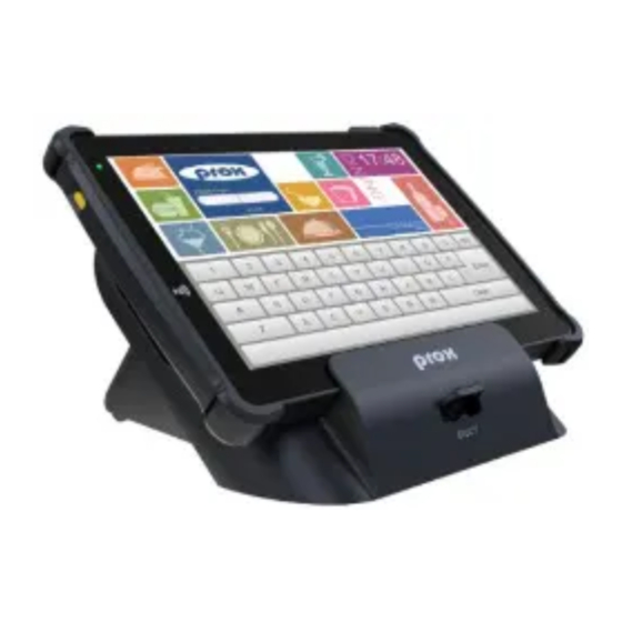
- Page 1 USER MANUAL MH-5102 10.1” Integrated Pad Powered By Intel ® Atom ® Processor MH-5102 M1...
- Page 2 MH-5102 10.1” Integrated Pad Powered By ® ® Intel Atom Processor COPYRIGHT NOTICE & TRADEMARK All trademarks and registered trademarks mentioned herein are the property of their respective owners. This manual is copyrighted in Mar. 2019. You may not reproduce or transmit in any form or by any means, electronic, or mechanical, including photocopying and recording.
- Page 3 FCC NOTICE This equipment has been tested and found to comply with the limits for a Class A digital device, pursuant to part 15 of the FCC Rules. These limits are designed to provide reasonable protection against harmful interference when the equipment is operated in a co mmercial environment.
-
Page 4: Table Of Contents
Contents Introduction ..................1-1 About This Manual ..............1-2 Getting Started ..................2-1 Package List ................2-2 Pad System Overview ............... 2-3 2.2.1 Front View ................. 2-3 2.2.2 Rear View ................2-3 2.2.3 Side View ................2-4 2.2.4 Top View ................2-4 2.2.5 Bottom View .............. - Page 5 2.4.8 Scanning Barcodes and QR Codes ........ 2-15 2.4.9 Installing Hand Strap ............2-16 2.4.10 Installing Neck Strap ............2-17 Pad Specifications ..............2-18 Lite Cradle Specifications ............2-22 OS Specifications ..............2-23 Safety Precautions ..............2-24 System Configuration ................. 3-1 Pad Function Buttons and I/O Ports ..........
- Page 6 3.5.6 M.2 E_Key Connector (M2_E1) ........3-11 3.5.7 Battery Lock Switch Button (BAT_LOCK) ....... 3-12 3.5.8 Universal Serial Bus 3.0 Connector (USB1) ....3-12 3.5.9 MSR/Front Camera Connector (CCM2-MSR) ....3-13 3.5.10 Smart Card Reader Connector (SCR1)......3-14 3.5.11 Vibrator Connector (CON1) ..........3-14 3.5.12 Slide Switch Selection (SW2, SW3, SW4, SW5) ....
- Page 7 3.8.14 SIM Card Connector (SIM1) ..........3-28 Pad Daughter Board MR-5102RA-3 ........3-29 3.9.1 Top View of Pad Daughter Board MR-5102RA-3 .... 3-29 3.10 Pad Daughter Board MR-5102RA-4 ........3-30 3.10.1 Top View of Pad Daughter Board MR-5102RA-4 .... 3-30 3.11 Daughter Board MR-5100RA-5 and MR-5100RA-2 Connectors Quick Reference Table ............
- Page 8 Installing G-Sensor Software Installation Utility ......4-6 Installing Wi-Fi and Bluetooth Software Installation Utility ..4-7 4.5.1 Installing Wi-Fi Software Installation Utility ......4-7 4.5.2 Installing Bluetooth Software Installation Utility ....4-8 Installing Light Sensor Software Installation Utility ....4-9 Installing Microsoft Hotfix kb3211320 and kb3213986 Driver Utility ....................
- Page 9 Exploded Diagram For Camera Module & Barcode Scanner Module Assembly ..................A-5 Exploded Diagram For Back Cover Assembly ......A-6 Exploded Diagram For Smart Card Reader Assembly ....A-7 Lite Cradle Exploded Diagrams ..............A-8 Exploded Diagram For Cradle Top Cover Assembly .....A-8 Exploded Diagram For Cradle PCBA & Bottom Cover Assembly .....................A-10 Appendix B Technical Summary ..........
- Page 10 Revision History The revision history of MH-5102 User Manual is described below: Version No. Revision History Date 2019/3/28 Initial Release...
-
Page 11: Introduction
Introduction This chapter provides the introduction for the MH-5102 system as well as the framework of the user manual. The following topic is included: • About This Manual Page: 1-1 MH-5102 SERIES USER MANUAL... -
Page 12: About This Manual
Appendix A System Assembly Diagrams This appendix provides the exploded diagrams and part numbers of the MH-5102. Appendix B Technical Summary This appendix provides the information about the allocation maps for system resources and System BIOS update procedure. Page: 1-2 MH-5102 SERIES USER MANUAL... -
Page 13: Getting Started
• Lite Cradle System Diagrams • Quick Setup • Pad Specifications • Lite Cradle Specifications • Safety Precautions Experienced users can go to Chapter 3 System Configuration on page 3-1 for a quick start. Page: 2-1 MH-5102 SERIES USER MANUAL... -
Page 14: Package List
Item Q’ty MH-5102 Integrated Pad Quick Reference Guide AC Power Adapter for Pad Hand Strap (optional) Neck Strap (optional) Lite Cradle (optional) Power Adapter for Lite Cradle (optional) Power Cord for Lite Cradle (optional) Page: 2-2 MH-5102 SERIES USER MANUAL... -
Page 15: Pad System Overview
Chapter 2 Getting Started Pad System Overview Unit: mm 2.2.1 Front View Power LED 267.84 2.2.2 Rear View Smart Card Reader Camera Battery Pack Page: 2-3 MH-5102 SERIES USER MANUAL... -
Page 16: Side View
Chapter 2 Getting Started 2.2.3 Side View 25.2 Scan Button Scan Button Power Button USB 3.0 Port DC-IN 2.2.4 Top View Barcode Scanner Earphone Jack 17.7 2.2.5 Bottom View POGO Pins Page: 2-4 MH-5102 SERIES USER MANUAL... -
Page 17: Lite Cradle System Overview
Chapter 2 Getting Started Lite Cradle System Overview Unit: mm 2.3.1 Front View 2.3.2 Rear View COM DWR IN 12V Page: 2-5 MH-5102 SERIES USER MANUAL... -
Page 18: Side View
Chapter 2 Getting Started 2.3.3 Side View Kensington Lock Slot 217.23 2.3.4 Top View Page: 2-6 MH-5102 SERIES USER MANUAL... -
Page 19: Bottom View
Chapter 2 Getting Started 2.3.5 Bottom View LAN and Cash Drawer Selection Page: 2-7 MH-5102 SERIES USER MANUAL... -
Page 20: Quarter View
Chapter 2 Getting Started 2.3.6 Quarter View Page: 2-8 MH-5102 SERIES USER MANUAL... -
Page 21: Quick Setup
Windows. Tap Start icon from the bottom left corner of the Pad and select the displayed menu icon and select Shut down from the selection list to turn off the Pad power. Page: 2-9 MH-5102 SERIES USER MANUAL... -
Page 22: Turning The Power On And Connect To Local Network From
(Refer to the Side View section of Pad for the location of Power Button.) Refer to the I/O Ports Diagram section of Lite Cradle for the location of LAN port. Page: 2-10 MH-5102 SERIES USER MANUAL... -
Page 23: Installing Battery For Pad
Note 1: The factory default battery cycle life guarantees to retain 80 percent of its original capacity after the battery has been charged and discharged for 300 times. Note 2: Batteries are consumerables and the limited warranty for MH-5102 battery is 1 year only. MH-5102 SERIES USER MANUAL Page: 2-11... -
Page 24: Recharging Battery From Pad
Step 2. Plug the other end to an AC power outlet. The Power LED indicator on the top left corner of the touchscreen will then flash GREEN. After the battery is fully charged, the Power LED indicator will turn to a solid green. Page: 2-12 MH-5102 SERIES USER MANUAL... -
Page 25: Installing Integrated Pad Onto Lite Cradle
Lite Cradle base respectively. Step 2. Lock the two locking tabs of Pad into their mating slots inside the Lite Cradle base and the Pad snaps into place. Step 3. The installation is completed. Page: 2-13 MH-5102 SERIES USER MANUAL... -
Page 26: Separating Integrated Pad From Lite Cradle
Step 1. Push down the Lock Switch on the front of Lite Cradle. Step 2. Separate the integrated pad from the lite cradle. See the picture below: Push down the Lock Switch to eject. Page: 2-14 MH-5102 SERIES USER MANUAL... -
Page 27: Scanning Barcodes And Qr Codes
(Refer to the Top View section of Pad for the location of the Barcode Scanner.) After the barcode/QR code has been scanned successfully, you will hear one beep sound. Page: 2-15 MH-5102 SERIES USER MANUAL... -
Page 28: Installing Hand Strap
Note: The strap bracket set is pre-installed for easy user installation before the shipment. The strap bracket set includes 2 x strap brackets, 2 x pan head screws (M3 x 6 mm) and 1 x Velcro badge. Page: 2-16 MH-5102 SERIES USER MANUAL... -
Page 29: Installing Neck Strap
Step 3. Put the installed neck strap around your neck to carry the Pad around. Note: You can also select to put the neck strap through the lower openings of the right-side and left-side bumper rubbers. Page: 2-17 MH-5102 SERIES USER MANUAL... -
Page 30: Pad Specifications
Speaker Type 1 x 1W Speaker, 1 x Audio Jack (headset microphone) Wi-Fi + Type 802.11 ac/a/b/g/n 2T2R wireless LAN and Bluetooth Bluetooth 4.1 M.2 module Module IC Interface Wi-Fi: SDIO / Bluetooth: UART Page: 2-18 MH-5102 SERIES USER MANUAL... - Page 31 Main battery(1S2P) 8 hours @ 7900mAh Operation time Sub Battery RTC Battery 160mAh Battery Pack Main battery Power ON: 5 hours Charging time Power OFF: 4 hours IP Rating Body unit IP54 (front panel only) Drop Impact 1.2m Resistance Page: 2-19 MH-5102 SERIES USER MANUAL...
- Page 32 USB (Co-layout with 3G module) External I/O Ports DC-IN Jack Type 1 x DC-IN Jack Cradle Type 1 x POGO pins (1x10 pins) Connector Type 1 x Standard USB 3.0 (Type A) for external expansion Page: 2-20 MH-5102 SERIES USER MANUAL...
- Page 33 For 4G LTE network services Audio Jack Type 1 x Audio Jack (3.5mm) External Buttons (for side I/O & front panel) Power Button Type 1 x Power Button Scan Button Type 2 x Scan buttons (left & right) Page: 2-21 MH-5102 SERIES USER MANUAL...
-
Page 34: Lite Cradle Specifications
L x W x T 220 x 217.23 x 131.65mm Weight Lite Cradle only About 858g Note: The functions of Ethernet LAN & Cash Drawer are co-layout and can be selected by DIP Switch. Page: 2-22 MH-5102 SERIES USER MANUAL... -
Page 35: Os Specifications
Chapter 2 Getting Started OS Specifications Description ® Windows 10 IoT Enterprise LTSB 2016 Supports 64 bits ® Windows Pro 10 Supports 64 bits Page: 2-23 MH-5102 SERIES USER MANUAL... -
Page 36: Safety Precautions
If heavy stains are present, moisten a cloth with diluted neutral washing agent or alcohol and then wipe thoroughly with a dry cloth. • If dust is accumulated on the case surface, remove it by using a s pecial vacuum cleaner for computers. Page: 2-24 MH-5102 SERIES USER MANUAL... -
Page 37: System Configuration
• Setting Pad Main Board Connectors • Setting Daughter Board MR-5102RA-1 Connectors for Carrier Board • Daughter Board MR-5100RA-5 and MR-5100RA-2 Connectors Quick Reference Table • Setting Daughter Board MR-5100RA-5 Connectors and Jumpers • Setting Daughter Board MR-5100RA-2 Connectors Page: 3-1 MH-5102 SERIES USER MANUAL... -
Page 38: Pad Function Buttons And I/O Ports
ASSIGNMENT ASSIGNMENT DC-IN +12V +12V 3.1.3 USB Port Port Name: USB1 Description: USB Type A Port (Side I/O) ASSIGNMENT USB1 +5V (Max. current: 0.5A) Note: The USB1 port is provided with Standby power 5V. Page: 3-2 MH-5102 SERIES USER MANUAL... -
Page 39: Audio Port
LEFT RIGHT HP_DET Lite Cradle I/O Ports Diagram 3.2.1 I/O Ports Diagram The I/O ports are located on the bottom side of the Lite Cradle. DC-IN RJ-45 Cash D-Sub 9 USB 2.0 Drawer Switch Page: 3-3 MH-5102 SERIES USER MANUAL... -
Page 40: Pad Main Board Component Locations
CAUTION: Observe precautions while handling electrostatic sensitive components. Make sure to ground yourself to prevent static charge while configuring the connectors. Use a grounding wrist strap and place all electronic components in any static-shielded devices. Page: 3-4 MH-5102 SERIES USER MANUAL... -
Page 41: Bottom View Of Pad Main Board Component Locations
Chapter 3 System Configuration 3.3.2 Bottom View of Pad Main Board Component Locations M2_E1 BAT_LOCK CCM2-MSR J_MIPI_CON SCR1 CN_BARCODE CON1 SW3 SW2 Figure 3-2 MB-5102 Main Board Component Locations (Bottom View) Page: 3-5 MH-5102 SERIES USER MANUAL... -
Page 42: Pad Main Board Connectors Quick Reference Table
M.2 E_Key Connector M2_E1 Barcode Scanner Connector CN_BARCODE Battery Lock Switch Connector BAT_LOCK MSR/Front Camera Connector CCM2-MSR Smart Card Reader Connector SCR1 Slide Switch Description Location Slide Switch Selection SW2, SW3, SW4, SW5 Board ID Switch Page: 3-6 MH-5102 SERIES USER MANUAL... -
Page 43: Setting Pad Main Board Connectors And Slide Switches
Chapter 3 System Configuration Setting Pad Main Board Connectors and Slide Switches 3.5.1 MIPI Connector (J_MIPI_CON) Connector Location: J_MIPI_CON (rear side of main board) Description: MIPI Connector ASSIGNMENT LEDA+ LEDA+ J_MIPI_CON LEDA- LEDA- ID_1 DIMO CLKP CLKN Page: 3-7 MH-5102 SERIES USER MANUAL... -
Page 44: Earphone Jack Connector (Cn_Jack1)
Chapter 3 System Configuration ASSIGNMENT ID_2 V3P3S_MIPI V3P3S_MIPI 3.5.2 Earphone Jack Connector (CN_JACK1) Connector Location: CN_JACK1 (top side of main board) Description: Earphone Jack Connector ASSIGNMENT PIN ASSIGNMENT RIGHT LEFT HP_DET CN_JACK1 Page: 3-8 MH-5102 SERIES USER MANUAL... -
Page 45: Barcode Scanner Connector (Cn_Barcode)
Description: Barcode Scanner Connector ASSIGNMENT V3P3S/V5P0S CN_BARCODE Power Down Buzzer Wake up Trigger 3.5.4 Right Barcode Switch Button (BUTTON2) Connector Location: BUTTON2 (top side of main board) Description: Right Barcode Switch Button ASSIGNMENT SCAN_EN_SW BUTTON2 Page: 3-9 MH-5102 SERIES USER MANUAL... -
Page 46: Power Switch Button (Button4)
Chapter 3 System Configuration 3.5.5 Power Switch Button (BUTTON4) Connector Location: BUTTON4 (top side of main board) Description: Power Switch Button ASSIGNMENT PWRBTN_N BUTTON4 Page: 3-10 MH-5102 SERIES USER MANUAL... -
Page 47: E_Key Connector (M2_E1)
M.2 E_Key Connector signals: ASSIGNMENT ASSIGNMENT V3P3A_WIFI V3P3A_WIFI SDMMC2_CLK SDMMC2_CMD SDMMC2_DAT0 SDMMC2_DAT1 SDMMC2_DAT2 SDMMC2_DAT3 BT_HOST_WAKE_R SDIO_WAKE UART1_RXD WLAN_ON_N UART1_TXD M2_E1/ UART1_CTS PCIE_TXP0 UART1_RTS PCIE_TXN0 PCIE_RXP0 PCIE_RXN0 PCIE_REFCLK0_P PCIE_REFCLK0_N WIFI_SUSCLK WLAN_ON_N_R PCIE_CLKREQ0_M.2_R DISABLE PCIE_WAKEJ W_DISABLE V3P3A_WIFI V3P3A_WIFI Page: 3-11 MH-5102 SERIES USER MANUAL... -
Page 48: Universal Serial Bus 3.0 Connector (Usb1)
ASSIGNMENT PIN ASSIGNMENT BAT_LOCK BAT_LOCK 3.5.8 Universal Serial Bus 3.0 Connector (USB1) Connector Location: USB1 (top side of main board) Description: USB 3.0 Connector ASSIGNMENT PIN ASSIGNMENT USB3.0_RXDN USB2.0_DN USB3.0_RXDP USB2.0_DP USB1 USB3.0_TXDN USB3.0_TXDP Page: 3-12 MH-5102 SERIES USER MANUAL... -
Page 49: Msr/Front Camera Connector (Ccm2-Msr)
Chapter 3 System Configuration 3.5.9 MSR/Front Camera Connector (CCM2-MSR) Connector Location: CCM2-MSR (rear side of main board) Description: MSR/Front Camera Connector ASSIGNMENT CCM1_DN CCM1_DP CCM2-MSR Page: 3-13 MH-5102 SERIES USER MANUAL... -
Page 50: Smart Card Reader Connector (Scr1)
Connector Location: SCR1 (rear side of main board) Description: Smart Card Reader Connector ASSIGNMENT Buck-Boost_VIN Buck-Boost_VIN Buck-Boost_VIN SW2/SW3 SLP_SOIX_3P3_N SCR1 3.5.11 Vibrator Connector (CON1) Connector Location: CON1 (rear side of main board) Description: Vibrator Connector ASSIGNMENT V3P3A_VB CON1 Page: 3-14 MH-5102 SERIES USER MANUAL... -
Page 51: Slide Switch Selection (Sw2, Sw3, Sw4, Sw5)
SW2 / SW3 / SW4 / SW5 3.5.13 Board ID Switch (SW1) Switch Location: SW1 (rear side of main board) Description: Board ID Switch For MB-5102RA-11N BOM, Board ID: 0000 For MB-5102RA-12N BOM, Board ID: 0001 Page: 3-15 MH-5102 SERIES USER MANUAL... - Page 52 Chapter 3 System Configuration For MB-5102RA-13N BOM, Board ID: 0011 For MB-5102RA-14N BOM, Board ID: 0100 For MB-5102RA-15N BOM, Board ID: 0010 For MB-5102RA-16N BOM, Board ID: 0101 Page: 3-16 MH-5102 SERIES USER MANUAL...
-
Page 53: Pad Daughter Board Reference Table: Mr-5102Ra-1
Battery Connector BAT1 MCU Firmware Update Connector Micro SD Card Connector CCD Front Webcam Connector CCM1 SIM Card Connector SIM1 Top Side Left Barcode Switch Button BUTTON1 DC IN Jack Connector DC_IN1 Cradle Connector CRADLE1 Page: 3-17 MH-5102 SERIES USER MANUAL... -
Page 54: Pad Daughter Board Mr-5102Ra-1 Connector Locations
CAUTION: Observe precautions while handling electrostatic sensitive components. Make sure to ground yourself to prevent static charge while configuring the connectors. Use a grounding wrist strap and place all electronic components in any static-shielded devices. Page: 3-18 MH-5102 SERIES USER MANUAL... -
Page 55: Bottom View Of Pad Daughter Board Mr-5102Ra-1
Bottom View of Pad Daughter Board MR-5102RA-1 Component Locations CCM1 SPK1 NFC1 BAT1 C1 C2 C3 C4 SIM1 M/N: M_PCIE1 C5 C6 C7 SCR_DCN BAT2 S/N: TOUCH1 Figure 3-4 MR-5102RA-1 Daughter Board Component Locations (Bottom View) Page: 3-19 MH-5102 SERIES USER MANUAL... -
Page 56: Setting Pad Daughter Board Mr-5102Ra-1 Connectors
Connector Location: TOUCH1 (rear side of daughter board MR-5102RA-1) Description: Touchscreen Connector ASSIGNMENT +V3P3_V1P8_TCH I2C5_Touch_SCL I2C5_Touch_SDA TOUCH1 TOUCH_INT_N TOUCH_RESET_N 3.8.2 Left Barcode Switch Button (BUTTON1) Connector Location: BUTTON1 (top side of daughter board MR-5102RA-1) Description: Left Barcode Switch Button ASSIGNMENT SCAN_EN_SW BUTTON1 Page: 3-20 MH-5102 SERIES USER MANUAL... -
Page 57: Nfc Connector (Nfc1)
NFC_DOWNLOAD V3P3S_NFC +V1P8SX 3.8.4 MR-5102RA-1 Power Supply Connector from Main Board (SCR_DCN) Connector Location: SCR_DCN (rear side of daughter board MR-5102RA-1) Description: MR-5102RA-1 Power Supply Connector from Main Board ASSIGNMENT DCIN DCIN DCIN SCR_DCN Page: 3-21 MH-5102 SERIES USER MANUAL... -
Page 58: Rtc Battery Connector (Bat2)
Chapter 3 System Configuration 3.8.5 RTC Battery Connector (BAT2) Connector Location: BAT2 (rear side of daughter board MR-5102RA-1) Description: RTC Battery Connector ASSIGNMENT BAT2 Page: 3-22 MH-5102 SERIES USER MANUAL... -
Page 59: Speaker Connector (Spk1)
Connector Location: SPK1 (rear side of daughter board MR-5102RA-1-BOT) Description: Speaker Connector PIN ASSIGNMENT LEFT_SPK RIGHT_SPK SPK1 3.8.7 Battery Connector (BAT1) Connector Location: BAT1 (rear side of daughter board MR-5102RA-1) Description: Battery Connector ASSIGNMENT BATT_SENSE BAT1 BAT_SCL BAT_SDA Page: 3-23 MH-5102 SERIES USER MANUAL... -
Page 60: Dc In Jack Connector (Dc_In1)
Chapter 3 System Configuration 3.8.8 DC IN Jack Connector (DC_IN1) Connector Location: DC_IN1 (top side of daughter board MR-5102RA-1) Description: DC IN Jack Connector ASSIGNMENT PIN ASSIGNMENT DCIN DCIN DC_IN1 Page: 3-24 MH-5102 SERIES USER MANUAL... -
Page 61: Mini Pci Express Slot (M_Pcie1)
Description: Mini-PCI Express Slot ASSIGNMENT ASSIGNMENT PCIE_WAKEJ V3P3A V1P5S_MINI M_CLKREQJ SIM1_PWR SIM1_DATA M_PCIE_CLKN SIM1_CLK M_PCIE_CLKP SIM1_RESET SIM1_VPP SIM1_SW2 SIM1_SW1 PMU_PLTRST_N PCIE_P2_RXN V3_3A PCIE_P2_RXP V1P5S_MINI SMB_3P3_SCL M_PCIE1 PCIE_P2_TXN SMB_3P3_SDA PCIE_P2_TXP USB2_P7_DN USB2_P7_DP V3P3A V3P3A VCC1_5 V3P3A Page: 3-25 MH-5102 SERIES USER MANUAL... -
Page 62: Cradle Connector (Cradle1)
CRA_DCIN CRADLE1 CRA_DCIN USB_DP USB_DP USB_DN USB_DN V5P0S 3.8.11 MCU Firmware Update Connector (JP5) Connector Location: JP5 (rear side of daughter board MR-5102RA-1) Description: MCU Firmware Update Connector ASSIGNMENT MCU_MISO MCU_ADC MCU_SCK MCU_MOSI MCU_RST Page: 3-26 MH-5102 SERIES USER MANUAL... -
Page 63: Microsd Card Connector (J2)
Chapter 3 System Configuration 3.8.12 MicroSD Card Connector (J2) Connector Location: J2 (rear side of daughter board MR-5102RA-1) Description: MicroSD Card Connector ASSIGNMENT SDMMC3_DAT2 SDMMC3_DAT3 SDMMC3_CMD +V3P3S_SD_SW SDMMC3_CLK SDMMC3_DAT0 SDMMC3_DAT1 SDMMC_CD_N Page: 3-27 MH-5102 SERIES USER MANUAL... -
Page 64: Rear Camera Connector (Ccm1)
V5P0 CCM1 3.8.14 SIM Card Connector (SIM1) Connector Location: SIM1 (rear side of daughter board MR-5102RA-1) Description: SIM Card Connector ASSIGNMENT PIN ASSIGNMENT VSIM C1 C2 C3 C4 DATA C5 C6 C7 C8 SIM1 Page: 3-28 MH-5102 SERIES USER MANUAL... -
Page 65: Pad Daughter Board Mr-5102Ra-3
Pad Daughter Board MR-5102RA-3 3.9.1 Top View of Pad Daughter Board MR-5102RA-3 The daughter board MR-5102RA-3 is served as board to board for CPU to carrier board connection. Figure 3-5 MR-5102RA-3 Daughter Board (Top View) Page: 3-29 MH-5102 SERIES USER MANUAL... -
Page 66: Pad Daughter Board Mr-5102Ra-4
Top View of Pad Daughter Board MR-5102RA-4 The daughter board MR-5102RA-4 is served as the Transfer board for Wi-Fi / Bluetooth SiP module connected to M.2 form factor. Figure 3-6 MR-5102RA-4 Daughter Board (Top View) Page: 3-30 MH-5102 SERIES USER MANUAL... -
Page 67: Daughter Board Mr-5100Ra-5 And Mr-5100Ra-2 Connectors
Universal Serial Bus 2.0 Connector USB1 (Dual Layers) Cash Drawer Connector DRW1 Local Area Network Connector LAN1 DC IN Jack Connector DC_IN1 LAN Port & Cash Drawer Function Switch (MR-5100RA-5 Bottom Side) Lite Cradle Connector CRADLE1 (MR-5100RA-2) Page: 3-31 MH-5102 SERIES USER MANUAL... -
Page 68: Jumper Settings Of Daughter Board Mr-5100Ra-5
Pad system are actually COM1 and COM2 ports of the daughter board respectively, because the Lite Cradle’s COM ports are deployed according to OS Image built by Protech and COM1 port placement has been used by Pad system. -
Page 69: Daughter Board Mr-5100Ra-2 Connector Locations
Figure 3-7 MR-5100RA-5 Daughter Board Component Locations (Bottom View) 3.11.2 Daughter Board MR-5100RA-2 Connector Locations CRADLE1 Figure 3-8 MR-5100RA-2 Daughter Board Component Locations (Top View) Pb-free Figure 3-9 MR-5100RA-2 Daughter Board Component Locations (Bottom View) Page: 3-33 MH-5102 SERIES USER MANUAL... -
Page 70: Com1, Com2 Port Pin9 Definition Selection Guide
Connectors and Jumpers 3.12.1 COM1, COM2 Port Pin9 Definition Selection Guide Jumper Location: JP_COM1 and JP_COM2 Description: COM1, COM2 Port Pin9 RI/+5V/+12V Selection SELECTION JUMPER SETTING JUMPER ILLUSTRATION (Default Setting) JP_COM1 JP_COM2 JP_COM1 JP_COM2 JP_COM1 JP_COM2 Page: 3-34 MH-5102 SERIES USER MANUAL... -
Page 71: Com Port (Com1)
ASSIGNMENT COM2 RI/5V/12V COM2 Pin 9 is selectable for RI, +5V or +12V by jumper setting. Default setting is RI. Note: Please see “COM1, COM2 Port Pin9 Definition Selection Guide” section for details selection Page: 3-35 MH-5102 SERIES USER MANUAL... -
Page 72: Dual Usb Ports (Usb1)
Port Name: USB1 Description: Dual USB 2.0 Type A Connectors ASSIGNMENT ASSIGNMENT VCC5V VCC5V USB_DN USB_DN USB_DP USB_DP USB1 Note: The top USB 2.0 connector pin assignments are the same as the one below. Page: 3-36 MH-5102 SERIES USER MANUAL... -
Page 73: Local Area Network (Lan) Port (Lan1)
Ethernet connection. LAN LED Color Status Description Indicator Left Side Orange Blink Giga LAN connection is activated. 10/100Mbps LAN connection is Green Blink activated. Right Side Green LAN switch/hub connected. Page: 3-37 MH-5102 SERIES USER MANUAL... -
Page 74: Cash Drawer Port (Drw1)
LAN Port & Cash Drawer Function Switch (SW1) Connector Name: SW1 Description: LAN Port and Cash Drawer function selection ASSIGNMENT CASH DRAWER Note: Users need to use a ball point pen or a pin to toggle the DIP switch. Default: LAN Page: 3-38 MH-5102 SERIES USER MANUAL... -
Page 75: Lite Cradle Connector (Cradle1)
Chapter 3 System Configuration 3.13 Setting Daughter Board MR-5100RA-2 Connector 3.13.1 Lite Cradle Connector (CRADLE1) Connector Name: CRADLE1 Description: Lite Cradle Connector CRADLE1 ASSIGNMENT CRA_DCIN CRA_DCIN USB_DP USB_DP USB_DN USB_DN V5P0S Page: 3-39 MH-5102 SERIES USER MANUAL... -
Page 76: Software Utilities
• Installing G-Sensor Software Installation Utility • Installing Wi-Fi & Bluetooth Software Installation Utility • Installing Light Sensor Software Installation Utility • Installing Microsoft Hotfix kb3211320 and kb3213986 Driver Utility • Cash Drawer API Reference MH-5102 SERIES USER MANUAL Page: 4-1... -
Page 77: Introduction
Microsoft Hotfix kb3211320 and kb3213986 Platform\6_Hot for Windows10 64-bit critical security Fix\Win10-64Bit update : Support Note: After the OS installation is completed, the driver utilities will also be installed at the same time. MH-5102 SERIES USER MANUAL Page: 4-2... -
Page 78: Installing Intel Chipset Software Installation Utility
Chip > Win10-64Bit > cht-t4_win10_x64_ww08_th2_d0_pr2\Installer\SEC Installer folder. Click SetupTXE.exe file for driver installation. Follow the on-screen instructions to install the driver. Once the installation is completed, restart MH-5102 for the changes to take effect. MH-5102 SERIES USER MANUAL Page: 4-3... - Page 79 • Sensor driver utility • TXEI driver utility • UART driver utility • WCE driver utility • For more details on the installation procedure, refer to the MH-5102 README V1.0.pdf file located under C:\MH-5102_v1.0. MH-5102 SERIES USER MANUAL Page: 4-4...
-
Page 80: Installing Audio Realtek Software Installation Utility
Click the file "rtii2sac.inf" and then right-click the mouse and select “install” from the drop-down list. Once the installation is completed, restart MH-5102 for the changes to take effect, and the audio function can start to work normally. MH-5102 SERIES USER MANUAL Page: 4-5... -
Page 81: Installing G-Sensor Software Installation Utility
Please follow the steps below to install G-Sensor driver utilities: Enter the C:\MH-5102_v1.0 >DRIVER > Platform\3_G-sensor\Win10-64Bit\4.22.0080_signed folder. Click setup.exe file for driver installation. Once the installation is completed, restart MH-5102 for the changes to take effect. MH-5102 SERIES USER MANUAL Page: 4-6... -
Page 82: Installing Wi-Fi And Bluetooth Software Installation Utility
Click the file "bcmwdidhdpcie.inf" and then right-click the mouse and select “install” from the drop-down list. Follow the on-screen instructions to install the Wi-Fi driver. Once the installation is completed, restart MH-5102 for the changes to take effect. MH-5102 SERIES USER MANUAL Page: 4-7... -
Page 83: Installing Bluetooth Software Installation Utility
Click the file "BtwSerialBus.inf " and then right-click the mouse and select “install” from the drop-down list. Follow the on-screen instructions to install the Bluetooth driver. Once the installation is completed, restart MH-5102 for the changes to take effect. MH-5102 SERIES USER MANUAL Page: 4-8... -
Page 84: Installing Light Sensor Software Installation Utility
Click the file "ALS_Combo.inf " and then right-click the mouse and select “install” from the drop-down list. Once the installation is completed, restart MH-5102 for the changes to take effect, and the audio function can start to work normally. MH-5102 SERIES USER MANUAL Page: 4-9... -
Page 85: Installing Microsoft Hotfix Kb3211320 And Kb3213986 Driver Utility
Click the windows10.0-kb3211320-x64 and windows10.0-kb3213986-x64 files for critical security update. Follow the on-screen instructions to complete the installation. Once the installation is completed, shut down the system and restart MH-5102 for the changes to take effect. MH-5102 SERIES USER MANUAL Page: 4-10... -
Page 86: Cash Drawer Api Function
True (1) on success, False (0) on failure Example if (Init_Drawer() > 0) { //"Success!" } else { //"Failure!" Release_Drawer int Release_Drawer(void); Purpose Release the Cash Drawer. Return True (1) on success, False (0) on failure MH-5102 SERIES USER MANUAL Page: 4-11... - Page 87 = 1 (Open the Cash Drawer2) time:Parameter range is 5~50, unit is 10 millisecond. (Time range: 50~500 millisecond) Return True (1) on success, False (0) on failure Example if (Drawer_Open(1, 10) == 0) { //"Failure!" } else { //"Success!" MH-5102 SERIES USER MANUAL Page: 4-12...
- Page 88 0x31 -> Drawer is open ; 0x30 -> Drawer is close ; 0x00 -> Failure Example Drawer_ST = Drawer_Status(); if (Drawer_ST == 0x31) { //"Open!" } else if (Drawer_ST == 0x30) { //"Close!" } else { //"Failure!" MH-5102 SERIES USER MANUAL Page: 4-13...
-
Page 89: Bios Setup
NVRAM so that the Setup information is retained when the system is powered off. The BIOS Setup Utilities consist of the following menu items: Main Menu • Advanced Menu • Security Menu • Boot Menu • Exit Menu • MH-5102 SERIES USER MANUAL Page: 5-1... -
Page 90: Introduction
MH-5102 SERIES USER MANUAL Page: 5-2... -
Page 91: Accessing Setup Utility
All the menu settings are described in details in this chapter. Accessing Setup Utility After the system is powered on, BIOS will enter the Power-On Self-Test (POST) routines and the POST message will be displayed: Figure 5-2. POST Screen MH-5102 SERIES USER MANUAL Page: 5-3... - Page 92 Chapter 5 BIOS Setup Figure 5-3. Front Page Screen MH-5102 SERIES USER MANUAL Page: 5-4...
- Page 93 English. You may use <↑> or <↓> key to select among the items and press <Enter> to confirm and enter the sub-menu. The following table provides the list of the navigation keys that you can use while operating the BIOS setup menu. MH-5102 SERIES USER MANUAL Page: 5-5...
-
Page 94: Main
No changeable options Displays the eMMC total size. MCU Version No changeable options Displays the MCU version. System Memory No changeable options Displays Memory Speed. Speed Cache RAM No changeable options Displays Cache RAM size. MH-5102 SERIES USER MANUAL Page: 5-6... - Page 95 No changeable options Displays the PMC FW Patch version. TXE FW Version No changeable options Displays TXE FW Version. No changeable options Displays the GOP version. Microcode No changeable options Displays the Microcode FW version. Revision MH-5102 SERIES USER MANUAL Page: 5-7...
- Page 96 System Time - hour Specifies the current time. - minute - Second System Date - month Specifies the current date. - day - year About this Displays this Software information. No changeable options Software MH-5102 SERIES USER MANUAL Page: 5-8...
-
Page 97: Advanced
Chapter 5 BIOS Setup Advanced Menu Path Advanced This menu provides security configurations and chipset configuration. Advanced Menu Screen Advanced BIOS Setting Options Description/Purpose Security Configuration Sub-Menu Security Configuration. Advanced Chipset Configuration Chipset Configuration Sub-Menu Options. MH-5102 SERIES USER MANUAL Page: 5-9... -
Page 98: Advanced - Security Configuration
- Enabled TXE Firmware Update TXE Firmware Update. - Disabled - Enabled TXE EOP Message TXE EOP Message. - Disabled TXE Unconfiguration - YES Sends EOP Message before you Perform - No enter OS. MH-5102 SERIES USER MANUAL Page: 5-10... -
Page 99: Advanced - Chipset Configuration
Advanced > Chipset Configuration BIOS Setting Options Description/Purpose To control the NFC function - Enabled NFC Switch - Disabled on the O.S. To control camera function on - Enabled Camera Switch the O.S. - Disabled MH-5102 SERIES USER MANUAL Page: 5-11... -
Page 100: Advanced - Chipset Configuration - Usb Configuration
USB ports (0 ~ 9). USB Port #0 - Enabled Disables USB port #0. - Disabled USB Port #1 Disables USB port #1. - Enabled - Disabled USB Port #2 - Enabled Disables USB port #2. - Disabled MH-5102 SERIES USER MANUAL Page: 5-12... -
Page 101: Security
Options Description/Purpose Current TPM Device TPM State No changeable options Displays the TPM state. Supervisor Password No changeable options Displays the Supervisor Password state. User Password No changeable options Displays the User Password state. MH-5102 SERIES USER MANUAL Page: 5-13... -
Page 102: Boot
- Enabled Enables or Disables booting in Text Quiet Boot - Disabled Mode. Network Stack - Enabled Network Stack supports Windows 8 - Disabled BitLocker Unlock / UEFI IPv4/IPv6 PXE/ Legacy PXE OPROM. MH-5102 SERIES USER MANUAL Page: 5-14... - Page 103 - Acpi 5.0 - Enabled Disables or Enables booting to USB Boot - Disabled USB boot devices. The number of seconds that the Timeout - second firmware will wait before booting the original default boot selection. MH-5102 SERIES USER MANUAL Page: 5-15...
-
Page 104: Exit
No changeable options BIOS settings. Load Custom Defaults No changeable options Loads Custom Defaults. Save Custom Defaults No changeable options Saves Custom Defaults. Cancels the BIOS settings you have Discard Changes No changeable options previously configured. MH-5102 SERIES USER MANUAL Page: 5-16... -
Page 105: Appendix A System Diagrams
Exploded Diagram for Back Cover Assembly • Exploded Diagram for Smart Card Reader Assembly • Exploded Diagrams for Lite Cradle Exploded Diagram for Cradle Top Cover Assembly • Exploded Diagram for Cradle PCBA & Bottom Cover • Assembly MH-5102 SERIES USER MANUAL Page: A-1... - Page 106 LCD Panel (OCA direct bonding) 52-380-14401831 MH-5102 Top Cover 30-002-12210455 MH-5100 Bumper Right 30-013-48300378 MH-5100 Bumper Left 30-013-48200378 MH-5100 Barcode Button 30-046-28110378 MH-5100 Power Button 30-002-28310378 MH-5100 Barcode Lens (Black) 30-021-02230378 Vibration Motor 27-055-35501071 MH-5102 SERIES USER MANUAL Page: A-2...
- Page 107 Round Head With Spring Washer Screw 22-235-25006011 (M2.5x0.45Px6mm) MH-5102 Carrier PCBA MH-5102 CPU PCBA MH-5102 Board to Board PCBA Round Head With Spring Washer Screw #1 22-232-20005311 / M2x0.4Px5mm Sub-Battery Thermal Pad 15x15mm Thermal Pad 10x10mm 81-006-81010003 Page: A-3 MH-5102 SERIES USER MANUAL...
- Page 108 Round Washer Head Screw #1/T2.0x5mm 22-132-20005011 MH-5100 MSR Bumper Rubber MSR Module 52-551-02043910 PA-8225 MSR Plate Pin 20-005-07001342 Flat Head Screw#1 / T2.6x6mm 22-112-26006011 Camera Lens Warning Label Rating Label Speaker 4G Antenna AUX 4G Antenna MAIN MH-5102 SERIES USER MANUAL Page: A-4...
- Page 109 Fillister Head Screw #0 / T1.7x4mm 22-175-17004011 Round Head With Spring Washer Screw #1 22-232-20005311 / M2x0.4Px5mm Wi-Fi Antenna Bluetooth Antenna MH-5102 Front Camera Bracket 20-106-03001455 NFC Module & Antenna WIFI Module 4G Module Fillister Head Screw #1/M2x0.4Px4mm 22-272-20004011 Page: A-5 MH-5102 SERIES USER MANUAL...
- Page 110 Exploded Diagram For Back Cover Assembly ITEM Description Part No. Q’ty MH-5100 Decoration Cover 30-002-28110378 Round Head With Spring Washer Screw 22-235-25006011 (M2.5x0.45Px6mm) MH-5100 –Screw-Hole-Plug 30-013-06100378 MH-5100 Strap Bracket 80-006-06001378 Pan Head Screw M3x0.5Px6mm 22-220-30006011 M2xL3mm Flat-Head-Screw 22-215-20003011 MH-5102 SERIES USER MANUAL Page: A-6...
- Page 111 Exploded Diagram For Smart Card Reader Assembly ITEM Description Part No. Q’ty MH-5100 Smart Card Cover 30-002-28610378 Round Head Screw φ3.3 / #1 / 22-232-20004811 M2x0.4Px4mm Smart Card Module 52-551-16000010 Pan Head Screw (T2.0x4mm) 22-125-20004011 Page: A-7 MH-5102 SERIES USER MANUAL...
-
Page 112: Lite Cradle Exploded Diagrams
Appendix A System Diagrams Lite Cradle Exploded Diagrams Exploded Diagram For Cradle Top Cover Assembly MH-5102 SERIES USER MANUAL Page: A-8... - Page 113 MH-5102-Lite-Cradle-Rear-Cover 30-002-28210378 T2.6xL8mm Pan-Head-Screw 22-135-26008011 POGO Pin PCBA 10-625-01010025 MH-5102-Lite-Cradle-Hole-Cover 30-002-28510378 Pan Head screw (T2.0x4mm) 22-125-20004011 MH-5102-Lite-Cradle-Ejection-Spring 23-000-00010622 MH-5102-Lite-Cradle-Lock-Button 30-046-09230378 MH-5102-Lite-Cradle-Button-Hook 30-046-09130378 MT-590X Battery Lock Spring 23-000-01000132 MH-5102-Lite-Cradle-Lock-Spring-Cover 80-004-03001378 MH-5102-Lite-Cradle-Rotate-Plate 80-005-03002378 T2.3xL5mm Pan-Head-Screw 22-135-23005011 Page: A-9 MH-5102 SERIES USER MANUAL...
-
Page 114: Exploded Diagram For Cradle Pcba & Bottom Cover Assembly
Appendix A System Diagrams Exploded Diagram For Cradle PCBA & Bottom Cover Assembly ITEM Description Part No. Q’ty MH-5102-Lite-Cradle-Metal-Plate 80-005-03003378 Lite Cradle PCBA Round Washer Head Screw 22-232-30006311 (M3x0.5Px6mm) T2.6xL8mm Flat-Head-Screw 22-115-26008011 30-004-06800000 Rubber Foot φ=16x3.5mm (Black) MH-5102 SERIES USER MANUAL Page: A-10... -
Page 115: Appendix B Technical Summary
This appendix will give you a brief introduction of the allocation maps for MH-5102 resources. The following topics are included: • Interrupt Map • I/O Map • Memory Map • DMA (Direct Memory Access) Map • System BIOS Update Procedure MH-5102 SERIES USER MANUAL Page: B-1... -
Page 116: Interrupt Map
Intel Serial IO GPIO Controller IRQ 50 Intel Serial IO GPIO Controller IRQ 54 Microsoft ACPI-Compliant System IRQ 55 Microsoft ACPI-Compliant System IRQ 56 Microsoft ACPI-Compliant System IRQ 57 Microsoft ACPI-Compliant System IRQ 58 Microsoft ACPI-Compliant System Page: B-2 MH-5102 SERIES USER MANUAL... - Page 117 Microsoft ACPI-Compliant System IRQ 84 Microsoft ACPI-Compliant System IRQ 85 Microsoft ACPI-Compliant System IRQ 86 Microsoft ACPI-Compliant System IRQ 87 Microsoft ACPI-Compliant System IRQ 88 Microsoft ACPI-Compliant System IRQ 89 Intel(R) Serial IO SPI Controller MH-5102 SERIES USER MANUAL Page: B-3...
- Page 118 IRQ 112 Microsoft ACPI-Compliant System IRQ 113 Microsoft ACPI-Compliant System IRQ 114 Microsoft ACPI-Compliant System IRQ 115 Microsoft ACPI-Compliant System IRQ 116 Microsoft ACPI-Compliant System IRQ 117 Microsoft ACPI-Compliant System IRQ 118 Microsoft ACPI-Compliant System Page: B-4 MH-5102 SERIES USER MANUAL...
- Page 119 IRQ 143 Microsoft ACPI-Compliant System IRQ 144 Microsoft ACPI-Compliant System IRQ 145 Microsoft ACPI-Compliant System IRQ 146 Microsoft ACPI-Compliant System IRQ 147 Microsoft ACPI-Compliant System IRQ 148 Microsoft ACPI-Compliant System IRQ 149 Microsoft ACPI-Compliant System MH-5102 SERIES USER MANUAL Page: B-5...
- Page 120 IRQ 176 Microsoft ACPI-Compliant System IRQ 177 Microsoft ACPI-Compliant System IRQ 178 Microsoft ACPI-Compliant System IRQ 179 Microsoft ACPI-Compliant System IRQ 180 Microsoft ACPI-Compliant System IRQ 181 Microsoft ACPI-Compliant System IRQ 182 Microsoft ACPI-Compliant System Page: B-6 MH-5102 SERIES USER MANUAL...
- Page 121 IRQ 258 Microsoft ACPI-Compliant System IRQ 259 Microsoft ACPI-Compliant System IRQ 260 Microsoft ACPI-Compliant System IRQ 261 Microsoft ACPI-Compliant System IRQ 262 Microsoft ACPI-Compliant System IRQ 263 Microsoft ACPI-Compliant System IRQ 264 Microsoft ACPI-Compliant System MH-5102 SERIES USER MANUAL Page: B-7...
- Page 122 IRQ 291 Microsoft ACPI-Compliant System IRQ 292 Microsoft ACPI-Compliant System IRQ 293 Microsoft ACPI-Compliant System IRQ 294 Microsoft ACPI-Compliant System IRQ 295 Microsoft ACPI-Compliant System IRQ 296 Microsoft ACPI-Compliant System IRQ 297 Microsoft ACPI-Compliant System Page: B-8 MH-5102 SERIES USER MANUAL...
- Page 123 IRQ 322 Microsoft ACPI-Compliant System IRQ 323 Microsoft ACPI-Compliant System IRQ 324 Microsoft ACPI-Compliant System IRQ 325 Microsoft ACPI-Compliant System IRQ 326 Microsoft ACPI-Compliant System IRQ 327 Microsoft ACPI-Compliant System IRQ 328 Microsoft ACPI-Compliant System MH-5102 SERIES USER MANUAL Page: B-9...
- Page 124 IRQ 355 Microsoft ACPI-Compliant System IRQ 356 Microsoft ACPI-Compliant System IRQ 357 Microsoft ACPI-Compliant System IRQ 358 Microsoft ACPI-Compliant System IRQ 359 Microsoft ACPI-Compliant System IRQ 360 Microsoft ACPI-Compliant System IRQ 361 Microsoft ACPI-Compliant System Page: B-10 MH-5102 SERIES USER MANUAL...
- Page 125 IRQ 386 Microsoft ACPI-Compliant System IRQ 387 Microsoft ACPI-Compliant System IRQ 388 Microsoft ACPI-Compliant System IRQ 389 Microsoft ACPI-Compliant System IRQ 390 Microsoft ACPI-Compliant System IRQ 391 Microsoft ACPI-Compliant System IRQ 392 Microsoft ACPI-Compliant System MH-5102 SERIES USER MANUAL Page: B-11...
- Page 126 IRQ 419 Microsoft ACPI-Compliant System IRQ 420 Microsoft ACPI-Compliant System IRQ 421 Microsoft ACPI-Compliant System IRQ 422 Microsoft ACPI-Compliant System IRQ 423 Microsoft ACPI-Compliant System IRQ 424 Microsoft ACPI-Compliant System IRQ 425 Microsoft ACPI-Compliant System Page: B-12 MH-5102 SERIES USER MANUAL...
- Page 127 IRQ 450 Microsoft ACPI-Compliant System IRQ 451 Microsoft ACPI-Compliant System IRQ 452 Microsoft ACPI-Compliant System IRQ 453 Microsoft ACPI-Compliant System IRQ 454 Microsoft ACPI-Compliant System IRQ 455 Microsoft ACPI-Compliant System IRQ 456 Microsoft ACPI-Compliant System MH-5102 SERIES USER MANUAL Page: B-13...
- Page 128 IRQ 483 Microsoft ACPI-Compliant System IRQ 484 Microsoft ACPI-Compliant System IRQ 485 Microsoft ACPI-Compliant System IRQ 486 Microsoft ACPI-Compliant System IRQ 487 Microsoft ACPI-Compliant System IRQ 488 Microsoft ACPI-Compliant System IRQ 489 Microsoft ACPI-Compliant System Page: B-14 MH-5102 SERIES USER MANUAL...
- Page 129 IRQ 1032 Realtek I2S Audio Codec IRQ 1033 Intel(R) Power Management IC Device IRQ 1034 HID Button over Interrupt Driver IRQ 1035 HID Button over Interrupt Driver IRQ 1036 HID Button over Interrupt Driver MH-5102 SERIES USER MANUAL Page: B-15...
- Page 130 IRQ 4294967292 (Microsoft) IRQ 4294967293 Intel(R) Imaging Signal Processor 2401 IRQ 4294967294 PCI Express Root Port Note: These resource information were gathered using Windows 10 (the IRQ could be assigned differently depending on OS). Page: B-16 MH-5102 SERIES USER MANUAL...
-
Page 131: I/O Map
Programmable interrupt controller 0x000000A8-0x000000A9 Programmable interrupt controller 0x000000AC-0x000000AD Programmable interrupt controller 0x000000B0-0x000000B1 Programmable interrupt controller 0x000000B2-0x000000B3 Motherboard resources 0x000000B4-0x000000B5 Programmable interrupt controller 0x000000B8-0x000000B9 Programmable interrupt controller 0x000000BC-0x000000BD Programmable interrupt controller 0x000003F8-0x000003FF Communications Port (COM1) MH-5102 SERIES USER MANUAL Page: B-17... - Page 132 Appendix B Technical Summary I/O Map Assignment 0x00000400-0x0000047F Motherboard resources 0x000004D0-0x000004D1 Programmable interrupt controller 0x00000500-0x000005FE Motherboard resources 0x00000680-0x0000069F Motherboard resources 0x00000D00-0x0000FFFF PCI Express Root Complex 0x00001000-0x0000103F Intel(R) HD Graphics Page: B-18 MH-5102 SERIES USER MANUAL...
-
Page 133: Memory Map
Motherboard resources 0x91D1D000-0x91D1DFFF Motherboard resources 0x91D1B000-0x91D1BFFF Motherboard resources 0x91D19000-0x91D19FFF Motherboard resources 0x91D32000-0x91D32FFF Motherboard resources 0x91D30000-0x91D30FFF Motherboard resources 0x91D2E000-0x91D2EFFF Motherboard resources 0x91D2C000-0x91D2CFFF Motherboard resources 0x91D2A000-0x91D2AFFF Motherboard resources 0x91D28000-0x91D28FFF Motherboard resources 0x91D26000-0x91D26FFF Motherboard resources 0x91D24000-0x91D24FFF Motherboard resources MH-5102 SERIES USER MANUAL Page: B-19... - Page 134 Intel(R) USB 3.0 eXtensible Host 0x91D00000-0x91D0FFFF Controller - 1.0 (Microsoft) 0xFED88000-0xFED8FFFF Intel Serial IO GPIO Controller 0xFED90000-0xFED97FFF Intel Serial IO GPIO Controller 0xFED98000-0xFED9FFFF Intel Serial IO GPIO Controller 0xFEDA0000-0xFEDA7FFF Intel Serial IO GPIO Controller Page: B-20 MH-5102 SERIES USER MANUAL...
-
Page 135: Dma Map
Intel(R) Serial IO UART Controller Channel 4 Intel(R) Serial IO I2C ES Controller Channel 4 Intel(R) Serial IO I2C ES Controller Channel 4 Intel(R) Serial IO UART Controller Channel 5 Intel(R) Serial IO I2C ES Controller MH-5102 SERIES USER MANUAL Page: B-21... - Page 136 Intel(R) Serial IO SPI Controller Channel 7 Intel(R) Serial IO I2C ES Controller Channel 7 Intel(R) Serial IO SPI Controller Channel 8 Intel(R) Serial IO SPI Controller Channel 9 Intel(R) Serial IO SPI Controller Page: B-22 MH-5102 SERIES USER MANUAL...
-
Page 137: System Bios Update Procedure
BIOS ROM and the system will be unable to boot up next time. After the BIOS update procedure is completed, the following message will display (e.g. Updating Block at FFFFFFFFh (100%)): MH-5102 SERIES USER MANUAL Page: B-23...
Need help?
Do you have a question about the MH-5102 Series and is the answer not in the manual?
Questions and answers