
Subscribe to Our Youtube Channel
Related Manuals for protech BC-2602 Series


Summary of Contents for protech BC-2602 Series
- Page 1 USER MANUAL BC-2602 Industrial Rack Mount System with Intel 9th / 8th Gen. Core™ ® i7 / i5 / i3 / Pentium / Celeron ® ® Xeon E-2200 / 2100 CPU ® BC-2602 M1...
- Page 2 BC-2602 ® Industrial Rack Mount System with Intel 9th/ ® ® 8th Gen. Core i7/i5/i3/ Pentium / Celeron ® / Xeon E-2200 / 2100 CPU Processor COPYRIGHT NOTICE & TRADEMARK All trademarks and registered trademarks mentioned herein are the property of their respective owners. This manual is copyrighted in Jun.
- Page 3 FCC NOTICE This equipment has been tested and found to comply with the limits for a Class A digital device, pursuant to part 15 of the FCC Rules. These limits are designed to provide reasonable protection against harmful interference when the equipment is operated in a commercial environment.
-
Page 4: Table Of Contents
Contents Introduction ..................1-1 About This Manual ..............1-2 Getting Started ..................2-1 Package List ................2-2 System Overview ..............2-3 2.2.1 Front View ................. 2-3 2.2.2 Rear View ................2-3 2.2.3 Side View ................2-4 2.2.4 Quarter View ..............2-4 BC-2602 System Specifications .......... - Page 5 3.5.3 COM3 and COM4 Pin9 Definition Selection Guide (JPCOM3, JPCOM4) ................. 3-13 3.5.4 Programmable GPIO Pin Header (JDIO1) ...... 3-14 3.5.5 PS/2 Keyboard & Dual USB 2.0 Port (KB_MS_USB) ..3-15 3.5.6 DisplayPort (DP1, DP2) ........... 3-16 3.5.7 VGA (Video Graphics Array) Port (VGA1) ....... 3-17 3.5.8 Front Panel Connector (JFP1) ........
- Page 6 3.5.28 Internal USB 2.0 Connector (USB2, USB3, USB4) ..3-51 3.5.29 Speaker Connector (JSPK1) ........... 3-52 3.5.30 Power Input Connector (ATX_PWR1, ATX_PWR2) ..3-53 3.5.31 Low Pin Count (LPC) Connector (JLPC1) ....... 3-54 3.5.32 Clear Cmos Data Selection (JCMOS1) ......3-55 3.5.33 NMI Header (JNMI1) ............
- Page 7 5.4.2 Advanced – PCH-FW Configuration ........ 5-10 5.4.3 Advanced – Trusted Computing ........5-11 5.4.4 Advanced – ACPI Settings ..........5-12 5.4.5 Advanced – Hardware Monitor ........5-13 Smart Fan Mode Configuration ........... 5-14 5.4.6 Advanced – Super IO Watchdog ........5-15 5.4.7 Advanced –...
- Page 8 PCH-IO Configuration – PCI Express Configuration – PCI Express x4 – SLOT#3 (For Q370 / C246 SKU Only) ........ 5-37 PCH-IO Configuration – PCI Express Configuration – PCI Express x4 – SLOT#4 ................5-38 PCH-IO Configuration – PCI Express Configuration – PCI Express x1 –...
- Page 9 Revision History The revision history of BC-2602 User Manual is described below: Version No. Revision History Date 2020/06/04 Initial Release...
-
Page 10: Introduction
Introduction This chapter provides the introduction for the BC-2602 system as well as the framework of the user manual. The following topic is included: • About This Manual BC-2602 SERIES USER MANUAL Page: 1-1... -
Page 11: About This Manual
This chapter indicates you how to change the BIOS configurations. Appendix A Technical Summary This appendix provides the information about the allocation maps for the block diagram, system resources, Watchdog Timer Configuration and Flash BIOS Update. BC-2602 SERIES USER MANUAL Page: 1-2... -
Page 12: Getting Started
The following topics are included: • Package List • System Overview • System Specification • Safety Precautions Experienced users can go to Chapter 3 Hardware Configuration on page 3-1 for a quick start. BC-2602 SERIES USER MANUAL Page: 2-1... -
Page 13: Package List
Package List If you discover any of the items listed below are damaged or lost, please contact your local distributor immediately. Item Q’ty BC-2602 Quick Reference Guide Manual / Driver DVD Mini Jumper (2 mm) BC-2602 SERIES USER MANUAL Page: 2-2... -
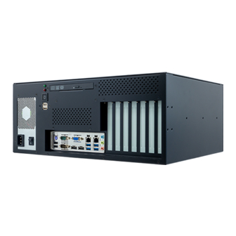
Page 14: System Overview
Chapter 2 Getting Started System Overview 2.2.1 Front View 2.2.2 Rear View BC-2602 SERIES USER MANUAL Page: 2-3... -
Page 15: Side View
Chapter 2 Getting Started 2.2.3 Side View Unit: mm 2.2.4 Quarter View BC-2602 SERIES USER MANUAL Page: 2-4... -
Page 16: Bc-2602 System Specifications
LAN1_USB1 2xUSB 3.1 Gen2 2xUSB 3.1 Gen1 LAN2_USB2 2xUSB 3.1 Gen1 2xUSB 2.0 KB_MS_USB 2xUSB 2.0 2xUSB 2.0 Internal USB_1 2xUSB 3.1 Gen1 2xUSB 3.1 Gen1 USB_2 2xUSB 2.0 2xUSB 2.0 USB_3 2xUSB 2.0 BC-2602 SERIES USER MANUAL Page: 2-5... - Page 17 2260, Co-lay with 4th PCIe slot 1 x SIM slot, to be used together with 3G or 4G/LTE SIM Slot M.2 module. Support Micro SIM card 1 x LPC pin header for TPM module BC-2602 SERIES USER MANUAL Page: 2-6...
- Page 18 Non-operation: 2G, 5-200Hz, X, Y, Z axis Vibration Environment 0°C ~ 40°C (32°F ~ 104°F) Operating Temp. -40°C ~ 85°C (-40°F ~ 185°F) Storage Temp. 20%~ 90% (non-condensing) Operation Humidity BC-2602 SERIES USER MANUAL Page: 2-7...
-
Page 19: Safety Precautions
If heavy stains are present, moisten a cloth with diluted neutral washing agent or alcohol and then wipe thoroughly with a dry cloth. • If dust is accumulated on the case surface, remove it by using a special vacuum cleaner for computers. BC-2602 SERIES USER MANUAL Page: 2-8... -
Page 20: Hardware Configuration
I/O Ports diagram, jumper & connector settings, and component locations. The following sections are included: • External I/O Ports Diagram • Jumper & Connector Quick Reference Table • Component Locations • Configuration and Jumper Settings • Connector Pin Assignments BC-2602 SERIES USER MANUAL Page: 3-1... -
Page 21: External I/O Ports Diagram
Chapter 3 Hardware Configuration External I/O Ports Diagram Power LED 2 x USB 2.0 Port HDD LED Power Switch Power Audio PS/2 Keyboard/ USB 2.0 Mouse Combo Connector COM2 4 x USB 3.1 Port COM1 BC-2602 SERIES USER MANUAL Page: 3-2... -
Page 22: Jumper & Connector Quick Reference Table
Speaker Header JSPK1 PS/2 + Dual USB 2.0 Ports KB_MS_USB (PS/2 Keyboard only) LAN + USB Connectors LAN1_USB1, LAN2_USB2 Mini PCI Express Slot M_PCIE1 (For C246/Q370 SKU Only) PCI Express Slots PCI_E1, PCI_E2, PCI_E3, BC-2602 SERIES USER MANUAL Page: 3-3... - Page 23 Front Audio Line In, Line Out JAUDIO1 and Mic In Connector Case Open Header I2C Wafers JI2C1, JI2C2 M.2 M-Key Slot M2_SSD NMI Header JNMI1 Flash BIOS Header JSPI_1 APS Header JAPS1 Micro SIM Card Socket SIM1 (rear side) BC-2602 SERIES USER MANUAL Page: 3-4...
-
Page 24: Main Board Component Locations
Make sure to ground yourself to prevent static charge while you are working on the connectors and jumpers. Use a grounding wrist strap and place all electronic components in any static-shielded devices. BC-2602 SERIES USER MANUAL Page: 3-5... -
Page 25: Main Board Jumper Setting
Note 3: C246 / Q370 SKU supports USB 3.1 Gen1 on LAN2_USB2. H310 SKU supports USB 2.0 on LAN2_USB2. Note 4: C246 / Q370 SKU supports 6 SATA ports on SATA1~SATA6. H310 SKU supports 4 SATA ports on SATA1~SATA4. BC-2602 SERIES USER MANUAL Page: 3-6... -
Page 26: Main Board Bottom View
Chapter 3 Hardware Configuration 3.3.3 Main Board Bottom View ATTEND SIM1 BC-2602 SERIES USER MANUAL Page: 3-7... -
Page 27: Main Board I/O View
Chapter 3 Hardware Configuration 3.3.4 Main Board I/O View PS/2 Keyboard COM2 LAN1 LAN2 Mouse Combo Audio USB 2.0 COM1 4 x USB 3.1 Port Connector BC-2602 SERIES USER MANUAL Page: 3-8... -
Page 28: How To Set Jumpers
PIN1 & PIN2 to create one setting by shorting. You can either connect PIN2 & PIN3 to create another setting. The same jumper diagrams are applied all through this manual. The figure below illustrates what the jumper diagrams look and what they represent. BC-2602 SERIES USER MANUAL Page: 3-9... - Page 29 Jumper Block looks like this Jumper Settings 2 pin Jumper close(enabled) Looks like this 3 pin Jumper 2-3 pin close(enabled) Looks like this Jumper Block 1-2 pin close(enabled) Looks like this BC-2602 SERIES USER MANUAL Page: 3-10...
-
Page 30: Setting Connectors And Jumpers
RS-485 DCD# RS-485- RS-485+ DTR# DSR# RTS# CTS# Notes: COM2 is selectable as RS-232, RS-422, RS-485 under BIOS setting. Default setting is RS-232. Please see Chapter 5 “Advanced – Super IO Configuration” for details. BC-2602 SERIES USER MANUAL Page: 3-11... -
Page 31: Com3, Com4, Com5, Com6 Connector (Com3 ~ Com6)
COM3, COM4: Pin 9 is selectable for RI, +5V or +12V by jumper setting. Default setting is RI. Please see “COM3 and COM4 PIN9 Definition Selection Guide” for details. COM5 and COM6 are available for C246/Q370 SKU only. BC-2602 SERIES USER MANUAL Page: 3-12... -
Page 32: Com3 And Com4 Pin9 Definition Selection Guide
3.5.3 COM3 and COM4 Pin9 Definition Selection Guide (JPCOM3, JPCOM4) Jumper Location: JPCOM3, JPCOM4 Description: COM3 and COM4 RI & Voltage Selection Jumper Setting Selection Jumper Illustration (Pin Closed) (Default Setting) JPCOM3/JPCOM4 JPCOM3/JPCOM4 JPCOM3/JPCOM4 BC-2602 SERIES USER MANUAL Page: 3-13... -
Page 33: Programmable Gpio Pin Header (Jdio1)
Programmable GPIO Pin Header (JDIO1) 3.5.4 Connector Location: JDIO1 Description: General Purpose Input / Output Pin Header ASSIGNMENT ASSIGNMENT VCC5 VCC12 DIN0 DOUT0 DIN1 DOUT1 JDIO1 DIN2 DOUT2 DIN3 DOUT3 DIN4 DOUT4 DIN5 DOUT5 DIN6 DOUT6 DIN7 DOUT7 BC-2602 SERIES USER MANUAL Page: 3-14... -
Page 34: Ps/2 Keyboard & Dual Usb 2.0 Port (Kb_Ms_Usb)
Supports mouse function on PS/2 by Y-cable. PS/2 PS/2: ASSIGNMENT ASSIGNMENT KB DATA KB CLK MS DATA MS CLK Dual USB 2.0 Dual USB 2.0: ASSIGNMENT ASSIGNMENT USB D+ USB D+ USB D- USB D- KB_MS_USB BC-2602 SERIES USER MANUAL Page: 3-15... -
Page 35: Displayport (Dp1, Dp2)
DP1 signals: ASSIGNMENT ASSIGNMENT DDP_B_P0 DDP_B_N0 DDP_B_P1 DDP_B_N1 DDP_B_P2 DDP_B_N2 DDP_B_P3 DDP_B_N3 DDP_B_AUX_ENJ DDP_B_AUX_P DDP_B_AUX_N DDP_B_HPD DP_PWR DP2 signals: ASSIGNMENT ASSIGNMENT DDP_C_P0 DDP_C_N0 DDP_C_P1 DDP_C_N1 DDP_C_P2 DDP_C_N2 DDP_C_P3 DDP_C_N3 DDP_C_AUX_ENJ DDP_C_AUX_P DDP_C_AUX_N DDP_C_HPD DP_PWR BC-2602 SERIES USER MANUAL Page: 3-16... -
Page 36: Vga (Video Graphics Array) Port (Vga1)
Chapter 3 Hardware Configuration 3.5.7 VGA (Video Graphics Array) Port (VGA1) Port Location: VGA1 Description: VGA (Video Graphics Array) Port ASSIGNMENT CRT_RED CRT_GREEN CRT_BLUE VGA1 CRT_VCC CRT_SDA CRT_HSYNC CRT_VSYNC CRT_SCL BC-2602 SERIES USER MANUAL Page: 3-17... -
Page 37: Front Panel Connector (Jfp1)
ASSIGNMENT SETTINGS ILLUSTRATION 1. HDD_LED+ HDD LED JFP1 3. HDD_LED- 2. PWR_LED+ Power LED JFP1 4. PWR_LED- 5. GND Reset Button JFP1 7. RST_BTN 6. PWR_BTN Power Button JFP1 8. GND 9. VCC5 JFP1 BC-2602 SERIES USER MANUAL Page: 3-18... -
Page 38: Lan & Usb Port (Lan1_Usb1, Lan2_Usb2)
Giga LAN Speed Indicator No LAN Switch/HUB connected Right Side LED Yellow Color Blinking LAN Message Active No LAN Message Active USB 3.1 signals (Gen.2): ASSIGNMENT ASSIGNMENT USB_TX_P USB D- USB_TX_N USB D+ USB_RX_P USB_RX_N BC-2602 SERIES USER MANUAL Page: 3-19... - Page 39 Left Side LED Green Color On 10/100Mbps LAN Speed Indicator Orange Color On Giga LAN Speed Indicator No LAN Switch/HUB connected Right Side LED Yellow Color Blinking LAN Message Active No LAN Message Active BC-2602 SERIES USER MANUAL Page: 3-20...
- Page 40 Chapter 3 Hardware Configuration USB 3.1 signals (Gen.1): ASSIGNMENT ASSIGNMENT USB_TX_P USB D- USB_TX_N USB D+ USB_RX_P USB_RX_N ASSIGNMENT ASSIGNMENT USB_TX_P USB D- USB_TX_N USB D+ USB_RX_P USB_RX_N BC-2602 SERIES USER MANUAL Page: 3-21...
-
Page 41: Line In, Line Out, Mic In Port (Audio1)
44 43 42 HD_LINE-IN-L 35 34 33 32 25 24 23 22 HD_LINE-IN-R 5 4 1 3 2 Line In Line Out: ASSIGNMENT LINE-OUT-L Line Out Mic In LINE-OUT-R AUDIO1 Mic In: ASSIGNMENT HD_MIC1-L_L HD_MIC1-R_L BC-2602 SERIES USER MANUAL Page: 3-22... -
Page 42: Embedded Display Port (Edp) Connector (Edp1)
It has advanced power-saving features including seamless refresh rate switching. It has become the new mainstream display panel interface for LCD panels with the realized higher resolution. BC-2602 SERIES USER MANUAL Page: 3-23... -
Page 43: Front Panel Audio Connector (Jaudio1)
Chapter 3 Hardware Configuration 3.5.12 Front Panel Audio Connector (JAUDIO1) Connector Location: JAUDIO1 Description: Front Panel Audio Connector ASSIGNMENT ASSIGNMENT MIC1-L MIC1-R LINE-IN-L LINE-IN-R LINE-OUT-L LINE-OUT-R JAUDIO1 BC-2602 SERIES USER MANUAL Page: 3-24... -
Page 44: Hardware Power Failure Selection (Jp_At1)
Chapter 3 Hardware Configuration 3.5.13 Hardware Power Failure Selection (JP_AT1) Jumper Location: JP_AT1 Description: Hardware Power Failure Selection Jumper Setting Selection Jumper Illustration (Pin Closed) Enable JP_AT1 Open Disable (Default Setting) JP_AT1 BC-2602 SERIES USER MANUAL Page: 3-25... -
Page 45: Pch Configuration / Recovery Selection (Jp2)
Chapter 3 Hardware Configuration 3.5.14 PCH Configuration / Recovery Selection (JP2) Jumper Location: JP2 Description: PCH Configuration / Recovery Selection Jumper Setting Selection Jumper Illustration (Pin Closed) Normal (Default Setting) Configure Recovery Open BC-2602 SERIES USER MANUAL Page: 3-26... -
Page 46: Flash Descriptor Override Selection (Jp3)
Chapter 3 Hardware Configuration 3.5.15 Flash Descriptor Override Selection (JP3) Jumper Location: JP3 Description: Flash Descriptor Override Selection Jumper Setting Selection Jumper Illustration (Pin Closed) Enable Open Disable (Default Setting) BC-2602 SERIES USER MANUAL Page: 3-27... -
Page 47: Vccio Voltage Selection (Jp6)
Chapter 3 Hardware Configuration 3.5.16 VCCIO Voltage Selection (JP6) Jumper Location: JP6 Description: VCCIO Voltage Selection Jumper Setting Selection Jumper Illustration (Pin Closed) 1.0V 0.95V (Default Setting) BC-2602 SERIES USER MANUAL Page: 3-28... -
Page 48: Usb Standby +5V / Normal Power Selection (Jp7)
Chapter 3 Hardware Configuration 3.5.17 USB Standby +5V / Normal Power Selection (JP7) Jumper Location: JP7 USB Standby +5V / Normal Power Selection Description: Jumper Setting Selection Jumper Illustration (Pin Closed) Normal (Default Setting) Standby +5V BC-2602 SERIES USER MANUAL Page: 3-29... -
Page 49: Parallel Port (Lpt) Connector (Lpt1)
Chapter 3 Hardware Configuration 3.5.18 Parallel Port (LPT) Connector (LPT1) Connector Location: LPT1 Description: Parallel Port Connector LPT1 ASSIGNMENT ASSIGNMENT PRN_STRBJ_R PRN_AFD PRN_R_D0 PRN_ERRJ PRN_R_D1 PRN_INIT PRN_R_D2 PRN_SLIN PRN_R_D3 PRN_R_D4 PRN_R_D5 PRN_R_D6 PRN_R_D7 PRN_ACKJ PRN_BUSY PRN_PE PRN_SLCT BC-2602 SERIES USER MANUAL Page: 3-30... -
Page 50: I2C Wafer (Ji2C1, Ji2C2)
Chapter 3 Hardware Configuration 3.5.19 I2C Wafer (JI2C1, JI2C2) Connector Location: JI2C1, JI2C2 Description: I2C Wafer ASSIGNMENT 3.3V I2C_SCL I2C_SDA JI2C1 JI2C2 3.5.20 Case Open Connector (JP5) Connector Location: JP5 Description: Case Open Connector ASSIGNMENT COPENJ BC-2602 SERIES USER MANUAL Page: 3-31... -
Page 51: Mini Pci Express Slot (For C246/Q370 Only) (M_Pcie1)
Note: C246 and Q370 SKUs support Mini-PCI Express Slot only. ASSIGNMENT ASSIGNMENT WAKE_N 3.3V_SB 1.5V CLKREQ# REFCLK+ REFCLK- PERST# PE_RX_N 3.3V_SB PE_RX_P M_PCIE1 1.5V SMB_CLK PE_TX_N SMB_DATA PE_TX_P USB_N USB_P 3.3V_SB 3.3V_SB 1.5V 3.3V_SB BC-2602 SERIES USER MANUAL Page: 3-32... -
Page 52: M-Key Slot (M2_Ssd)
PCIe Lane2 RX+ PCIe Lane2 TX- PCIe Lane2 TX+ PCIe Lane1 RX- PCIe Lane1 RX+ PCIe Lane1 TX- PCIe Lane1 TX+ PCIe Lane0 RX- PCIe Lane0 RX+ PCIe Lane0 TX- PCIe Lane0 TX+ PLTRST BC-2602 SERIES USER MANUAL Page: 3-33... - Page 53 Chapter 3 Hardware Configuration ASSIGNMENT ASSIGNMENT CLK REQ# PCIe CLK- Wake# PCIe CLK+ +3.3V +3.3V +3.3V BC-2602 SERIES USER MANUAL Page: 3-34...
-
Page 54: Pcie Bus (Pci_E1 (X16), Pci_E2 (X4), Pci_E3 (X4), Pci_E4
Description: 164-pin PCIE Bus (x16) PCI_E1 ASSIGNMENT ASSIGNMENT +12V PRSNT#1 +12V +12V +12V +12V SMB_CLK SMB_DATA +3.3V +3.3V +3.3V_AUX +3.3V WAKE# PERST# RSVD REFCLK+ HSOP0 REFCLK- HSON0 HSIP0 PRSNT#2 HSIN0 HSOP1 RSVD HSON1 HSIP1 HSIN1 HSOP2 BC-2602 SERIES USER MANUAL Page: 3-35... - Page 55 RSVD HSOP4 RSVD HSON4 HSIP4 HSIN4 HSOP5 HSON5 HSIP5 HSIN5 HSOP6 HSON6 HSIP6 HSIN6 HSOP7 HSON7 HSIP7 PRSNT#2 HSIN7 HSOP8 RSVD HSON8 HSIP8 HSIN8 HSOP9 HSON9 HSIP9 HSIN9 HSOP10 HSON10 HSIP10 HSIN10 HSOP11 HSON11 BC-2602 SERIES USER MANUAL Page: 3-36...
- Page 56 Chapter 3 Hardware Configuration ASSIGNMENT ASSIGNMENT HSIP11 HSIN11 HSOP12 HSON12 HSIP12 HSIN12 HSOP13 HSON13 HSIP13 HSIN13 HSOP14 HSIN14 HSIP14 HSIN14 HSIP15 HSIN15 HSIP15 PRSNT#2 HSIN15 RSVD BC-2602 SERIES USER MANUAL Page: 3-37...
- Page 57 PCI_E2 (x4) is supported in C246 and Q370 SKUs only. PCI_E2 ASSIGNMENT ASSIGNMENT +12V PRSNT#1 +12V +12V +12V +12V SMB_CLK SMB_DATA +3.3V +3.3V +3.3V_AUX +3.3V WAKE# PERST# RSVD REFCLK+ HSOP0 REFCLK- HSON0 HSIP0 PRSNT#2 HSIN0 HSOP1 RSVD HSON1 HSIP1 HSIN1 HSOP2 HSON2 HSIP2 BC-2602 SERIES USER MANUAL Page: 3-38...
- Page 58 Chapter 3 Hardware Configuration ASSIGNMENT ASSIGNMENT HSIN2 HSOP3 HSON3 HSIP3 RSVD HSIN3 PRSNT#2 RSVD BC-2602 SERIES USER MANUAL Page: 3-39...
- Page 59 PCI_E3 (x4) is supported in C246 and Q370 SKUs only. PCI_E3 ASSIGNMENT ASSIGNMENT +12V PRSNT#1 +12V +12V +12V +12V SMB_CLK SMB_DATA +3.3V +3.3V +3.3V_AUX +3.3V WAKE# PERST# RSVD REFCLK+ HSOP0 REFCLK- HSON0 HSIP0 PRSNT#2 HSIN0 HSOP1 RSVD HSON1 HSIP1 HSIN1 HSOP2 HSON2 HSIP2 BC-2602 SERIES USER MANUAL Page: 3-40...
- Page 60 Chapter 3 Hardware Configuration ASSIGNMENT ASSIGNMENT HSIN2 HSOP3 HSON3 HSIP3 RSVD HSIN3 PRSNT#2 RSVD BC-2602 SERIES USER MANUAL Page: 3-41...
- Page 61 PCI_E4 ASSIGNMENT ASSIGNMENT +12V PRSNT#1 +12V +12V +12V +12V SMB_CLK SMB_DATA +3.3V +3.3V +3.3V_AUX +3.3V WAKE# PERST# RSVD REFCLK+ HSOP0 REFCLK- HSON0 HSIP0 PRSNT#2 HSIN0 HSOP1 RSVD HSON1 HSIP1 HSIN1 HSOP2 HSON2 HSIP2 HSIN2 BC-2602 SERIES USER MANUAL Page: 3-42...
- Page 62 Chapter 3 Hardware Configuration ASSIGNMENT ASSIGNMENT HSOP3 HSON3 HSIP3 RSVD HSIN3 PRSNT#2 RSVD BC-2602 SERIES USER MANUAL Page: 3-43...
- Page 63 PCI_E5 (x1) is supported in C246 and Q370 SKUs only. PCI_E5 ASSIGNMENT ASSIGNMENT +12V PRSNT#1 +12V +12V +12V +12V SMB_CLK SMB_DATA +3.3V +3.3V +3.3V_AUX +3.3V WAKE# PERST# RSVD REFCLK+ HSOP0 REFCLK- HSON0 HSIP0 PRSNT#2 HSIN0 BC-2602 SERIES USER MANUAL Page: 3-44...
-
Page 64: Pci Bus Slot (Pci1, Pci2)
3.5.24 PCI Bus Slot (PCI1, PCI2) Connector Location: PCI1, PCI2 Description: 124-pin PCI Bus Slot PCI1 / PCI2 ASSIGNMENT ASSIGNMENT -12V TRST# +12V INTA# INTB# INTC# INTD# RST# GNT# REQ# AD31 AD30 AD29 +3.3V AD28 AD27 AD26 AD25 BC-2602 SERIES USER MANUAL Page: 3-45... - Page 65 TRDY# DEVSEL# STOP# LOCK# +3.3V PERR# SDONE +3.3V SB0# SERR# +3.3V C/BE1# AD15 AD14 +3.3V AD13 AD12 AD11 AD10 AD09 AD08 C/BE0# AD07 +3.3V +3.3V AD06 AD05 AD04 AD03 AD02 AD01 AD00 ACK64# REQ64# BC-2602 SERIES USER MANUAL Page: 3-46...
-
Page 66: Cpu / System Fan Connector
3.5.25 CPU / System Fan Connector (CPU_FAN1, SYS_FAN1, SYS_FAN2) Connector Location: CPU_FAN1, SYS_FAN1 Description: CPU Fan Connector (CPU_FAN1), System Fan Connector 1 (SYS_FAN1) ASSIGNMENT CPU_FAN1 +12V CPU_FANTAC CPU_FANCTRL SYS_FAN1 Connector Location: SYS_FAN2 Description: System Fan Connector 2 ASSIGNMENT +12V SYS_FAN2 BC-2602 SERIES USER MANUAL Page: 3-47... -
Page 67: Serial Ata (Sata) Connector (Sata1 ~ Sata6)
Connector Location: SATA1, SATA2, SATA3, SATA4, SATA5, SATA6 Description: SATA Connectors SATA1 Pin Assignment: ASSIGNMENT SATA_TXP0 SATA_TXN0 SATA1/ SATA_RXN0 SATA3/ SATA_RXP0 SATA5 SATA2 Pin Assignment: ASSIGNMENT SATA_TXP1 SATA_TXN1 SATA_RXN1 SATA2/ SATA_RXP1 SATA4/ SATA6 SATA3 Pin Assignment: ASSIGNMENT SATA_TXP2 SATA_TXN2 SATA_RXN2 SATA_RXP2 BC-2602 SERIES USER MANUAL Page: 3-48... - Page 68 ASSIGNMENT SATA_TXP3 SATA_TXN3 SATA_RXN3 SATA_RXP3 SATA5 Pin Assignment: ASSIGNMENT SATA_TXP4 SATA_TXN4 SATA_RXN4 SATA_RXP4 SATA6 Pin Assignment: ASSIGNMENT SATA_TXP5 SATA_TXN5 SATA_RXN5 SATA_RXP5 Notes: C246 SKU supports SATA1~SATA6. Q370 SKU supports SATA1~SATA6. H310 SKU supports SATA1~SATA4. BC-2602 SERIES USER MANUAL Page: 3-49...
-
Page 69: Internal Usb 3.1 Connector (Usb1)
Chapter 3 Hardware Configuration 3.5.27 Internal USB 3.1 Connector (USB1) Connector Location: USB1 Description: Internal USB 3.1 Connector ASSIGNMENT ASSIGNMENT USB D+ USB_RX_N USB D- USB_RX_P USB_TX_P USB_TX_N USB_TX_N USB_TX_P USB_RX_P USB D- USB_RX_N USB D+ USB1 BC-2602 SERIES USER MANUAL Page: 3-50... -
Page 70: Internal Usb 2.0 Connector (Usb2, Usb3, Usb4)
Chapter 3 Hardware Configuration 3.5.28 Internal USB 2.0 Connector (USB2, USB3, USB4) Connector Location: USB2, USB3, USB4 Description: Internal USB 2.0 Connector ASSIGNMENT ASSIGNMENT USB D- USB D- USB D+ USB D+ USB2/ USB3/ USB4 BC-2602 SERIES USER MANUAL Page: 3-51... -
Page 71: Speaker Connector (Jspk1)
Chapter 3 Hardware Configuration 3.5.29 Speaker Connector (JSPK1) Connector Location: JSPK1 Description: Speaker Connector ASSIGNMENT JSPK1 SPKR_VCC SPKR_SIGNAL SPKR_SIGNAL SPKR_SIGNAL BC-2602 SERIES USER MANUAL Page: 3-52... -
Page 72: Power Input Connector (Atx_Pwr1, Atx_Pwr2)
3.5.30 Power Input Connector (ATX_PWR1, ATX_PWR2) Connector Location: ATX_PWR1 Description: ATX Power Connector ASSIGNMENT ASSIGNMENT +3.3V +3.3V +3.3V -12V PSON ATX_PWR1 +5V_SB +12V +12V +12V Connector Location: ATX_PWR2 Description: Power Connector ASSIGNMENT ASSIGNMENT +12V +12V ATX_PWR2 BC-2602 SERIES USER MANUAL Page: 3-53... -
Page 73: Low Pin Count (Lpc) Connector (Jlpc1)
Chapter 3 Hardware Configuration 3.5.31 Low Pin Count (LPC) Connector (JLPC1) Connector Location: JLPC1 Description: LPC Connector ASSIGNMENT ASSIGNMENT FRAME RESET VCC5 LAD3 LAD2 VCC3 LAD1 LAD0 JLPC1 SMBCLK SMBDATA 3VSB SERIRQ CLK RUN SUS_TAT DREQ0 BC-2602 SERIES USER MANUAL Page: 3-54... -
Page 74: Clear Cmos Data Selection (Jcmos1)
Step 4. Power on the PC and the PC will then auto-reboot for once in order to set SoC’s register. Step 5. Done! Jumper Setting Selection Jumper Illustration (Pin Closed) Open Normal (Default Setting) JCMOS1 Clear CMOS JCMOS1 3.5.33 NMI Header (JNMI1) Connector Location: JNMI1 Description: NMI Header ASSIGNMENT 3.3V JNMI1 BC-2602 SERIES USER MANUAL Page: 3-55... -
Page 75: Flash Bios Header (Jspi_1)
Description: Flash BIOS Header ASSIGNMENT ASSIGNMENT +3.3V SCLK MISO MOSI HOLD# JSPI_1 3.5.35 APS Header (JAPS1) Connector Location: JAPS1 Description: APS Header ASSIGNMENT ASSIGNMENT +3.3V +3.3V SLP_S5# SLP_S3# JAPS1 SLP_A# RTC RST# SLP_S4# SYS RST# Power BTN BC-2602 SERIES USER MANUAL Page: 3-56... -
Page 76: Micro Sim Card Socket (Sim1)
3.5.36 Micro SIM Card Socket (SIM1) Connector Location: SIM1 Description: Micro SIM Push/Push type (located on the rear side of BC-2602) ASSIGNMENT SIM PWR ATTEND SIM RST SIM VPP SIM CLK SIM DATA Reserved Reserved SIM1 BC-2602 SERIES USER MANUAL Page: 3-57... -
Page 77: Software Utilities
• Installing LAN Driver Utility • Installing Sound Driver Utility ® • Installing Intel Management Engine Components Driver Installer • Installing Intel Rapid Storage Utility ® • Installing Intel Serial I/O Driver Utility ® BC-2602 SERIES USER MANUAL Page: 4-1... - Page 78 Chapter 4 Software Utilities Introduction Enclosed with the BC-2602 Series package is our driver utilities contained in a DVD-ROM disk. Refer to the following table for driver locations: Filename (Assume that Purpose DVD-ROM drive is D:) D:\Driver\Platform\1_Main Chip\Win10(64-bit) Intel(R) Chipset Device Software installer...
-
Page 79: Introduction
(depending on your OS platform). Click SetupChipset.exe file for driver installation. Follow the on-screen instructions to install the driver. Once the installation is completed, shut down the system and restart BC-2602 for the changes to take effect. BC-2602 SERIES USER MANUAL Page: 4-3... -
Page 80: Installing Graphics Driver Utility
OS platform). Click the igxpin.exe file for driver installation. Follow the on-screen instructions to complete the installation. Once the installation is completed, shut down the system and restart BC-2602 for the changes to take effect. BC-2602 SERIES USER MANUAL Page: 4-4... -
Page 81: Installing Lan Driver Utility
OS platform). Click LAN_WIN10_64_23.5.2.exe file for driver installation. Follow the on-screen instructions to complete the installation. Once the installation is completed, shut down the system and restart BC-2602 for the changes to take effect. BC-2602 SERIES USER MANUAL Page: 4-5... -
Page 82: Installing Sound Driver Utility
OS platform). Click the Setup.exe file for driver installation. Follow the on-screen instructions to complete the installation. Once the installation is completed, shut down the system and restart BC-2602 for the changes to take effect. BC-2602 SERIES USER MANUAL Page: 4-6... -
Page 83: Intel ® Management Engine Components Driver Installer Installation
Select H310 or Q370&C246 SKU. Click SetupME.exe file for ME driver installation. Follow the on-screen instructions to complete the installation. Once the installation is completed, shut down the system and restart BC-2602 for the changes to take effect. BC-2602 SERIES USER MANUAL Page: 4-7... -
Page 84: Installing Raid Utility (Only For C246/Q370, Optional)
Press <Del> to access the BIOS Setup Utility program when prompted during the Power-On Self-Test (POST). Enter Chipset > PCH-IO Configuration > SATA Configuration menu screen and select “RAID” option for SATA Controller(s) option item. See the picture below: BC-2602 SERIES USER MANUAL Page: 4-8... - Page 85 Press F4 to save and validate the changed BIOS configuration and reset the system. Press <Del> to enter the BIOS Setup Utility program again and the Intel(R) Rapid Storage Technology option item will display under the Advanced menu screen as below: BC-2602 SERIES USER MANUAL Page: 4-9...
- Page 86 Chapter 4 Software Utilities Select the Intel(R) Rapid Storage Technology option item and press <Enter>, and the following screen will display. Select a RAID level that you want to enter and press <Enter>. BC-2602 SERIES USER MANUAL Page: 4-10...
- Page 87 The hard drive(s) and hard drive information of the RAID level you selected in the previous step will display: Heed that in the user interface, the hard drive(s) and hard drive information listed for your system will differ from the example above. BC-2602 SERIES USER MANUAL Page: 4-11...
- Page 88 Follow the on-screen instructions to complete the installation. Once the installation is completed, shut down the system and restart BC-2602 for the changes to take effect. Note: The RAID utility is not supported for H310 SKU. BC-2602 SERIES USER MANUAL Page: 4-12...
-
Page 89: Installing Intel ® Serial I/O Driver Utility
Select Windows 10 (64-bit) for your OS platform. Click the SetupSerialIO.exe file for driver installation. Follow the on-screen instructions to complete the installation. Once the installation is completed, shut down the system and restart BC-2602 for the changes to take effect. BC-2602 SERIES USER MANUAL Page: 4-13... -
Page 90: Bios Setup
The BIOS Setup Utilities consist of the following menu items: Main Menu • Advanced Menu • Chipset Menu • Security Menu • Boot Menu • Save & Exit Menu • BC-2602 SERIES USER MANUAL Page: 5-1... -
Page 91: Introduction
EFI BIOS provides an user interface that allows you to modify hardware configuration, e.g. change the system date and time, enable/disable a system component, determine bootable device priority, set up personal password, etc., which is convenient for engineers to perform modifications and customize the computer BC-2602 SERIES USER MANUAL Page: 5-2... -
Page 92: Accessing Setup Utility
POST message will be displayed: Figure 5-2. POST Screen with AMI Logo Press <Del> or <Esc> to access the Setup Utility program and the Main menu of the Aptio Setup Utility will appear on the screen as below: BC-2602 SERIES USER MANUAL Page: 5-3... - Page 93 English. You may use <↑> or <↓> key to select among the items and press <Enter> to confirm and enter the sub-menu. The following table provides the list of the navigation keys that you can use while operating the BIOS setup menu. BC-2602 SERIES USER MANUAL Page: 5-4...
- Page 94 Load the previous configuration values. <F3> Load the default configuration values. <F4> Save the current values and exit the BIOS setup menu. <Esc> Close the sub-menu. Trigger the confirmation to exit BIOS setup menu. BC-2602 SERIES USER MANUAL Page: 5-5...
-
Page 95: Main
Name No changeable options Displays the name of the PCH. PCH SKU No changeable options Displays the SKU for the PCH. Stepping No changeable options Displays the stepping of the PCH. BC-2602 SERIES USER MANUAL Page: 5-6... - Page 96 The “Day” is automatically changed. System Time Hour, minute, second Sets the system time. The format is [Hour: Minute: Second]. Users can directly enter values or use <+> or <-> arrow keys to increase/decrease it. BC-2602 SERIES USER MANUAL Page: 5-7...
-
Page 97: Advanced
Sub-Menu S5 RTC Wake Parameters. Super IO Configuration Sub-Menu System Super I/O Chip Parameters. USB Configuration Sub-Menu USB Configuration Parameters. NVMe Configuration Sub-Menu NVMe Device Options Settings. Network Stack Configuration Sub-Menu Network Stack Settings. BC-2602 SERIES USER MANUAL Page: 5-8... -
Page 98: Advanced - Cpu Configuration
SMX (Secure Mode No changeable options Secure Mode extensions support. Extensions) / TXT When enabled, VMM can utilize the Intel Virtualization - Disabled additional hardware capabilities Technology - Enabled (default) provided by Vanderpool Technology. BC-2602 SERIES USER MANUAL Page: 5-9... -
Page 99: Advanced - Pch-Fw Configuration
Description/Purpose ME Firmware Version No changeable options Displays the ME Firmware Version. ME Firmware Mode No changeable options Displays the ME Firmware Mode. ME Firmware SKU No changeable options Displays the ME Firmware SKU. BC-2602 SERIES USER MANUAL Page: 5-10... -
Page 100: Advanced - Trusted Computing
TPM module vendor. Security Device - Enable (default) Enables or Disables BIOS support for Support - Disable security device. O.S. will not show Security Device. TCG EFI protocol and INT1A interface will not be available. BC-2602 SERIES USER MANUAL Page: 5-11... -
Page 101: Advanced - Acpi Settings
SUSPEND (default) button is pressed. Lock Legacy - Disabled (default) Enables or Disables Lock of Legacy Resources - Enabled Resources. - Disabled (default) S3 Video Repost Enables or Disables S3 Video Repost. - Enabled BC-2602 SERIES USER MANUAL Page: 5-12... -
Page 102: Advanced - Hardware Monitor
Displays the voltage level of VCORE VCORE No changeable options in supply. Displays the voltage level of VCC5V VCC5V No changeable options in supply. Displays the voltage level of VCC12 VCC12 No changeable options in supply. BC-2602 SERIES USER MANUAL Page: 5-13... -
Page 103: Smart Fan Mode Configuration
CPU Fan Smart Fan Control - Auto Duty-Cycle Mode Fan. (default) Manual mode fan control. Users can Manual Duty Mode Numeric (from 1 to 100) write expected duty cycle (PWM fan type) from 1 to 100. BC-2602 SERIES USER MANUAL Page: 5-14... -
Page 104: Advanced - Super Io Watchdog
Enables/Disables F81866 Watchdog Enable Watchdog - Disabled (default) timer settings. - 1s (default) Watchdog timer unit Watchdog timer unit. - 60s Numeric Count for Timer (Seconds) The number of count for Timer. (from 10 to 255) BC-2602 SERIES USER MANUAL Page: 5-15... -
Page 105: Advanced - S5 Rtc Wake Settings
Enters 0-59 to set the wake-up Wake up second Numeric (from 0 to 59) second. Enters 1-5 to set the increased Wake up minute increase Numeric (from 1 to 5) minute(s) for dynamic wake-up time. BC-2602 SERIES USER MANUAL Page: 5-16... -
Page 106: Advanced - Super Io Configuration
Sets Parameters of Serial Port 5 (COME). (for Q370/C246 only) Serial Port 6 Configuration Sub-Menu Sets Parameters of Serial Port 6 (COMF). (for Q370/C246 only) Parallel Port Sub-Menu Sets Parameters of Parallel Port (LPT). BC-2602 SERIES USER MANUAL Page: 5-17... -
Page 107: Super Io Configuration - Serial Port 1 Configuration
No changeable options Serial Port 1. Possible - Auto (default) Selects IRQ and I/O resource for - IO=3F8h; IRQ=4; Serial Port 1. - IO=3F8h; IRQ=3,4,5,6,7,10,11; - IO=2F8h; IRQ=3,4,5,6,7,10,11; - IO=3E8h; IRQ=3,4,5,6,7,10,11; - IO=2E8h; IRQ=3,4,5,6,7,10,11; BC-2602 SERIES USER MANUAL Page: 5-18... -
Page 108: Super Io Configuration - Serial Port 2 Configuration
Selects IRQ and I/O resource for - IO=2F8h; IRQ=3; Serial Port 2. - IO=3F8h; IRQ=3,4,5,6,7,10,11; Change Settings - IO=2F8h; IRQ=3,4,5,6,7,10,11; - IO=3E8h; IRQ=3,4,5,6,7,10,11; - IO=2E8h; IRQ=3,4,5,6,7,10,11; - RS-232 (default) Mode - RS-422 Selects COM2 mode. - RS-485 BC-2602 SERIES USER MANUAL Page: 5-19... -
Page 109: Super Io Configuration - Serial Port 3 Configuration
No changeable options Serial Port 3. - Auto (default) Selects IRQ and I/O resource for - IO=3E8h; IRQ=7; Serial Port 3. - IO=3E8h; IRQ=3,4,5,6,7,10,11; Change Settings - IO=2E8h; IRQ=3,4,5,6,7,10,11; - IO=2F0h; IRQ=3,4,5,6,7,10,11; - IO=2E0h; IRQ=3,4,5,6,7,10,11; BC-2602 SERIES USER MANUAL Page: 5-20... -
Page 110: Super Io Configuration - Serial Port 4 Configuration
No changeable options Serial Port 4. - Auto (default) Selects IRQ and I/O resource for - IO=2E8h; IRQ=6; Serial Port 4. - IO=3E8h; IRQ=3,4,5,6,7,10,11; Change Settings - IO=2E8h; IRQ=3,4,5,6,7,10,11; - IO=2F0h; IRQ=3,4,5,6,7,10,11; - IO=2E0h; IRQ=3,4,5,6,7,10,11; BC-2602 SERIES USER MANUAL Page: 5-21... -
Page 111: Super Io Configuration - Serial Port 5 Configuration
No changeable options Serial Port 5. - Auto (default) Selects IRQ and I/O resource for - IO=2F0h; IRQ=10; Serial Port 5. - IO=3E8h; IRQ=3,4,5,6,7,10,11; Change Settings - IO=2E8h; IRQ=3,4,5,6,7,10,11; - IO=2F0h; IRQ=3,4,5,6,7,10,11; - IO=2E0h; IRQ=3,4,5,6,7,10,11; BC-2602 SERIES USER MANUAL Page: 5-22... -
Page 112: Super Io Configuration - Serial Port 6 Configuration
No changeable options Serial Port 6. - Auto (default) Selects IRQ and I/O resource for - IO=2E0h; IRQ=11; Serial Port 6. - IO=3E8h; IRQ=3,4,5,6,7,10,11; Change Settings - IO=2E8h; IRQ=3,4,5,6,7,10,11; - IO=2F0h; IRQ=3,4,5,6,7,10,11; - IO=2E0h; IRQ=3,4,5,6,7,10,11; BC-2602 SERIES USER MANUAL Page: 5-23... -
Page 113: Super Io Configuration - Parallel Port Configuration
After the mode is changed, Mode - EPP-1.7 and SPP Mode reset the system to reflect the actual - ECP Mode device settings. - ECP and EPP 1.9 Mode - ECP and EPP 1.7 Mode BC-2602 SERIES USER MANUAL Page: 5-24... -
Page 114: Advanced - Usb Configuration
Optical drives Mass Storage - Forced FDD are emulated as 'CD-ROM'. Drives Devices: [drive(s)] - Hard Disk with no media will be emulated - CD-ROM according to a drive type. BC-2602 SERIES USER MANUAL Page: 5-25... -
Page 115: Advanced - Nvme Configuration
Chapter 5 BIOS Setup 5.4.10 Advanced – NVMe Configuration Menu Path Advanced > NVMe Configuration NVMe Configuration Screen BIOS Setting Options Description/Purpose NVMe Configuration No changeable options Displays NVMe device. BC-2602 SERIES USER MANUAL Page: 5-26... -
Page 116: Advanced - Network Stack Configuration
- Disabled (default) Enables or Disables UEFI Network Network Stack - Enabled Stack. Enables Ipv4 PXE Boot Support. If - Disabled (default) Ipv4 PXE Support disabled, Ipv4 PXE boot option will - Enabled not be created. BC-2602 SERIES USER MANUAL Page: 5-27... - Page 117 PXE boot wait time Numeric (from 0 to 5) boot to abort after the Esc key is pressed. Number of times that the media Media detect count Numeric (from 1 to 50) presence will be checked. BC-2602 SERIES USER MANUAL Page: 5-28...
-
Page 118: Chipset
This menu allows users to configure advanced Chipset settings such as System Agent (SA) and PCH-IO configuration parameters. Chipset Screen BIOS Setting Options Description/Purpose System Agent (SA) Parameters Sub-Menu System Agent (SA) Parameters. PCH-IO Configuration Sub-Menu PCH Parameters. BC-2602 SERIES USER MANUAL Page: 5-29... -
Page 119: Chipset - System Agent (Sa) Configuration
System Agent (SA) Configuration Screen BIOS Setting Options Description/Purpose Memory Configuration Sub-Menu Memory Configuration. Graphics Configuration Sub-Menu Graphics Configuration. PEG Port Configuration Sub-Menu PEG Port Configuration. - Disabled VT-d Enables or Disables VT-d function. - Enabled (default) BC-2602 SERIES USER MANUAL Page: 5-30... -
Page 120: System Agent (Sa) Configuration - Memory Configuration
No changeable options Displays the size of DIMM1. DIMM2 No changeable options Displays the size of DIMM2. (for Q370/C246 only) DIMM3 No changeable options Displays the size of DIMM3. DIMM4 No changeable options Displays the size of DIMM4. (for Q370/C246 only) BC-2602 SERIES USER MANUAL Page: 5-31... -
Page 121: System Agent (Sa) Configuration - Graphics Configuration
The Graphics Configuration allows users to configure the display settings for the LCD panel. Graphics Configuration Screen BIOS Setting Options Description/Purpose - Auto (default) Selects which Graphics device should Primary Display - IGFX be Primary Display. BC-2602 SERIES USER MANUAL Page: 5-32... -
Page 122: System Agent (Sa) Configuration - Peg Port Configuration
No changeable options information. - Disabled Enable Root Port - Enabled Enables or Disables the Root Port. - Auto (default) - Auto (default) - Gen1 Max Link Speed Configures PCI-E1 Max Speed. - Gen2 - Gen3 BC-2602 SERIES USER MANUAL Page: 5-33... -
Page 123: Chipset - Pch Io Configuratioin
- Enabled (default) to wake up the system. Specifies the state to go to when AC - Power On Restore AC Power Loss power is re-applied following a - Power Off (default) power failure (G3 state). BC-2602 SERIES USER MANUAL Page: 5-34... -
Page 124: Pch-Io Configuration - Pci Express Configuration
PCI Express x4 Slot settings. PCI Express x1 – SLOT#5 Sub-Menu PCI Express x1 Slot settings. (for Q370/C246 only) Mini PCI Express x1 SLOT Sub-Menu Mini PCI Express x1 Slot settings. (for Q370/C246 only) BC-2602 SERIES USER MANUAL Page: 5-35... - Page 125 • Disabled - Disables ASPM. - Auto - Disabled (default) L1 Substates - L1.1 PCI Express L1 Substates settings. - L1.1 & L1.2 - Disabled (default) Hot Plug Enables or Disables Hot Plug support. - Enabled BC-2602 SERIES USER MANUAL Page: 5-36...
-
Page 126: Pch-Io Configuration - Pci Express Configuration - Pci Express X4 - Slot#3 (For Q370 / C246 Sku Only)
- Disabled (default) Sets the ASPM Level: - L0s • L0s - Force all links to L0s state. ASPM - L1 • Auto - BIOS auto configure. - L0sL1 • Disabled - Disables ASPM. - Auto BC-2602 SERIES USER MANUAL Page: 5-37... - Page 127 Configuration > PCI Express x4 – SLOT#4 PCI Express x4 Slot#4 Screen BIOS Setting Options Description/Purpose - Disabled Enables or Disables the PCI PCI Express x4 – SLOT#4 - Enabled (default) Express x4 slot. BC-2602 SERIES USER MANUAL Page: 5-38...
- Page 128 Hot Plug - Enabled support. - Auto (default) - Gen1 PCIe Speed Configures PCIe Speed. - Gen2 - Gen3 - PCIe X4 slot (default) PCIe SLOT4 Select PCIe SLOT#4 function selection. - M.2 NVMe slot BC-2602 SERIES USER MANUAL Page: 5-39...
-
Page 129: Pch-Io Configuration - Pci Express Configuration - Pci Express X1 - Slot#5 (For Q370 / C246 Sku Only)
L1 Substates - L1.1 PCI Express L1 Substates settings - L1.1 & L1.2 - Disabled (default) Hot Plug Enables or Disables Hot Plug support. - Enabled PCIe Speed - Auto (default) Configures PCIe speed. BC-2602 SERIES USER MANUAL Page: 5-40... -
Page 130: Configuration
ASPM - L1 • Auto - BIOS auto configure. - L0sL1 • Disabled - Disables ASPM. - Auto - Disabled (default) L1 Substates - L1.1 PCI Express L1 Substates settings. - L1.1 & L1.2 BC-2602 SERIES USER MANUAL Page: 5-41... - Page 131 - Enabled - AHCI (default) SATA Mode Determines how SATA controller(s) operate. - Intel RST (RAID) Serial ATA Port 1 – 6 (ports 5-6 for No changeable options Displays the SATA device’s name. Q370/C246 only) BC-2602 SERIES USER MANUAL Page: 5-42...
- Page 132 Chapter 5 BIOS Setup BIOS Setting Options Description/Purpose - Disabled Port 1 - 6 Enables or Disables SATA Port Device. - Enabled (default) - Disabled (default) Enables or Disables SATA Port Device HotPlug HotPlug - Enabled function. BC-2602 SERIES USER MANUAL Page: 5-43...
-
Page 133: Security
Setup utility. Security Screen BIOS Setting Options Description/Purpose Administrator Password Password can be 3-20 Specifies the administrator alphanumeric characters. password. User Password Password can be 3-20 Specifies the user password. alphanumeric characters. BC-2602 SERIES USER MANUAL Page: 5-44... - Page 134 <Enter>, and the password dialog entry box appears. Select the configured Administrator Password or User Password that you want to delete. Leave the dialog box blank and press <Enter>. Press <Enter> again when the password confirmation box appears. BC-2602 SERIES USER MANUAL Page: 5-45...
-
Page 135: Boot
Specifies the power-on state of the Bootup NumLock State - Off NumLock Key. - Disabled (default) Enables or Disables Quiet Boot Quiet Boot - Enabled option. - [Drive(s)] Boot Option #1~#n Sets the system boot order. - Disabled BC-2602 SERIES USER MANUAL Page: 5-46... -
Page 136: Save & Exit
Discard Changes and Reset to discard any changes you have made and restore the factory BIOS defaults. Load User Defaults You may simply press F3 at any time to load the Optimized Values which resets all BIOS settings to the factory defaults. Save & Exit Screen BC-2602 SERIES USER MANUAL Page: 5-47... - Page 137 Saves the changes done so far as User Save as User Defaults No changeable options Defaults. Restores the User Defaults to all the Restore User Defaults No changeable options setup options. Forces to boot from selected Boot Override - [Drive(s)] [drive(s)]. BC-2602 SERIES USER MANUAL Page: 5-48...
-
Page 138: Appendix A Technical Summary
BC-2602 resources. The following topics are included: • BC-2602 Block Diagram • Interrupt Map • I/O Map • Memory Map • DMA Map • Configuring WatchDog Timer • Flash BIOS Update BC-2602 SERIES USER MANUAL Page: A-1... -
Page 139: Ba-2602 Block Diagram
LPC SLOT Connector (SLB9665TT2.0-5.63) COM 2 RS232/422/485 HW monitor FINTEK COM 3 (5V/12V) RS232 LPC SIO PS/2 Keyboard COM 4 Mouse F81866AD-I (5V/12V) RS232 COM 5 LPT Port RS232 (wafer pitch2.0) COM 6 RS232 BC-2602 SERIES USER MANUAL Page: A-2... -
Page 140: Interrupt Map
IRQ 64 Microsoft ACPI-Compliant System IRQ 65 Microsoft ACPI-Compliant System IRQ 66 Microsoft ACPI-Compliant System IRQ 67 Microsoft ACPI-Compliant System IRQ 68 Microsoft ACPI-Compliant System IRQ 69 Microsoft ACPI-Compliant System IRQ 70 Microsoft ACPI-Compliant System BC-2602 SERIES USER MANUAL Page: A-3... - Page 141 IRQ 97 Microsoft ACPI-Compliant System IRQ 98 Microsoft ACPI-Compliant System IRQ 99 Microsoft ACPI-Compliant System IRQ 100 Microsoft ACPI-Compliant System IRQ 101 Microsoft ACPI-Compliant System IRQ 102 Microsoft ACPI-Compliant System IRQ 103 Microsoft ACPI-Compliant System BC-2602 SERIES USER MANUAL Page: A-4...
- Page 142 IRQ 132 Microsoft ACPI-Compliant System IRQ 133 Microsoft ACPI-Compliant System IRQ 134 Microsoft ACPI-Compliant System IRQ 135 Microsoft ACPI-Compliant System IRQ 136 Microsoft ACPI-Compliant System IRQ 137 Microsoft ACPI-Compliant System IRQ 138 Microsoft ACPI-Compliant System BC-2602 SERIES USER MANUAL Page: A-5...
- Page 143 IRQ 165 Microsoft ACPI-Compliant System IRQ 166 Microsoft ACPI-Compliant System IRQ 167 Microsoft ACPI-Compliant System IRQ 168 Microsoft ACPI-Compliant System IRQ 169 Microsoft ACPI-Compliant System IRQ 170 Microsoft ACPI-Compliant System IRQ 171 Microsoft ACPI-Compliant System BC-2602 SERIES USER MANUAL Page: A-6...
- Page 144 IRQ 200 Microsoft ACPI-Compliant System IRQ 201 Microsoft ACPI-Compliant System IRQ 202 Microsoft ACPI-Compliant System IRQ 203 Microsoft ACPI-Compliant System IRQ 204 Microsoft ACPI-Compliant System IRQ 256 Microsoft ACPI-Compliant System IRQ 257 Microsoft ACPI-Compliant System BC-2602 SERIES USER MANUAL Page: A-7...
- Page 145 IRQ 284 Microsoft ACPI-Compliant System IRQ 285 Microsoft ACPI-Compliant System IRQ 286 Microsoft ACPI-Compliant System IRQ 287 Microsoft ACPI-Compliant System IRQ 288 Microsoft ACPI-Compliant System IRQ 289 Microsoft ACPI-Compliant System IRQ 290 Microsoft ACPI-Compliant System BC-2602 SERIES USER MANUAL Page: A-8...
- Page 146 IRQ 319 Microsoft ACPI-Compliant System IRQ 320 Microsoft ACPI-Compliant System IRQ 321 Microsoft ACPI-Compliant System IRQ 322 Microsoft ACPI-Compliant System IRQ 323 Microsoft ACPI-Compliant System IRQ 324 Microsoft ACPI-Compliant System IRQ 325 Microsoft ACPI-Compliant System BC-2602 SERIES USER MANUAL Page: A-9...
- Page 147 IRQ 352 Microsoft ACPI-Compliant System IRQ 353 Microsoft ACPI-Compliant System IRQ 354 Microsoft ACPI-Compliant System IRQ 355 Microsoft ACPI-Compliant System IRQ 356 Microsoft ACPI-Compliant System IRQ 357 Microsoft ACPI-Compliant System IRQ 358 Microsoft ACPI-Compliant System BC-2602 SERIES USER MANUAL Page: A-10...
- Page 148 IRQ 387 Microsoft ACPI-Compliant System IRQ 388 Microsoft ACPI-Compliant System IRQ 389 Microsoft ACPI-Compliant System IRQ 390 Microsoft ACPI-Compliant System IRQ 391 Microsoft ACPI-Compliant System IRQ 392 Microsoft ACPI-Compliant System IRQ 393 Microsoft ACPI-Compliant System BC-2602 SERIES USER MANUAL Page: A-11...
- Page 149 IRQ 420 Microsoft ACPI-Compliant System IRQ 421 Microsoft ACPI-Compliant System IRQ 422 Microsoft ACPI-Compliant System IRQ 423 Microsoft ACPI-Compliant System IRQ 424 Microsoft ACPI-Compliant System IRQ 425 Microsoft ACPI-Compliant System IRQ 426 Microsoft ACPI-Compliant System BC-2602 SERIES USER MANUAL Page: A-12...
- Page 150 IRQ 455 Microsoft ACPI-Compliant System IRQ 456 Microsoft ACPI-Compliant System IRQ 457 Microsoft ACPI-Compliant System IRQ 458 Microsoft ACPI-Compliant System IRQ 459 Microsoft ACPI-Compliant System IRQ 460 Microsoft ACPI-Compliant System IRQ 461 Microsoft ACPI-Compliant System BC-2602 SERIES USER MANUAL Page: A-13...
- Page 151 IRQ 488 Microsoft ACPI-Compliant System IRQ 489 Microsoft ACPI-Compliant System IRQ 490 Microsoft ACPI-Compliant System IRQ 491 Microsoft ACPI-Compliant System IRQ 492 Microsoft ACPI-Compliant System IRQ 493 Microsoft ACPI-Compliant System IRQ 494 Microsoft ACPI-Compliant System BC-2602 SERIES USER MANUAL Page: A-14...
- Page 152 Intel(R) USB 3.1 eXtensible Host Controller - 1.10 IRQ 4294967292 (Microsoft) IRQ 4294967293 Intel(R) UHD Graphics P630 IRQ 4294967294 Standard SATA AHCI Controller Note: These resource information were gathered using Windows 10 (the IRQ could be assigned differently depending on OS). BC-2602 SERIES USER MANUAL Page: A-15...
-
Page 153: I/O Map
Programmable interrupt controller 0x000000A4-0x000000A5 Programmable interrupt controller 0x000000A8-0x000000A9 Programmable interrupt controller 0x000000AC-0x000000AD Programmable interrupt controller 0x000000B0-0x000000B1 Programmable interrupt controller 0x000000B2-0x000000B3 Motherboard resources 0x000000B4-0x000000B5 Programmable interrupt controller 0x000000B8-0x000000B9 Programmable interrupt controller 0x000000BC-0x000000BD Programmable interrupt controller BC-2602 SERIES USER MANUAL Page: A-16... - Page 154 Intel(R) PCI Express Root Port #11 - A332 0x00004000-0x0000403F Intel(R) UHD Graphics P630 0x00004060-0x0000407F Standard SATA AHCI Controller 0x00004080-0x00004083 Standard SATA AHCI Controller 0x00004090-0x00004097 Standard SATA AHCI Controller 0x0000EFA0-0x0000EFBF Intel(R) SMBus - A323 Intel(R) Active Management Technology - 0x0000FFF8-0x0000FFFF SOL (COM8) BC-2602 SERIES USER MANUAL Page: A-17...
-
Page 155: Memory Map
PCI Express Root Complex 0xA1234000-0xA1235FFF Standard SATA AHCI Controller 0xA123A000-0xA123A0FF Standard SATA AHCI Controller 0xA1239000-0xA12397FF Standard SATA AHCI Controller 0xFE010000-0xFE010FFF Intel(R) SPI (flash) Controller - A324 Intel(R) Active Management Technology - 0xFE1DF000-0xFE1DFFFF SOL (COM8) BC-2602 SERIES USER MANUAL Page: A-18... -
Page 156: Dma Map
PCI Express Root Complex 0xE4000-0xE7FFF PCI Express Root Complex 0xE8000-0xEBFFF PCI Express Root Complex 0xEC000-0xEFFFF PCI Express Root Complex 0xF0000-0xFFFFF PCI Express Root Complex 0x40000000-0x403FFFFF Motherboard resources DMA Map DMA MAP ASSIGNMENT Channel 3 Printer Port (LPT1) BC-2602 SERIES USER MANUAL Page: A-19... -
Page 157: Configuring Watchdog Timer
To exit the Extended Function Mode, writing 0xAA to the EFER is required. Once the chip exits the Extended Function Mode, it is in the normal running mode and is ready to enter the configuration mode. BC-2602 SERIES USER MANUAL Page: A-20... - Page 158 ; ---------------- Set timeout interval as 30 seconds and start counting -------------------------- ;------------------------------- Enable Watch PME--------------------------------------------------------- ;-------------------------- Set second as counting unit -------------------------------------------------- ;-------------------------- Start the watchdog timer ------------------------------------------------------ ;---------------------------------Exit the extended function mode -------------------------------------- BC-2602 SERIES USER MANUAL Page: A-21...
-
Page 159: Flash Bios Update
(2) Turn on the computer and press <ESC> or <DEL> during boot to enter BIOS Setup. (3) Select [Boot] menu and set the USB bootable device as the 1st boot device. (4) Press <F4> to save the configuration and exit the BIOS setup menu. BC-2602 SERIES USER MANUAL Page: A-22... - Page 160 BIOS ROM and make the system unable to boot up next time. After BIOS update procedure is completed, the messages below will display: BC-2602 SERIES USER MANUAL Page: A-23...
- Page 161 Restart the system and boot up with the new BIOS configurations. The BIOS Update is completed after the system is restarted. Reboot the system and verify if the BIOS version shown on the initialization screen has been updated. BC-2602 SERIES USER MANUAL Page: A-24...
Need help?
Do you have a question about the BC-2602 Series and is the answer not in the manual?
Questions and answers