
Subscribe to Our Youtube Channel
Related Manuals for protech BS-U830


Summary of Contents for protech BS-U830
- Page 1 USER MANUAL BS-U830 Fanless Embedded PC with ® ® ® Intel Celeron / Pentium ® Atom SoC Processor BS-U830 M1...
- Page 2 BS-U830 ® ® Fanless Embedded PC with Intel Celeron ® ® Pentium / Atom SoC Processor COPYRIGHT NOTICE & TRADEMARK All trademarks and registered trademarks mentioned herein are the property of their respective owners. This manual is copyrighted in Nov. 2022. You may not reproduce or transmit in any form or by any means, electronic, or mechanical, including photocopying and recording.
- Page 3 FCC NOTICE This equipment has been tested and found to comply with the limits for a Class A digital device, pursuant to part 15 of the FCC Rules. These limits are designed to provide reasonable protection against harmful interference when the equipment is operated in a commercial environment.
-
Page 4: Table Of Contents
Contents Introduction ..................1-1 About This Manual ..............1-2 Getting Started ..................2-1 Package List ................2-2 System Overview ..............2-3 2.2.1 Front View ................. 2-3 2.2.2 Rear View ................2-3 2.2.3 Top View ................2-4 2.2.4 Side View ................2-5 2.2.5 Bottom View .............. - Page 5 3.5.3 COM1 Port (COM1) ............3-16 3.5.4 COM2 Port (COM2) ............3-16 3.5.5 Dual LAN Ports (LAN1, LAN2) ........3-17 3.5.6 Dual LAN Ports (LAN3, LAN4) (option) ......3-18 3.5.7 3 x 1 USB 2.0 Ports (USB2) ..........3-19 3.5.8 Dual USB 3.0 Ports (USB1) ..........
- Page 6 3.6.18 LVDS Voltage Selection (JP_VDD1) ....... 3-41 3.6.19 Low Pin Count Selection (JP_LPC1)....... 3-42 3.6.20 LVDS Sequence Control Selection (JP1) ......3-43 3.6.21 LVDS Backlight Control Selection (JP7) ......3-44 3.6.22 Clear CMOS Data Selection (JCOMS1) ......3-45 Software Utilities ................. 4-1 Introduction ................
- Page 7 PCH-IO Configuration – PCI Express Configuration – PCI Express Root Port 7 (M.2 E_KEY) ............5-32 PCH-IO Configuration – SATA Configuration ......5-33 Security ................... 5-34 Boot ..................5-36 Save & Exit ................5-37 Appendix A System Diagrams ............ A-1 BS-U830 System Exploded Diagram (Normal Sku) .........A-2...
- Page 8 BS-U830 HDD Module Assembly Exploded Diagram (PoE Sku) .....A-9 BS-U830 Front Case Assembly Exploded Diagram (Normal Sku) ..A-10 BS-U830 Front Case Assembly Exploded Diagram (PoE Sku) ..... A-11 BS-U830 Wall Mount Kit Assembly Exploded Diagram (Normal Sku) ...A-12 BS-U830 Wall Mount Kit Assembly Exploded Diagram (PoE Sku) ..A-13 Appendix B Technical Summary ..........
- Page 9 Revision History The revision history of BS-U830 User Manual is described below: Version No. Revision History Date 2022/11/08 Initial Release...
-
Page 10: Introduction
Introduction This chapter provides the introduction for the BS-U830 system as well as the framework of the user manual. The following topic is included: • About This Manual BS-U830 SERIES USER MANUAL Page: 1-1... -
Page 11: About This Manual
It is not intended for general users. The following section outlines the structure of this user manual. Chapter 1 Introduction This chapter provides the introduction for BS-U830 system as well as the framework of the user manual. Chapter 2 Getting Started This chapter describes the package contents and outlines BS-U830 specifications. -
Page 12: Getting Started
Getting Started This chapter provides the information for BS-U830 system. It describes the package contents and outlines the BS-U830 specifications. The following topics are included: • Package List • System Overview • System Specifications • Safety Precautions Experienced users can go to Chapter 3 System Configuration on page 3-1 for a quick start. -
Page 13: Package List
If you discover any of the items listed below are damaged or lost, please contact your local distributor immediately. Item Q’ty BS-U830 Quick Reference Guide Manual / Driver DVD Power Adaptor Mini Jumper (2mm) BS-U830 SERIES USER MANUAL Page: 2-2... -
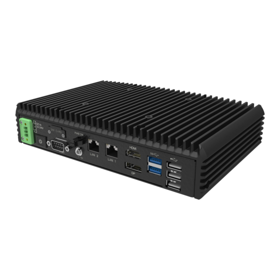
Page 14: 2.2 System Overview
LAN 1 COM1 COM1 LAN2 LAN1 USB 2.0 Power Button 2.2.2 Rear View ANT1 ANT2 ANT4 Normal Sku ANT3 COM2 USB 2.0 COM2 PoE Sku ANT1 ANT2 LAN4 (option) LAN3 LAN4 USB 2.0 LAN3 (option) BS-U830 SERIES USER MANUAL Page: 2-3... -
Page 15: Top View
Chapter 2 Getting Started 2.2.3 Top View Unit: mm 217.50 C.L.75 (VESA) Normal Sku 217.50 C.L.75 (VESA) PoE Sku BS-U830 SERIES USER MANUAL Page: 2-4... -
Page 16: Side View
Chapter 2 Getting Started 2.2.4 Side View Unit: mm Normal Sku PoE Sku BS-U830 SERIES USER MANUAL Page: 2-5... -
Page 17: Bottom View
Chapter 2 Getting Started 2.2.5 Bottom View Normal Sku PoE Sku BS-U830 SERIES USER MANUAL Page: 2-6... -
Page 18: System Specifications
COM1:RS232/422/485, support 5V/12V by jumper Serial Port selection SIM Slot 1 x Micro SIM slot Power On / Off 1 x Power Button with Power LED Power Input 3-pin DC In terminal block (lockable) BS-U830 SERIES USER MANUAL Page: 2-7... - Page 19 HDD: -40°C ~40°C (-40°F~104°F) for Atom SKU Operating Temp. SSD: 0°C ~50°C (32°F~122°F) for other SKUs HDD: 0°C ~40°C (32°F~104°F) for other SKUs -40°C ~85°C (-40°F~185°F) Storage Temp. 20%~ 90% Humidity BS-U830 SERIES USER MANUAL Page: 2-8...
-
Page 20: Safety Precautions
Avoid direct sunlight exposure for a long period of time (for example, in a closed car in summer time. Also avoid the system from any heating device.). Or do not use BS-U830 when it has been left outdoors in a cold winter day. •... -
Page 21: System Configuration
The following topics are included: • System External I/O Ports Diagram • Function Buttons and I/O Ports • Main Board Component Locations & Jumper Settings • Setting Jumpers • Setting Main Board Connectors and Jumpers BS-U830 SERIES USER MANUAL Page: 3-1... -
Page 22: 3.1 External System I/O Ports Diagrams
Chapter 3 System Configuration 3.1 External System I/O Ports Diagrams 3.1.1 Rear I/O Ports Diagrams Normal Sku ANT1 ANT2 ANT4 ANT3 COM2 USB 2.0 COM2 PoE Sku ANT1 ANT2 LAN4 (option) LAN3 LAN4 USB 2.0 LAN3 (option) BS-U830 SERIES USER MANUAL Page: 3-2... -
Page 23: Jumper & Connector Quick Reference Table
HD Audio Connector JAUDIO1 Mini PCI Express Slot M_PCIE1 LVDS Inverter Connector JINV1 LVDS Connector LVDS1 M.2 Wi-Fi Express Slot M2_E1 M.2 SSD Express Slot M2_M1 Serial ATA (SATA) 3.0 connector SATA1 HDD Power Connector JHD_PWR1 BS-U830 SERIES USER MANUAL Page: 3-2... - Page 24 Chapter 3 System Configuration CONNECTOR Description NAME RTC Connector JBAT1 Power LED Connector JLED1 Power Button Connector JBTN1 BS-U830 SERIES USER MANUAL Page: 3-3...
-
Page 25: 3.3 Component Locations Of System Main Board
Make sure to ground yourself to prevent static charge while you are working on the connectors and jumpers. Use a grounding wrist strap and place all electronic components in any static-shielded devices. BS-U830 SERIES USER MANUAL Page: 3-4... -
Page 26: Jumper Setting Of Main Board Be-U830
USB1 (DP & HDMI) JCOMS1 JBAT1 JCOMS1 JBTN1 JSPI JP_USB1 PWR2 SO-DIMM1 JDIO2 JP_COM1 JLPC1 JDIO1 JP_LPC1 M_PCIE1 JCOM2 M.2 SSD JCOM1 JUSB1 JAUDIO1 M2_M1 M.2 Wi-Fi JP_VDD1 SATA1 JHD_PWR1 M2_E1 JINV1 LVDS1 JUSB2 BS-U830 SERIES USER MANUAL Page: 3-5... - Page 27 USB1 (DP & HDMI) JBAT1 JCOMS1 JBTN1 JSPI JP_USB1 PWR2 SO-DIMM1 JDIO2 JP_COM1 JP_COM1 JLPC1 JDIO1 JP_LPC1 M_PCIE1 JCOM2 M.2 SSD JCOM1 JUSB1 JAUDIO1 M2_M1 M.2 Wi-Fi JP_VDD1 SATA1 JHD_PWR1 M2_E1 JINV1 LVDS1 JUSB2 BS-U830 SERIES USER MANUAL Page: 3-6...
- Page 28 USB1 (DP & HDMI) JBAT1 JCOMS1 JBTN1 JSPI JP_USB1 JP_USB1 PWR2 SO-DIMM1 JDIO2 JP_COM1 JLPC1 JDIO1 JP_LPC1 M_PCIE1 JCOM2 M.2 SSD JCOM1 JUSB1 JAUDIO1 M2_M1 M.2 Wi-Fi JP_VDD1 SATA1 JHD_PWR1 M2_E1 JINV1 JUSB2 LVDS1 BS-U830 SERIES USER MANUAL Page: 3-7...
- Page 29 USB1 (DP & HDMI) JBAT1 JCOMS1 JBTN1 JSPI JP_USB1 PWR2 SO-DIMM1 JDIO2 JP_COM1 JLPC1 JP_LPC1 JDIO1 M_PCIE1 JCOM2 M.2 SSD JCOM1 JUSB1 JAUDIO1 M2_M1 M.2 Wi-Fi JP_VDD1 SATA1 JHD_PWR1 M2_E1 JINV1 JUSB2 LVDS1 JP_VDD1 BS-U830 SERIES USER MANUAL Page: 3-8...
- Page 30 USB1 (DP & HDMI) JBAT1 JCOMS1 JBTN1 JSPI JP_USB1 PWR2 SO-DIMM1 JDIO2 JP_LPC1 JLPC1 JP_COM1 JDIO1 JP_LPC1 M_PCIE1 JCOM2 M.2 SSD JCOM1 JUSB1 JAUDIO1 M2_M1 M.2 Wi-Fi JP_VDD1 SATA1 JHD_PWR1 M2_E1 JINV1 JUSB2 LVDS1 BS-U830 SERIES USER MANUAL Page: 3-9...
- Page 31 LAN1 USB1 (DP & HDMI) JBAT1 JCOMS1 JBTN1 JSPI JP_USB1 PWR2 SO-DIMM1 JDIO2 JP_COM1 JLPC1 JDIO1 JP_LPC1 M_PCIE1 JCOM2 M.2 SSD JCOM1 JUSB1 JAUDIO1 M2_M1 M.2 Wi-Fi JP_VDD1 SATA1 JHD_PWR1 M2_E1 JINV1 LVDS1 JUSB2 BS-U830 SERIES USER MANUAL Page: 3-10...
- Page 32 LAN1 USB1 (DP & HDMI) JBAT1 JCOMS1 JBTN1 JSPI JP_USB1 PWR2 SO-DIMM1 JDIO2 JP_COM1 JLPC1 JP_LPC1 JDIO1 M_PCIE1 JCOM2 M.2 SSD JCOM1 JUSB1 JAUDIO1 M2_M1 M.2 Wi-Fi JP_VDD1 SATA1 JHD_PWR1 M2_E1 JUSB2 JINV1 LVDS1 BS-U830 SERIES USER MANUAL Page: 3-11...
-
Page 33: Bottom View Of Main Board Be-U830
Chapter 3 System Configuration 3.3.3 Bottom View of Main Board BE-U830 SIM1 BS-U830 SERIES USER MANUAL Page: 3-12... -
Page 34: How To Set Jumpers
PIN1 & PIN2 to create one setting by shorting. You can either connect PIN2 & PIN3 to create another setting. The same jumper diagrams are applied all through this manual. The figure below illustrates what the jumper diagrams look and what they represent. BS-U830 SERIES USER MANUAL Page: 3-13... - Page 35 Jumper Block looks like this Jumper Settings 2 pin Jumper close(enabled) Looks like this 3 pin Jumper 2-3 pin close(enabled) Looks like this Jumper Block 1-2 pin close(enabled) Looks like this BS-U830 SERIES USER MANUAL Page: 3-14...
-
Page 36: I/O Ports
ACTION ASSIGNMENT Press Release PWRBTN Power Button 3.5.2 DC In 12/24V Port Location: DC In 12/24V Description: Supports DC 12V /24V power input (3-Pin lockable terminal block) (front I/O) ASSIGNMENT +12V DC In 12/24V BS-U830 SERIES USER MANUAL Page: 3-15... -
Page 37: Com1 Port (Com1)
Description: COM1 (RS-232) Connector Pin Assignment (front I/O) ASSIGNMENT ASSIGNMENT DCD# DSR# RTS# CTS# DTR# COM1 3.5.4 COM2 Port (COM2) Port Location: COM2 (D-Sub) Description: COM2 (RS-232) Connector Pin Assignment (rear I/O) ASSIGNMENT ASSIGNMENT DCD# DSR# RTS# CTS# DTR# COM2 BS-U830 SERIES USER MANUAL Page: 3-16... -
Page 38: Dual Lan Ports (Lan1, Lan2)
Right Side LED Green Color On 2500 LAN Speed Indicator Orange Color On 1000 LAN Speed Indicator 10/100 or No LAN connected Left Side LED Yellow Color Blinking LAN Message Active No LAN Message Active BS-U830 SERIES USER MANUAL Page: 3-17... -
Page 39: Dual Lan Ports (Lan3, Lan4) (Option)
Right Side LED Green Color On 2500 LAN Speed Indicator Orange Color On 1000 LAN Speed Indicator 10/100 or No LAN connected Left Side LED Yellow Color Blinking LAN Message Active No LAN Message Active BS-U830 SERIES USER MANUAL Page: 3-18... -
Page 40: X 1 Usb 2.0 Ports (Usb2)
3 x 1 USB 2.0 Ports (USB2) Connector Location: USB2 Description: USB 2.0 Type A Ports x 3 (front I/O) USB 2.0 signals ASSIGNMENT VCC5_USB23 USB2_P2_DN USB2_P2_DP VCC5_USB23 USB2_P3_DN USB2_P3_DP VCC5_USB23 USB2_P4_DN USB2_P4_PN USB2 BS-U830 SERIES USER MANUAL Page: 3-19... -
Page 41: Dual Usb 3.0 Ports (Usb1)
Dual USB 3.0 Ports (USB1) Connector Location: USB1 Description: USB 3.0 Type A Ports (front I/O) USB 3.0 ASSIGNMENT ASSIGNMENT VCC5_USB1 VCC5_USB1 USB2_P1_DN USB2_P0_DN USB2_P1_DP USB2_P0_DP USB3_RXN1 USB3_RXN0 USB3_RXP1 USB3_RXP0 USB1 (USB3.0) USB3_TXN1 USB3_TXN0 USB3_TXP1 USB3_TXP0 BS-U830 SERIES USER MANUAL Page: 3-20... -
Page 42: Dual Usb 2.0 Port (Usb3)
Chapter 3 System Configuration 3.5.9 Dual USB 2.0 Port (USB3) Port Location: USB3 (rear I/O) Description: Dual USB 2.0 Port (Type A) USB 2.0 connector signals: ASSIGNMENT ASSIGNMENT USBPN USBPN USBPP USBPP USB3 BS-U830 SERIES USER MANUAL Page: 3-21... -
Page 43: Display Port (Dp) Port Connector (Dp)
Chapter 3 System Configuration 3.5.10 Display Port (DP) Port Connector (DP) Connector Location: DP Description: DisplayPort Connector (DP) (front I/O) DP signals: ASSIGNMENT ASSIGNMENT DP_TX0_DP DP_TX0_DN DP_TX1_DP DP_TX1_DN DP_TX2_DP DP_TX2_DN_C DP_TX3_DP_C DP_TX3_DN DP_AUX_ENJ DP_AUX_P DP_AUX_N HPD_DP V3P3_DPPWR BS-U830 SERIES USER MANUAL Page: 3-22... -
Page 44: Hdmi Connector (Hdmi)
Chapter 3 System Configuration 3.5.11 HDMI Connector (HDMI) Connector Location: HDMI Description: HDMI Port Connector (HDMI) (front I/O) HDMI ASSIGNMENT ASSIGNMENT HDMI_P2 HDMI_N2 HDMI_P1 HDMI_N1 HDMI_P0 HDMI_N0 HDMI_CLKP HDMI_CLKN HDMI_SCL HDMI_SDA V5P0_HDMI HDMI_HPD BS-U830 SERIES USER MANUAL Page: 3-23... -
Page 45: Digital Input/Output Connector (Dio)
Description: System 16 pins terminal block DIO Port (rear I/O) ASSIGNMENT 1 2 3 4 5 6 7 8 9 101112 13141516 DIN1 DIN2 DIN3 DIN4 DIN5 DIN6 DIN7 DIN8 DOUT1 DOUT2 DOUT3 DOUT4 DOUT5 DOUT6 DOUT7 DOUT8 BS-U830 SERIES USER MANUAL Page: 3-24... -
Page 46: Setting Connectors And Jumpers
Setting Connectors and Jumpers 3.6.1 COM1 and COM2 Connector (JCOM1, JCOM2) Connector Location: JCOM1 and JCOM2 Description: COM1 and COM2 Connector ASSIGNMENT ASSIGNMENT COM1/2_DCD COM1/2_DSR COM1/2_RX COM1/2_RTS COM1/2_TX COM1/2_CTS COM1/2_DTR COM1/2_DCOUT JCOM1 / JCOM2 BS-U830 SERIES USER MANUAL Page: 3-25... -
Page 47: Internal Usb 2.0 Pin Headers (Jusb1)
Description: 2 x Internal USB 2.0 Pin Headers ASSIGNMENT ASSIGNMENT VCC5_USB56 VCC5_USB56 USB2_P5_DN USB2_P6_DN USB2_P5_DP USB2_P6_DP JUSB1 Internal USB 2.0 Wafer (JUSB2) 3.6.3 Connector Location: JUSB2 Description: Internal USB 2.0 Wafer ASSIGNMENT VCC5_USB7 USB2_P7_DN USB2_P7_DP JUSB2 BS-U830 SERIES USER MANUAL Page: 3-26... -
Page 48: Digital Input / Output Connectors (Jdio1, Jdio2)
Description: Digital Input / Output Connector ASSIGNMENT ASSIGNMENT V5P0_PWROUT V5P0_PWROUT DIN_0 DOUT_0 DIN_1 DOUT_1 DIN_2 DOUT_2 JDIO1 Connector Location: JDIO2 Description: Digital Input / Output Connector ASSIGNMENT ASSIGNMENT DIN_3 DOUT_3 DIN_4 DOUT_4 DIN_5 DOUT_5 DIN_6 DOUT_6 DIN_7 DOUT_7 JDIO2 BS-U830 SERIES USER MANUAL Page: 3-27... -
Page 49: Hd Audio Connector (Jaudio1)
Chapter 3 System Configuration 3.6.5 HD Audio Connector (JAUDIO1) Connector Location: JAUDIO1 Description: HD Audio Connector ASSIGNMENT ASSIGNMENT HD_MIC-L HD_MIC1-R HD_GND HD_GND HD_LINE-IN-L HD_LINE-IN-R HD_GND HD_GND LINE-OUT-L LINE-OUT-R JAUDIO1 BS-U830 SERIES USER MANUAL Page: 3-28... -
Page 50: Mini Pci Express Slot (M_Pcie1)
Connector Location: M_PCIE1 Description: Mini PCI Express Slot ASSIGNMENT ASSIGNMENT WAKE_N V3P3A VCC1_5_M_PCIE PCIE_CLKREQ2_N M_PCIE_CLKN M_PCIE_CLKP SIM1_C8 SIM1_C4 BUF_PLT_RST_N PCIE_P3_RXN V3P3A PCIE_P3_RXP M_PCIE1 VCC1_5_M_PCIE SMB_CLK PCIE_P3_TXN SMB_DATA PCIE_P3_TXP USB2_P8_DN USB2_P8_DP V3P3A V3P3A VCC1_5_M_PCIE V3P3A BS-U830 SERIES USER MANUAL Page: 3-29... -
Page 51: Micro Sim Card Socket (Sim1)
Chapter 3 System Configuration 3.6.7 Micro SIM Card Socket (SIM1) Connector Location: SIM1 Description: Micro SIM Push/Push type (located on the bottom side of the main board) ASSIGNMENT SIM1_PWR ATTEND SIM1_RESET SIM1_VPP SIM1_CLK SIM1_DATA SIM1_C4 SIM1_C8 SIM1 BS-U830 SERIES USER MANUAL Page: 3-30... -
Page 52: Lvds Inverter Connector (Jinv1)
Chapter 3 System Configuration 3.6.8 LVDS Inverter Connector (JINV1) Connector Location: JINV1 Description: LVDS Inverter Connector ASSIGNMENT VCC12 VCC12 JINV1 LVDS_BKLCTL LVDS_BKLTEN BS-U830 SERIES USER MANUAL Page: 3-31... -
Page 53: Lvds Connector (Lvds1)
LVDS Connector (LVDS1) Connector Location: LVDS1 Description: LVDS Inverter Connector LVDS1 ASSIGNMENT ASSIGNMENT LVDS_VCC LVDS_CLKB_DN LVDS_CLKB_DP LVDS_B2_DN LVDS_B2_DP LVDS_B1_DN LVDS_B1_DP LVDS_B3_DP LVDS_B3_DN LVDS_B0_DP LVDS_B0_DN LVDS_CLKA_DP LVDS_CLKA_DN LVDS_A2_DP LVDS_A2_DN LVDS_A1_DP LVDS_A1_DN LVDS_A0_DP LVDS_A0_DN LVDS_A3_DP LVDS_A3_DN LVDS_VCC LVDS_VCC BS-U830 SERIES USER MANUAL Page: 3-32... -
Page 54: Wi-Fi Express Slot (M2_E1)
Chapter 3 System Configuration 3.6.10 M.2 Wi-Fi Express Slot (M2_E1) Connector Location: M2_E1 Description: M.2 Wi-Fi Express Slot M2_E1 ASSIGNMENT ASSIGNMENT V3P3 USB2_P9_DP V3P3 USB2_P9_DN PCIE_P6_TXP PCIE_P6_TXN PCIE_P6_RXP PCIE_P6_RXN M2_E_CLKP M2_E_CLKN BUF_PLT_RST_N PCIE_CLKREQ1_N M2_E_BT_WISABLE2 BS-U830 SERIES USER MANUAL Page: 3-33... - Page 55 Chapter 3 System Configuration ASSIGNMENT ASSIGNMENT WAKE_N M2_E_WLAN_WISABLE1 V3P3 V3P3 BS-U830 SERIES USER MANUAL Page: 3-34...
-
Page 56: Ssd Express Slot (M2_M1)
Chapter 3 System Configuration 3.6.11 M.2 SSD Express Slot (M2_M1) Connector Location: M2_M1 Description: M.2 SSD KEY M Slot M2_M1 ASSIGNMENT ASSIGNMENT V3P3 V3P3 V3P3 V3P3 V3P3 V3P3 PCIE_P5_RXN PCIE_P5_RXP PCIE_P5_TXN PCIE_P5_TXP PCIE_P4_RXN PCIE_P4_RXP BS-U830 SERIES USER MANUAL Page: 3-35... - Page 57 Chapter 3 System Configuration ASSIGNMENT ASSIGNMENT PCIE_P4_TXN PCIE_P4_TXP BUF_PLT_RST_N PCIE_CLKREQ0_N M2_M_CLKN WAKE_N M2_M_CLKP V3P3 V3P3 V3P3 BS-U830 SERIES USER MANUAL Page: 3-36...
- Page 58 Chapter 3 System Configuration 3.6.12 SATA 3.0 & HDD Power Connectors (SATA1, JHD_PWR1) Connector Location: SATA1 Description: Serial ATA 3.0 connector ASSIGNMENT SATA_TXP0 SATA_TXN0 SATA1 SATA_RXN0 SATA_RXP0 Connector Location: JHD_PWR1 Description: HDD Power Connector ASSIGNMENT V5P0 JHD_PWR1 BS-U830 SERIES USER MANUAL Page: 3-37...
-
Page 59: Rtc Connector (Jbat1)
Description: RTC Connector ASSIGNMENT JBAT1 3.6.14 Power LED Connector (JLED1) Connector Location: JLED1 Description: Power LED Connector ASSIGNMENT JLED_V5P0 JLED1 3.6.15 Power Button Connector (JBTN1) Connector Location: JBTN1 Description: Power Button Connector ASSIGNMENT PWRBTN_N JBTN1 BS-U830 SERIES USER MANUAL Page: 3-38... -
Page 60: Com1 Port Voltage Selection (Jp_Com1)
Chapter 3 System Configuration 3.6.16 COM1 Port Voltage Selection (JP_COM1) Jumper Location: JP_COM1 Description: COM1 Port Voltage Selection Selection Jumper Setting Jumper Illustration Open (Default Setting) JP_COM1 JP_COM1 JP_COM1 BS-U830 SERIES USER MANUAL Page: 3-39... -
Page 61: Usb1 Port Power Selection (Jp_Usb1)
Chapter 3 System Configuration 3.6.17 USB1 Port Power Selection (JP_USB1) Jumper Location: JP_USB1 Description: USB1 Port Power Selection Selection Jumper Setting Jumper Illustration S5 , USB Power=0V (Default Setting) JP_USB1 USB Power=5V JP_USB1 BS-U830 SERIES USER MANUAL Page: 3-40... -
Page 62: Lvds Voltage Selection (Jp_Vdd1)
Chapter 3 System Configuration 3.6.18 LVDS Voltage Selection (JP_VDD1) Jumper Location: JP_VDD1 Description: LVDS Voltage Selection Selection Jumper Setting Jumper Illustration 3.3V (Default Setting) JP_VDD1 JP_VDD1 BS-U830 SERIES USER MANUAL Page: 3-41... -
Page 63: Low Pin Count Selection (Jp_Lpc1)
Chapter 3 System Configuration 3.6.19 Low Pin Count Selection (JP_LPC1) Jumper Location: JP_LPC1 Description: Low Pin Count Selection Selection Jumper Setting Jumper Illustration Open 80 Port (Default Setting) JP_LPC1 LPC Device JP_LPC1 BS-U830 SERIES USER MANUAL Page: 3-42... -
Page 64: Lvds Sequence Control Selection (Jp1)
Chapter 3 System Configuration 3.6.20 LVDS Sequence Control Selection (JP1) Connector Location: JP1 Description: LVDS Sequence Control Selection Selection Jumper Setting Jumper Illustration BKLTCTL from (Default Setting) BKLTCTL from PTN3460I BKLTEN from (Default Setting) BKLTEN from PTN3460I BS-U830 SERIES USER MANUAL Page: 3-43... -
Page 65: Lvds Backlight Control Selection (Jp7)
Chapter 3 System Configuration 3.6.21 LVDS Backlight Control Selection (JP7) Jumper Location: JP7 Description: LVDS Backlight Control Selection Selection Jumper Setting Jumper Illustration 3.3V (Default Setting) BS-U830 SERIES USER MANUAL Page: 3-44... -
Page 66: Clear Cmos Data Selection (Jcoms1)
Step 4. Power on the PC and the PC will then auto-reboot for once in order to set SoC’s register. Step 5. Done! Selection Jumper Setting Jumper Illustration Open Normal (Default Setting) JCOMS1 Clear CMOS* JCOMS1 Note: Please make sure the main power is off before you clear CMOS data. BS-U830 SERIES USER MANUAL Page: 3-45... -
Page 67: Software Utilities
® • Installing Intel Chipset Software Installation Utility • Installing Graphics Driver Utility • Installing LAN Driver Utility • Installing Sound Driver Utility ® • Installing Intel Management Engine Components Driver Installer BS-U830 SERIES USER MANUAL Page: 4-1... - Page 68 Chapter 4 Software Utilities Introduction Enclosed with the BS-U830 Series package is our driver utilities contained in a DVD-ROM disk. Refer to the following table for driver locations: Filename (Assume that Purpose DVD- ROM drive is D :) D: \Driver\Platform\1_Main ®...
-
Page 69: Introduction
The utility pack is to be installed only for Windows 10 (64-bit), and it should be installed immediately after the OS installation is finished. Please follow the steps below: Connect the USB DVD-ROM device to BS-U830 and insert the driver disk. Enter the Main Chip folder where the Chipset driver is located. -
Page 70: Installing Graphics Driver Utility
Chapter 4 Software Utilities Installing Graphics Driver Utility To install the Graphics driver utility, follow the steps below: Connect the USB DVD-ROM device to BS-U830 and insert the driver disk. Enter the Graphics folder where the driver is located. Click the Installer.exe file for driver installation. -
Page 71: Installing Lan Driver Utility
Enhanced with LAN function, BS-U830 supports various network adapters. To install the LAN Driver, follow the steps below: Connect the USB DVD-ROM device to BS-U830 and insert the driver disk. Enter the LAN Chip folder where the driver is located. -
Page 72: Installing Sound Driver Utility
Chapter 4 Software Utilities Installing Sound Driver Utility To install the Sound Driver, follow the steps below: Connect the USB DVD-ROM device to BS-U830 and insert the driver disk. Open the Sound folder where the driver is located. Click the Setup.exe file for driver installation. -
Page 73: Installing Intel ® Management Engine Components Driver Installer
® Installation Instructions for Intel Management Engine Components Driver Installer Connect the USB DVD-ROM device to BS-U830 and insert the driver disk. Enter the ME folder where the driver is located. Click SetupME.exe file for ME driver installation. Follow the on-screen instructions to complete the installation. -
Page 74: Bios Setup
The BIOS Setup Utilities consist of the following menu items: Main Menu • Advanced Menu • Chipset Menu • Security Menu • Boot Menu • Save & Exit Menu • BS-U830 SERIES USER MANUAL Page: 5-1... -
Page 75: Introduction
BS-U830 SERIES USER MANUAL Page: 5-2... -
Page 76: Accessing Setup Utility
POST message will be displayed: Figure 5-2. POST Screen with AMI Logo Press <Del> or <Esc> to access the Setup Utility program and the Main menu of the Aptio Setup Utility will appear on the screen as below: BS-U830 SERIES USER MANUAL Page: 5-3... - Page 77 English. You may use <↑> or <↓> key to select among the items and press <Enter> to confirm and enter the sub-menu. The following table provides the list of the navigation keys that you can use while operating the BIOS setup menu. BS-U830 SERIES USER MANUAL Page: 5-4...
- Page 78 Load the previous configuration values. <F3> Load the default configuration values. <F4> Save the current values and exit the BIOS setup menu. <Esc> Close the sub-menu. Trigger the confirmation to exit BIOS setup menu. BS-U830 SERIES USER MANUAL Page: 5-5...
-
Page 79: Main
Name No changeable options Displays the name of the PCH. PCH SKU No changeable options Displays the SKU for the PCH. Stepping No changeable options Displays the stepping of the PCH. BS-U830 SERIES USER MANUAL Page: 5-6... - Page 80 The “Day” is automatically changed. System Time Hour, minute, second Sets the system time. The format is [Hour: Minute: Second]. Users can directly enter values or use <+> or <-> arrow keys to increase/decrease it. BS-U830 SERIES USER MANUAL Page: 5-7...
-
Page 81: Advanced
S5 RTC Wake Settings Sub-Menu S5 RTC Wake Parameters. PTN3460 EDID Configuration Sub-Menu PTN3460 EDID Settings. USB Configuration Sub-Menu USB Configuration Parameters. Network Stack Configuration Sub-Menu Network Stack Settings. NVMe Configuration Sub-Menu NVMe Device Options Settings. BS-U830 SERIES USER MANUAL Page: 5-8... -
Page 82: Advanced - Cpu Configuration
SMX (Secure Mode No changeable options Secure Mode extensions support. Extensions) / TXT When enabled, VMM can utilize the Intel (VMX) Virtualization - Disabled additional hardware capabilities Technology - Enabled (default) provided by Vanderpool Technology. BS-U830 SERIES USER MANUAL Page: 5-9... -
Page 83: Advanced - Pch-Fw Configuration
Description/Purpose ME Firmware Version No changeable options Displays the ME Firmware Version. ME Firmware Mode No changeable options Displays the ME Firmware Mode. ME Firmware SKU No changeable options Displays the ME Firmware SKU. BS-U830 SERIES USER MANUAL Page: 5-10... -
Page 84: Advanced - Acpi Settings
- Suspend Disabled Selects the highest ACPI sleep state the ACPI Sleep State - S3 (Suspend to RAM) system will enter when the SUSPEND (Default) button is pressed. BS-U830 SERIES USER MANUAL Page: 5-11... -
Page 85: Advanced - F81967 Super Io Configuration
Advanced > F81967 Super IO Configuration F81967 Super IO Configuration Screen BIOS Setting Options Description/Purpose Serial Port 1 Configuration Sub-Menu Sets Parameters of Serial Port 1 (COM1). Serial Port 2 Configuration Sub-Menu Sets Parameters of Serial Port 2 (COM2). BS-U830 SERIES USER MANUAL Page: 5-12... -
Page 86: F81967 Super Io Configuration - Serial Port 1 Configuration
- IO=3F8h; IRQ=3,4,5,6,7,9,10,11.12; Selects IRQ and I/O resource Change Settings - IO=2F8h; IRQ=3,4,5,6,7,9,10,11,12; for Serial Port 1. - IO=3E8h; IRQ=3,4,5,6,7,9,10,11,12; - IO=2E8h; IRQ=3,4,5,6,7,9,10,11,12; - RS-232 (Default) Mode - RS-422 Selects COM mode. - RS-485 BS-U830 SERIES USER MANUAL Page: 5-13... -
Page 87: F81967 Super Io Configuration - Serial Port 2 Configuration
Selects IRQ and I/O resource - IO=2F8h; IRQ=3; for Serial Port 2. - IO=3F8h; IRQ=3,4,5,6,7,9,10,11.12; Change Settings - IO=2F8h; IRQ=3,4,5,6,7,9,10,11,12; - IO=3E8h; IRQ=3,4,5,6,7,9,10,11,12; - IO=2E8h; IRQ=3,4,5,6,7,9,10,11,12; - RS-232 (Default) Mode - RS-422 Selects COM mode. - RS-485 BS-U830 SERIES USER MANUAL Page: 5-14... -
Page 88: Advanced - Hardware Monitor
Displays the voltage level of VDDQ VDDQ No changeable options in supply. Displays the voltage level of VCC3V VCC3V No changeable options in supply. Displays the voltage level of VSB3V VSB3V No changeable options in supply. BS-U830 SERIES USER MANUAL Page: 5-15... -
Page 89: Advanced - F81967 Watchdog
F81967 Watchdog Screen BIOS Setting Options Description/Purpose - Enabled Super I/O Watchdog timer settings Enable Watchdog - Disabled (Default) enabled/disabled. Numeric Watchdog Timer Count The number of count for Timer. (from 10 to 255) BS-U830 SERIES USER MANUAL Page: 5-16... -
Page 90: Advanced - S5 Rtc Wake Settings
Enters 0-59 to set the wake-up Wake up second Numeric (from 0 to 59) second. Enters 1-5 to set the increased Wake up minute increase Numeric (from 1 to 5) minute(s) for dynamic wake-up time. BS-U830 SERIES USER MANUAL Page: 5-17... -
Page 91: Advanced - Ptn3460 Edid Configuration
- 2-G150XNE-L03 (15\" 1024x768) configuration table in EDID Selection - 3-G170ETN01.0 (17\" 1280x1024 Dual) SRAM, select the EDID for - 4-G156XW01.3 (15.6\" 1366x768) attached LVDS panel. - 5-G190ETN01.2 (19\" 1280x1024 Dual) - 6-G238HAN01.1 (23.8\" 1920x1080 Dual) BS-U830 SERIES USER MANUAL Page: 5-18... -
Page 92: Advanced - Usb Configuration
Optical drives MASS STORAGE - Forced FDD are emulated as 'CD-ROM'. Drives DEVICES: [drive(s)] - Hard Disk with no media will be emulated - CD-ROM according to a drive type. BS-U830 SERIES USER MANUAL Page: 5-19... -
Page 93: Advanced - Network Stack Configuration
Enables / Disables UEFI Network Network Stack - Enabled Stack. Enables / Disables Ipv4 PXE boot - Disabled (Default) Ipv4 PXE Support support. If disabled, Ipv4 PXE boot - Enabled support will not be available. BS-U830 SERIES USER MANUAL Page: 5-20... -
Page 94: Advanced - Nvme Configuration
Numeric (from 1 to 50) will be checked. 5.4.11 Advanced – NVMe Configuration Menu Path Advanced > NVMe Configuration NVMe Configuration Screen BIOS Setting Options Description/Purpose NVMe Configuration No changeable options Displays NVMe device BS-U830 SERIES USER MANUAL Page: 5-21... -
Page 95: Chipset
This menu allows users to configure advanced Chipset settings such as System Agent (SA) and PCH-IO configuration parameters. Chipset Screen BIOS Setting Options Description/Purpose System Agent (SA) Configuration Sub-Menu System Agent (SA) Parameters. PCH-IO Configuration Sub-Menu PCH Parameters. BS-U830 SERIES USER MANUAL Page: 5-22... -
Page 96: Chipset - System Agent (Sa) Configuration
Chipset – System Agent (SA) Configuration Menu Path Chipset > System Agent (SA) Configuration System Agent (SA) Configuration Screen BIOS Setting Options Description/Purpose Memory Configuration Sub-Menu Memory Configuration. - Disabled VT-d Enables or Disables VT-d function. - Enabled (Default) BS-U830 SERIES USER MANUAL Page: 5-23... -
Page 97: System Agent (Sa) Configuration - Memory Configuration
Displays the Number of Ranks in the Number of Ranks No changeable options slot. Displays the DIMM Manufacturer Manufacturer No changeable options name. Enables/Disables In-Band ECC. - Enabled (Default) In-Band ECC (For Embedded/Industrial Processor - Disabled SKU only) BS-U830 SERIES USER MANUAL Page: 5-24... - Page 98 1: Makes all requests non protected Mode and ignore range checks, - 2 (Default) 2: Makes all requests protected and ignore range checks - Enabled Enables/Disables Error Injection. In-Band ECC Error Injection - Disabled (Default) (For test purpose) BS-U830 SERIES USER MANUAL Page: 5-25...
-
Page 99: Chipset - Pch-Io Configuratioin
- Power On Restore AC Power Loss power is re-applied following a - Power Off (Default) power failure (G3 state). - Disabled (Default) Enables or Disables LPC Debug 80 LPC Debug 80 Port - Enabled Port. BS-U830 SERIES USER MANUAL Page: 5-26... -
Page 100: Pch-Io Configuration - Pci Express Configuration
PCI Express Root Port 4 Sub-Menu PCI Express Mini-PCIe settings. (Mini-PCIe) PCI Express Root Port 5 Sub-Menu PCI Express M.2 M_KEY settings. (M.2 M_KEY) PCI Express Root Port 7 Sub-Menu PCI Express M.2 E_KEY settings. (M.2 E_KEY) BS-U830 SERIES USER MANUAL Page: 5-27... -
Page 101: Pch-Io Configuration - Pci Express Configuration - Pci Express
Options Description/Purpose - Disabled Enables or Disables the PCI Express PCI Express Root Port 2 - Enabled (Default) Root Port. - Auto (Default) - Gen1 PCIe Speed Configures PCIe Speed. - Gen2 - Gen3 BS-U830 SERIES USER MANUAL Page: 5-28... -
Page 102: Pch-Io Configuration - Pci Express Configuration - Pci Express
Options Description/Purpose - Disabled Enables or Disables the PCI Express PCI Express Root Port 3 - Enabled (Default) Root Port. - Auto (Default) - Gen1 PCIe Speed Configures PCIe Speed. - Gen2 - Gen3 BS-U830 SERIES USER MANUAL Page: 5-29... -
Page 103: Pch-Io Configuration - Pci Express Configuration - Pci Express
Options Description/Purpose - Disabled Enables or Disables the PCI Express PCI Express Root Port 4 - Enabled (Default) Root Port. - Auto (Default) - Gen1 PCIe Speed Configures PCIe Speed. - Gen2 - Gen3 BS-U830 SERIES USER MANUAL Page: 5-30... -
Page 104: Pch-Io Configuration - Pci Express Configuration - Pci Express
Options Description/Purpose - Disabled Enables or Disables the PCI Express PCI Express Root Port 5 - Enabled (Default) Root Port. - Auto (Default) - Gen1 PCIe Speed Configures PCIe Speed. - Gen2 - Gen3 BS-U830 SERIES USER MANUAL Page: 5-31... -
Page 105: Pch-Io Configuration - Pci Express Configuration - Pci Express
Options Description/Purpose - Disabled Enables or Disables the PCI Express PCI Express Root Port 7 - Enabled (Default) Root Port. - Auto (Default) - Gen1 PCIe Speed Configures PCIe Speed. - Gen2 - Gen3 BS-U830 SERIES USER MANUAL Page: 5-32... -
Page 106: Pch-Io Configuration - Sata Configuration
Enabled (Default) SATA Controller(s) Enables or Disables SATA Device. - Disabled Determines how SATA controller(s) SATA Mode Selection - AHCI (Default) operate. Serial ATA Port 0 No changeable options Displays the SATA device’s name. BS-U830 SERIES USER MANUAL Page: 5-33... -
Page 107: Security
Setup utility. Security Screen BIOS Setting Options Description/Purpose Password can be 3-20 Specifies the administrator Administrator Password alphanumeric characters. password. Password can be 3-20 User Password Specifies the user password. alphanumeric characters. BS-U830 SERIES USER MANUAL Page: 5-34... - Page 108 <Enter>, and the password dialog entry box appears. Select the configured Administrator Password or User Password that you want to delete. Leave the dialog box blank and press <Enter>. Press <Enter> again when the password confirmation box appears. BS-U830 SERIES USER MANUAL Page: 5-35...
-
Page 109: Boot
Enables or Disables Quiet Boot Quiet Boot - Enabled options. - [Drive(s)] Boot Option #1~#n Sets the system boot order. - Disabled - Disabled (Default) Enables or Disables Fast Boot Fast Boot - Enabled options. BS-U830 SERIES USER MANUAL Page: 5-36... -
Page 110: Save & Exit
Discard Changes and Reset to discard any changes you have made and restore the factory BIOS defaults. Load User Defaults You may simply press F3 at any time to load the Optimized Values which resets all BIOS settings to the factory defaults. Save & Exit Screen BS-U830 SERIES USER MANUAL Page: 5-37... - Page 111 Saves the changes done so far as User Save as User Defaults No changeable options Defaults. Restores the User Defaults to all the Restore User Defaults No changeable options setup options. Forces to boot from selected Boot Override - [Drive(s)] [drive(s)]. BS-U830 SERIES USER MANUAL Page: 5-38...
-
Page 112: Appendix A System Diagrams
Appendix A System Diagrams This appendix presents the exploded diagrams of the system as well as the part numbers of BS-U830 system for both Normal Sku and PoE Sku. BS-U830 System Exploded Diagram • BS-U830 Heatsink Case Assembly Exploded •... -
Page 113: Bs-U830 System Exploded Diagram (Normal Sku
Appendix A System Diagrams BS-U830 System Exploded Diagram (Normal Sku) BS-U830 SERIES USER MANUAL Page: A-2... - Page 114 See Page A-6 BE-U830 Main PCB BE-U830 BS-U830 Front Bracket (w/Paint)(Black) 20-106-03062492 Flat Head Screw #2 / M3x0.5Px5mm 22-215-30005011 BS-U830 Rear Bracket COM (w/Paint)(Black) 20-106-03064492 BS-U830 BTM Bracket (w/Paint)(Black) 20-106-03061492 Audio Cable (Line-out only) BS-E097_2INCH_HDD_SATA_KIT_ASM_EXP See Page A-8 Thermal Interface Pads, K=3.2,85x60x3mm...
-
Page 115: Bs-U830 System Exploded Diagram (Poe Sku
Appendix A System Diagrams BS-U830 System Exploded Diagram (PoE Sku) BS-U830 SERIES USER MANUAL Page: A-4... - Page 116 BE-U830 Main PCB BE-U830 PoE Module BS-U830 Front Bracket (w/Paint)(Black) 20-106-03062492 Flat Head Screw #2 / M3x0.5Px5mm 22-215-30005011 BS-U830 Rear Bracket (w/Paint) (Black) 20-106-03063492 BS-U830 BTM Bracket (w/Paint) (Black) 20-106-03061492 Audio Cable (Line-out only) BS-E097_2INCH_HDD_SATA_KIT_ASM_EXP See Page A-9 Thermal Interface Pads, K=3.2,85x60x3mm...
-
Page 117: Bs-U830 Heatsink Case Assembly Exploded Diagram (Normal Sku
Appendix A System Diagrams BS-U830 Heatsink Case Assembly Exploded Diagram (Normal Sku) ITEM Description Part No. Q’ty BS-U830 Heatsink Case (Black) 81-002-11841008 (217.5x140.6x46mm) BS-U830 CU CPU Block (98x42x2mm) 81-002-29842001 Flat Head Screw #1 / M2x0.4Px5mm 22-215-20005011 Flat Head Screw#2 / M3x0.5Px5mm... -
Page 118: Bs-U830 Heatsink Case Assembly Exploded Diagram (Poe Sku
Appendix A System Diagrams BS-U830 Heatsink Case Assembly Exploded Diagram (PoE Sku) ITEM Description Part No. Q’ty BS-U830 Heatsink Case (Black) 81-002-11841008 (217.5x140.6x46mm) BS-U830 CU CPU Block (98x42x2mm) 81-002-29842001 Flat Head Screw #1 / M2x0.4Px5mm 22-215-20005011 Flat Head Screw#2 / M3x0.5Px5mm... -
Page 119: Bs-U830 Hdd Module Assembly Exploded Diagram (Normal Sku
Appendix A System Diagrams BS-U830 HDD Module Assembly Exploded Diagram (Normal Sku) ITEM Description Part No. Q’ty BS-U830 HDD Support 20-102-03001492 2.5" SATA HDD/SSD SATA HDD & Power Cable Rubber Washer (OD =Φ9.62mm, 23-680-39580963 ID=Φ3.9mmx5.8T) (Blue) Fillister Head Screw M3x0.5Px4.8mm... -
Page 120: Bs-U830 Hdd Module Assembly Exploded Diagram (Poe Sku
Appendix A System Diagrams BS-U830 HDD Module Assembly Exploded Diagram (PoE Sku) ITEM Description Part No. Q’ty BS-U830 HDD Support 20-102-03001492 2.5" SATA HDD/SSD SATA HDD & Power Cable Rubber Washer (OD =Φ9.62mm, 23-680-39580963 ID=Φ3.9mmx5.8T) (Blue) Fillister Head Screw M3x0.5Px4.8mm... -
Page 121: Bs-U830 Front Case Assembly Exploded Diagram (Normal Sku
Appendix A System Diagrams BS-U830 Front Case Assembly Exploded Diagram (Normal Sku) ITEM Description Part No. Q’ty Flat Head Screw #2 / M4x0.7Px6mm 22-215-40006011 (Black) Rubber Foot (Φ11.1x3.96mm) (Black) 90-004-01400000 BS-U830 SERIES USER MANUAL Page: A-10... -
Page 122: Bs-U830 Front Case Assembly Exploded Diagram (Poe Sku
Appendix A System Diagrams BS-U830 Front Case Assembly Exploded Diagram (PoE Sku) ITEM Description Part No. Q’ty Flat Head Screw #2 / M4x0.7Px6mm 22-215-40006011 (Black) Rubber foot (Φ11.1x3.96mm) (Black) 90-004-01400000 BS-U830 SERIES USER MANUAL Page: A-11... -
Page 123: Bs-U830 Wall Mount Kit Assembly Exploded Diagram (Normal Sku
Appendix A System Diagrams BS-U830 Wall Mount Kit Assembly Exploded Diagram (Normal Sku) ITEM Description Part No. Q’ty Flat Head Screw #2 / M4x0.7Px6mm 22-215-40006011 (Black) BS-E098 Stand (w/Paint)(Black) 20-017-02062405 BS-U830 SERIES USER MANUAL Page: A-12... -
Page 124: Bs-U830 Wall Mount Kit Assembly Exploded Diagram (Poe Sku
Appendix A System Diagrams BS-U830 Wall Mount Kit Assembly Exploded Diagram (PoE Sku) ITEM Description Part No. Q’ty Flat Head Screw #2 / M4x0.7Px6mm 22-215-40006011 (Black) BS-E098 Stand (w/Paint)(Black) 20-017-02062405 BS-U830 SERIES USER MANUAL Page: A-13... -
Page 125: Appendix B Technical Summary
Appendix B Technical Summary This appendix will give you a brief introduction of the allocation maps for BS-U830 resources. The following topics are included: • Block Diagram • Interrupt Map • I/O Map • Memory Map • Configuring WatchDog Timer •... -
Page 126: Block Diagram
SMBUS F75111 USB 2.0 x 4 USB2.0 8IN/8OUT SLM9670 SATA x 1 SATA3.0 COM1 support 5V/12V COM 1 F81439A RS232/422/485 PCI_E x1 F81967AD-I eSPI UART Mini PCI_E (Super IO) COM 2 USB2.0 F81439A RS232/422/485 BS-U830 SERIES USER MANUAL Page: B-2... -
Page 127: Interrupt Map
IRQ 75 Microsoft ACPI-Compliant System IRQ 76 Microsoft ACPI-Compliant System IRQ 77 Microsoft ACPI-Compliant System IRQ 78 Microsoft ACPI-Compliant System IRQ 79 Microsoft ACPI-Compliant System IRQ 80 Microsoft ACPI-Compliant System IRQ 81 Microsoft ACPI-Compliant System BS-U830 SERIES USER MANUAL Page: B-3... - Page 128 IRQ 108 Microsoft ACPI-Compliant System IRQ 109 Microsoft ACPI-Compliant System IRQ 110 Microsoft ACPI-Compliant System IRQ 111 Microsoft ACPI-Compliant System IRQ 112 Microsoft ACPI-Compliant System IRQ 113 Microsoft ACPI-Compliant System IRQ 114 Microsoft ACPI-Compliant System BS-U830 SERIES USER MANUAL Page: B-4...
- Page 129 IRQ 143 Microsoft ACPI-Compliant System IRQ 144 Microsoft ACPI-Compliant System IRQ 145 Microsoft ACPI-Compliant System IRQ 146 Microsoft ACPI-Compliant System IRQ 147 Microsoft ACPI-Compliant System IRQ 148 Microsoft ACPI-Compliant System IRQ 149 Microsoft ACPI-Compliant System BS-U830 SERIES USER MANUAL Page: B-5...
- Page 130 IRQ 176 Microsoft ACPI-Compliant System IRQ 177 Microsoft ACPI-Compliant System IRQ 178 Microsoft ACPI-Compliant System IRQ 179 Microsoft ACPI-Compliant System IRQ 180 Microsoft ACPI-Compliant System IRQ 181 Microsoft ACPI-Compliant System IRQ 182 Microsoft ACPI-Compliant System BS-U830 SERIES USER MANUAL Page: B-6...
- Page 131 IRQ 262 Microsoft ACPI-Compliant System IRQ 263 Microsoft ACPI-Compliant System IRQ 264 Microsoft ACPI-Compliant System IRQ 265 Microsoft ACPI-Compliant System IRQ 266 Microsoft ACPI-Compliant System IRQ 267 Microsoft ACPI-Compliant System IRQ 268 Microsoft ACPI-Compliant System BS-U830 SERIES USER MANUAL Page: B-7...
- Page 132 IRQ 295 Microsoft ACPI-Compliant System IRQ 296 Microsoft ACPI-Compliant System IRQ 297 Microsoft ACPI-Compliant System IRQ 298 Microsoft ACPI-Compliant System IRQ 299 Microsoft ACPI-Compliant System IRQ 300 Microsoft ACPI-Compliant System IRQ 301 Microsoft ACPI-Compliant System BS-U830 SERIES USER MANUAL Page: B-8...
- Page 133 IRQ 330 Microsoft ACPI-Compliant System IRQ 331 Microsoft ACPI-Compliant System IRQ 332 Microsoft ACPI-Compliant System IRQ 333 Microsoft ACPI-Compliant System IRQ 334 Microsoft ACPI-Compliant System IRQ 335 Microsoft ACPI-Compliant System IRQ 336 Microsoft ACPI-Compliant System BS-U830 SERIES USER MANUAL Page: B-9...
- Page 134 IRQ 363 Microsoft ACPI-Compliant System IRQ 364 Microsoft ACPI-Compliant System IRQ 365 Microsoft ACPI-Compliant System IRQ 366 Microsoft ACPI-Compliant System IRQ 367 Microsoft ACPI-Compliant System IRQ 368 Microsoft ACPI-Compliant System IRQ 369 Microsoft ACPI-Compliant System BS-U830 SERIES USER MANUAL Page: B-10...
- Page 135 IRQ 398 Microsoft ACPI-Compliant System IRQ 399 Microsoft ACPI-Compliant System IRQ 400 Microsoft ACPI-Compliant System IRQ 401 Microsoft ACPI-Compliant System IRQ 402 Microsoft ACPI-Compliant System IRQ 403 Microsoft ACPI-Compliant System IRQ 404 Microsoft ACPI-Compliant System BS-U830 SERIES USER MANUAL Page: B-11...
- Page 136 IRQ 431 Microsoft ACPI-Compliant System IRQ 432 Microsoft ACPI-Compliant System IRQ 433 Microsoft ACPI-Compliant System IRQ 434 Microsoft ACPI-Compliant System IRQ 435 Microsoft ACPI-Compliant System IRQ 436 Microsoft ACPI-Compliant System IRQ 437 Microsoft ACPI-Compliant System BS-U830 SERIES USER MANUAL Page: B-12...
- Page 137 IRQ 466 Microsoft ACPI-Compliant System IRQ 467 Microsoft ACPI-Compliant System IRQ 468 Microsoft ACPI-Compliant System IRQ 469 Microsoft ACPI-Compliant System IRQ 470 Microsoft ACPI-Compliant System IRQ 471 Microsoft ACPI-Compliant System IRQ 472 Microsoft ACPI-Compliant System BS-U830 SERIES USER MANUAL Page: B-13...
- Page 138 IRQ 499 Microsoft ACPI-Compliant System IRQ 500 Microsoft ACPI-Compliant System IRQ 501 Microsoft ACPI-Compliant System IRQ 502 Microsoft ACPI-Compliant System IRQ 503 Microsoft ACPI-Compliant System IRQ 504 Microsoft ACPI-Compliant System IRQ 505 Microsoft ACPI-Compliant System BS-U830 SERIES USER MANUAL Page: B-14...
-
Page 139: I/O Map
Programmable interrupt controller 0x0000002C-0x0000002D Programmable interrupt controller 0x0000002E-0x0000002F Motherboard resources 0x00000030-0x00000031 Programmable interrupt controller 0x00000034-0x00000035 Programmable interrupt controller 0x00000038-0x00000039 Programmable interrupt controller 0x0000003C-0x0000003D Programmable interrupt controller 0x00000040-0x00000043 System timer 0x0000004E-0x0000004F Motherboard resources 0x00000050-0x00000053 System timer BS-U830 SERIES USER MANUAL Page: B-15... - Page 140 Motherboard resources 0x00001800-0x000018FE Motherboard resources 0x00001854-0x00001857 Motherboard resources 0x00002000-0x000020FE Motherboard resources 0x00003000-0x00003FFF Intel(R) PCI Express Root Port #0 - 4B38 0x00004000-0x0000403F Intel(R) UHD Graphics 0x00004060-0x0000407F Standard SATA AHCI Controller 0x00004080-0x00004083 Standard SATA AHCI Controller BS-U830 SERIES USER MANUAL Page: B-16...
-
Page 141: Memory Map
Standard SATA AHCI Controller 0x2100000-0x210FFFF Intel(R) USB 3.10 eXtensible Host Controller - 1.20 (Microsoft) 0x80700000-0x807FFFFF Intel(R) Ethernet Controller (3) I225-IT #2 0x806FC000-0x806FFFFF Intel(R) Ethernet Controller (3) I225-IT #2 0x2118000-0x21180FF Intel(R) SMBus Controller - 4B23 BS-U830 SERIES USER MANUAL Page: B-17... - Page 142 0xE4000-0xE7FFF PCI Express Root Complex 0xE8000-0xEBFFF PCI Express Root Complex 0xEC000-0xEFFFF PCI Express Root Complex 0xF0000-0xFFFFF PCI Express Root Complex 0x7FC00000-0x805FFFFF Intel(R) PCI Express Root Port #0 - 4B38 0x7FC00000-0x805FFFFF PCI Express Root Complex BS-U830 SERIES USER MANUAL Page: B-18...
-
Page 143: Configuring Watchdog Timer
To exit the Extended Function Mode, writing 0xAA to the EFER is required. Once the chip exits the Extended Function Mode, it is in the normal running mode and is ready to enter the configuration mode. BS-U830 SERIES USER MANUAL Page: B-19... - Page 144 ; ---------------- Set timeout interval as 30seconds and start counting -------------- ;------------------------------- Enable Watch PME-------------------------------------------- ;-------------------------- Set second as counting unit -------------------------------------- ;-------------------------- Start the watchdog timer -------------------------------------- ;---------------------------------Exit the extended function mode ------------------------- BS-U830 SERIES USER MANUAL Page: B-20...
-
Page 145: Flash Bios Update
(2) Turn on the computer and press <ESC> or <DEL> during boot to enter BIOS Setup. (3) Select [Boot] menu and set the USB bootable device as the 1st boot device. (4) Press <F4> to save the configuration and exit the BIOS setup menu. BS-U830 SERIES USER MANUAL Page: B-21... - Page 146 BIOS ROM and make the system unable to boot up next time. After BIOS update procedure is completed, the messages below will display: BS-U830 SERIES USER MANUAL Page: B-22...
- Page 147 Restart the system and boot up with the new BIOS configurations. The BIOS Update is completed after the system is restarted. Reboot the system and verify if the BIOS version shown on the initialization screen has been updated. BS-U830 SERIES USER MANUAL Page: B-23...
Need help?
Do you have a question about the BS-U830 and is the answer not in the manual?
Questions and answers