Table of Contents
Advertisement
Quick Links
Advertisement
Table of Contents

Related Manuals for HT PV CHECKs


Summary of Contents for HT PV CHECKs
- Page 1 User manual © Copyright HT ITALIA 2019 Release EN 2.01 - 01/10/2019...
- Page 2 © Copyright HT ITALIA 2019 Release EN 2.01 - 01/10/2019...
- Page 3 PVCHECKs EN - 1...
- Page 4 PVCHECKs TABLE OF CONTENTS EN - 2...
-
Page 5: Table Of Contents
PVCHECKs 1. PRECAUTIONS AND SAFETY MEASURES ..............3 1.1. Preliminary instructions ......................5 1.2. During use ..........................6 1.3. After use ..........................6 1.4. Definition of measurement (overvoltage) category ............6 2. GENERAL DESCRIPTION ....................7 2.1. Introduction ........................7 2.2. Instrument functions ......................7 3. PREPARATION FOR USE ....................8 3.1. - Page 6 PVCHECKs 7. STORING DATA ......................81 7.1. Saving efficiency measures .....................82 7.2. Saving IVCK, MΩ and LOWΩ measured results .............82 7.3. Operations with results ....................85 7.3.1. Recalling on the display the PV efficiency results ...............85 7.3.2. Recalling on the display the results of IVCK, MΩ and LOWΩ measurements ......86 7.3.2.1.
-
Page 7: Preliminary Instructions
PVCHECKs Double insulation DC voltage or current Connection to earth PRELIMINARY INSTRUCTIONS • This instrument has been designed for use in the environmental conditions specified in § 10.6. Do not use in different environmental conditions. • The instrument may be used for measuring VOLTAGE and CURRENT in CAT III 300V with a maximum voltage of 1000VDC between inputs. -
Page 8: During Use
PVCHECKs DURING USE Please carefully read the following recommendations and instructions: CAUTION • Failure to comply with the caution notes and/or instructions may damage the instrument and/or its components or be a source of danger for the operator. • The symbol “ ”... -
Page 9: General Description
PVCHECKs 2. GENERAL DESCRIPTION 2.1. INTRODUCTION This instrument has been designed to carry quick checks (IVCK) on photovoltaic modules/ strings in order to verify the parameters declared by the manufacturer. In addition, this instrument measures insulation/continuity on PV modules/strings/fields and evaluates the efficiency of a PV field. -
Page 10: Preparation For Use
PVCHECKs 3. PREPARATION FOR USE 3.1. INITIAL CHECKS Before shipping, the instrument has been checked from an electric as well as mechanical point of view. All possible precautions have been taken so that the instrument is delivered undamaged. However, we recommend checking it to detect any damage possibly suffered during transport. -
Page 11: Nomenclature
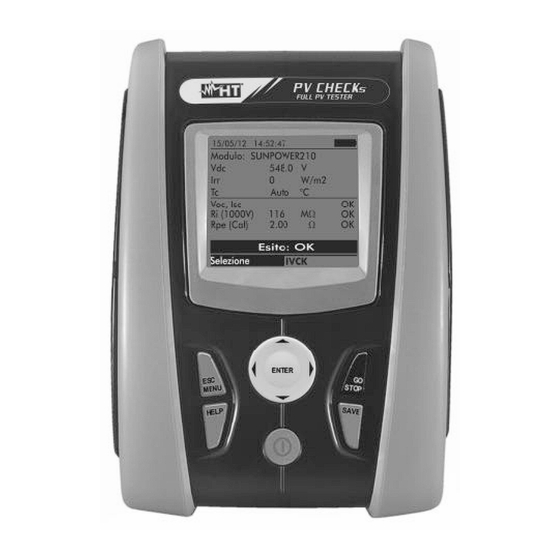
PVCHECKs 4. NOMENCLATURE 4.1. INSTRUMENT DESCRIPTION CAPTION: 1. Inputs 2. Display 3. Connector for optical output/USB port 4. Arrow keys/ENTER key 5. GO/STOP key 6. SAVE key 7. ON/OFF key 8. HELP / 9. ESC/MENU key Fig. 1: Description of the front part of the instrument CAPTION: 1. -
Page 12: Keyboard Description
PVCHECKs 4.2. KEYBOARD DESCRIPTION The keyboard includes the following keys: ON/OFF key to switch on/off the instrument ESC/MENU key to exit the selected menu without confirming and to go back to the main menu keys to move the cursor inside the various screens in order to select programming parameters ENTER key to confirm modifications, selected programming parameters and to select the function to be accessed from the menu. -
Page 13: Initial Screen
PVCHECKs 4.4. INITIAL SCREEN When switching on the instrument, the initial screen appears for a few seconds. It shows: P V C H E C K s • The instrument model (PVCHECKs) • The manufacturer’s name • The presence of the enabled internal module for RF R F S N : 1 5 3 4 5 6 7 8 connection •... -
Page 14: General Menu
PVCHECKs 5. GENERAL MENU EN - 12... -
Page 15: Set - Instrument Settings
PVCHECKs Pressing the ESC/MENU key in any condition of the 15/05/12 15:34:26 instrument displays the general menu screen, in which the instrument may be set, the saved measures can be displayed I V C K Te s t m o d . / s t r i n g s and the desired measuring function may be selected. -
Page 16: Measuring Unit
PVCHECKs 5.1.2. Measuring unit This section allows setting the measuring units of some parameters included in the database (DB) for the management of PV modules (see § 5.6) when measuring IVCK. 1. Position the cursor onto “Measuring Unit” by using the 15/05/12 15:34:26 arrow keys (,) and confirm with ENTER. -
Page 17: Remote Unit/Pyranometer
PVCHECKs 5.1.4. Remote unit/Pyranometer This section allows selecting the type of remote unit to be used (if available) and setting the values of typical parameters (Sensitivity and Alpha) of the reference irradiance cell supplied with the instrument. The values of these parameters, which are printed on the back label of the cell, depend on the type of PV module being tested. -
Page 18: Irradiance
PVCHECKs 5.1.5. Irradiance This section allows setting the minimum irradiance threshold both for IVCK measurement and for efficiency test on a PV installation. 1. Position the cursor onto “Irradiance” by using the arrow 15/05/12 15:34:26 keys (,) and confirm with ENTER. 2. - Page 19 PVCHECKs setting the corrective factor in the following range 0.950 to 1.050. Set the desired values by means of the arrow keys ( , ). 3. Press the SAVE key to save the settings made; the message “Data saved” will be displayed for a few seconds.
-
Page 20: Eff - Efficiency Test Settings For Pv Installations
PVCHECKs 5.2. EFF – EFFICIENCY TEST SETTINGS FOR PV INSTALLATIONS The purpose of this measurement is to evaluate the DC efficiency of a photovoltaic installation, with the possibility of obtaining a positive or negative result of the check/ recording depending on a limit on the nDC parameter, freely set by the user. For this test, the use of the optional remote unit SOLAR-02 is necessary (see §... -
Page 21: System Parameters
PVCHECKs 3600s. ➢ The FS of the DC clamp used for measuring DC current with value selectable between 1A ÷ 3000A 5. Press the SAVE key to save the settings made; the message “Data saved” will be displayed for a few S AV E t o s t o r e seconds. - Page 22 PVCHECKs I n s t r u m e n t s e t t i n g s Selection E F F 4. By using the arrow keys ( , ) it is possible to set: 15/05/12 15:34:26 ➢ Pmax maximum total rated power of PV installation expressed in kW P m a x : : 3 .
-
Page 23: Selection Of The Compensation Relationship Of Temperature Effects
PVCHECKs 5.2.3. Selection of the compensation relationship of temperature effects This option allows selecting the relationship to be used to correct the measurements performed according to the modules’ temperature as regards the calculation of nDC efficiency. The following modes are available: T.Mod.: Correction factor Rfv2 related to PV module Temp. - Page 24 PVCHECKs Absolute value of the thermal coefficient of Pmax of the PV modules included in the %/ ° γ plant section being measured. (Normal Operating Cell Temperature) = Temperature the cells under reference %/ ° NOCT conditions are brought to (800W/m , 20°C, AM=1.5, air speed =1m/s).
-
Page 25: Lowω - Settings For Continuity Test With 200Ma
PVCHECKs 5.3. LOWΩ – SETTINGS FOR CONTINUITY TEST WITH 200MA The purpose of this measurement is to test the continuity of protective conductors and equipotential ones (e.g. from rod to earth and connected foreign earth) and earth rods of SPDs on PV installations. The test must be carried out using a test current > 200mA according to the prescriptions of IEC/EN62446 guideline 5.3.1. - Page 26 PVCHECKs message “Data saved” will be displayed for a few seconds. Press the ESC/MENU key to exit without saving and go back to the previous screen. S AV E t o s t o r e L O W Ω Selection CAUTION The settings saved for max RPE also affect the settings for the Continuity...
-
Page 27: Mω - Settings For Insulation Measurement
PVCHECKs 5.4. MΩ – SETTINGS FOR INSULATION MEASUREMENT 5.4.1. Instrument settings 15/05/12 15:34:26 1. Position the cursor onto MΩ by using the arrow keys (,) and confirm with ENTER. The display shows the following screen: I n s . T e s t 1 0 0 0 Ω... - Page 28 PVCHECKs ➢ Test time maximum value of test time (only for TIMER mode) with a maximum value of 300s in steps Te s t t i m e : 1 0 s of 1s. 5. Press the SAVE key to save the settings made; the message “Data saved”...
-
Page 29: Ivck - Settings For Ivck Quick Test
PVCHECKs 5.5. IVCK – SETTINGS FOR IVCK QUICK TEST The purpose of this measurement is to verify the functionality of the connections and of the strings in a photovoltaic field, according to the provisions of standard IEC/EN62446 by measuring the open circuit voltage and the short-circuit current at operating conditions and referred to STC (via the optional measurement of irradiation) and providing immediate results regarding the measurement just carried out, both in absolute terms and by comparison with the strings previously tested. - Page 30 PVCHECKs 4. Use the arrow keys (,) for option setting, and select 15/05/12 15:34:26 the desired option by means of the arrow keys ( , ). S U N P W R 2 1 0 M o d u l e : The following parameters can be set: M o d .
- Page 31 PVCHECKs EN - 29...
-
Page 32: Db - Database Module Management
PVCHECKs 5.6. DB – DATABASE MODULE MANAGEMENT The meter allows managing up to a maximum of 30 different types of PV modules, further to a DEFAULT module (not editable and not erasable) which can be used as reference case when no piece of information about the type of module being tested is available. - Page 33 PVCHECKs ➢ The “Tech” item is referred to the choose of the technology of the module on test. Select the “STD” option for test on “STANDARD” PV modules, “CAP” option for test on higher capacitive effects PV modules ➢ A wrong choice of the type of technology can lead to a negative outcome of the final test.
-
Page 34: How To Define A New Pv Module
PVCHECKs 5.6.1. How to define a new PV module EN - 32... - Page 35 PVCHECKs 1. Position the cursor onto DB by using the arrow keys 15/05/12 15:34:26 (,) and confirm with ENTER. The display shows the M o d e l : D E F A U L T screen which contains: ...
- Page 36 PVCHECKs 6. Insert the value of each parameter (see Table 1) 15/05/12 15:34:26 according to the possible datasheet of the Manufacturer.). M o d e l : S U N P W R 2 1 0 Position the cursor onto the parameter to be defined by ...
-
Page 37: How To Modify An Existing Pv Module
PVCHECKs 5.6.2. How to modify an existing PV module EN - 35... - Page 38 PVCHECKs 1. Select the PV module to be modified from the internal 15/05/12 15:34:26 database by means of the arrow keys ( , ). M o d e l S U N P W R 2 1 0 2.
-
Page 39: How To Delete An Existing Pv Module
PVCHECKs 5.6.3. How to delete an existing PV module 1. Select the PV module from the internal database by 15/05/12 15:34:26 means of the arrow keys ( , ). M o d e l : S U N P W R 2 1 0 2. -
Page 40: Operating Instructions
PVCHECKs 6. OPERATING INSTRUCTIONS 6.1. MEASURING EFFICIENCY PV PLANTS BY USING REMOTE UNIT SOLAR-02 For the sake of simplicity, further in this section, the word “string” will be used, although often the term “photovoltaic field” would be more correct. From the point of view of the instrument, the management of a single string or of more parallel strings (PV field) is identical. - Page 41 PVCHECKs of the DC clamp, to the integration period and to the parameters of the system being measured (see § 5.1.4, § 5.1.5, § 0, § 5.2.1 and § 5.2.2). 4. In order to guarantee the operator’s safety, disable the system being measured by means of the switches/breakers upstream and downstream of the DC/AC converter (inverter).
- Page 42 PVCHECKs G o t o S t a r t Selection E F F 13. Keeping the remote unit SOLAR-02 always close to the 15/05/12 15:34:26 main unit, press the GO/STOP key on PVCHECKS to start testing. The message “Waiting start recording…” appears on the display of the main unit and “HOLD”...
- Page 43 PVCHECKs 15. At any time it will be possible to analyze the current 15/05/12 15:35:00 recording status by pressing the MENU key. The following information will be shown: S t a r t 1 5 / 0 5 / 1 2 1 5 : 3 0 : 0 0 ➢...
-
Page 44: Measuring Parameters On Pv Plant Without Using Solar-02
PVCHECKs recording, the Irradiance values reached the “stable” condition and its values were higher than the minimum P d c 3 . 1 2 5 irradiance threshold V d c 3 8 9 ➢ Unable to carry out the analysis if irradiance has never I d c 8 . - Page 45 PVCHECKs programmable integration period (see § 5.2.1). In this mode, the values of Irradiation, Te, Tc, the nDC efficiency value are not evaluated and no result is provided by the instrument. CAUTION • The maximum voltage between inputs P and N is 1000VDC. Do not measure voltages exceeding the limits given in this manual.
- Page 46 PVCHECKs BEFORE CONNECTING THE DC CLAMP TO THE CONDUCTORS Switch on the clamp, check the LED indicating the status of the clamp’s internal batteries (if present), select the correct range, press the ZERO key on the DC clamp and check on the display of PVCHECKs the actual zeroing of the corresponding Idc value (values up to 0.02A are acceptable).
- Page 47 PVCHECKs instrument’s display. P n o m 3 . 5 0 0 ° C ° C P d c 3 . 1 2 5 V d c 3 8 9 I d c 8 . 0 1 - - - n d c R e c o r d i n g r u n n i n g …...
-
Page 48: Quick Check On Pv Modules And Strings (Ivck)
PVCHECKs 6.3. QUICK CHECK ON PV MODULES AND STRINGS (IVCK) 6.3.1. Foreword This function carries out a series of quick tests on a PV module/string, measuring in a sequence: ➢ The Voc voltage and the short-circuit current Isc according to the prescriptions of standard IEC/EN62446 with the possibility of measuring (by using the relevant probes) also the irradiance and module temperature values. -
Page 49: Carrying Out An Ivck Quick Test Without Measuring Irradiance
PVCHECKs 6.3.2. Carrying out an IVCK quick test without measuring irradiance EN - 47... - Page 50 PVCHECKs CAUTION • The maximum voltage between inputs P, N, E and C is 1000VDC. Do not measure voltages exceeding the limits given in this manual • Do not perform test on PV modules or strings connected to the DC/AC converter •...
- Page 51 PVCHECKs Fig. 6: Connection for IVCK test without irradiance measurement CAUTION Upon pressing the GO/STOP key, different error messages can be displayed by the instrument (see § 6.6) and, therefore, the test cannot be started. Check and eliminate, if possible, the problem causing the error message before going on with the test.
- Page 52 PVCHECKs 13.With continuity measurement selected, the instrument 15/05/12 15:34:26 goes on by opening the short-circuit and carrying out the M o d u l e S U N P W R 3 1 8 test between terminals E and C. V d c 5 4 8 .
- Page 53 PVCHECKs VocAvg − Esito × ≤ VocAvg IscAvg − Esito × ≤ IscAvg ➢ The overall value of the results: o OK: if all results under OPC are OK, o NO if one of the results under OPC is NO 17.Press the ...
-
Page 54: Carrying Out An Ivck Quick Test And Measuring Irradiance
PVCHECKs 6.3.3. Carrying out an IVCK quick test and measuring irradiance EN - 52... - Page 55 PVCHECKs CAUTION • The maximum voltage between inputs P, N, E and C is 1000VDC. Do not measure voltages exceeding the limits given in this manual. • Do not perform test on PV modules or strings connected to the DC/AC converter •...
- Page 56 PVCHECKs and, therefore, the measurements carried out by the instrument CANNOT be considered reliable. Repeat the same operations at another daytime. 10. Fasten the bracket to the module by using the supplied set of screws and mount the reference cell on it, if possible with output terminals facing downwards. Rotate the cell until it rests on the tang found on the bracket so that the cell is perfectly parallel to the surface of the module, then fix it with the relevant screws provided.
- Page 57 PVCHECKs CAPTION: Green cable Blue cable Red cable Black cable 1. PV module/string 2. Main system earthing 3. Earthed metal structure in the system 4. Reference cell for irradiance measurement 5. Te m p e r a t u r e s e n s o r ( i f required) Fig.
- Page 58 PVCHECKs SOLAR-02 Ω R i ( 1 0 0 0 V ) - - - Ω R p e ( C a l ) - - - I V C K Selezione CAUTION Upon pressing the GO/STOP key, different error messages can be displayed by the instrument (see §...
- Page 59 PVCHECKs positive (measured values within the tolerances set on the instrument) V d c 5 4 8 . 0 V 17.With insulation measurement selected, the instrument I r r 8 5 6 W / m 2 goes on with the test keeping terminals P and N short- A u t o °...
-
Page 60: Reset Averages
PVCHECKs In general: 7 8 7 V o c @ S T C 5 . 7 2 I s c @ S T C Outcome: OK I V C K VocNom − Esito × ≤ VocNom IscNom − Esito ×... - Page 61 PVCHECKs 15/05/12 15:34:26 1. In IVCK mode, press the ENTER key, select “Reset Averages” and confirm by pressing ENTER again to M o d u l e S U N P W R 3 1 8 zero the average values calculated until that moment. V d c 0 .
-
Page 62: Anomalous Situations When Performing Ivck Tests
PVCHECKs 6.3.4.1. Anomalous situations when performing IVCK tests EN - 60... - Page 63 PVCHECKs 15/05/12 15:34:26 1. In case the instrument detects a voltage higher than 1000V at terminals P-N, P-E and N-E, it does not carry M o d u l e S U N P W R 3 1 8 out the test, gives out a long sound and displays the V d c 0 .
- Page 64 PVCHECKs Ω R i ( 1 0 0 0 V ) - - - Ω R p e ( C a l ) - - - Voltage > Limit Selection I V C K 15/05/12 15:34:26 4. In case the instrument detects an Isc current higher than 15A, it does not carry out the test, gives out a long sound M o d u l e S U N P W R 3 1 8...
-
Page 65: Measurement Of Insulation On Pv Modules/Strings/Fields (Mω)
PVCHECKs 6.4. MEASUREMENT OF INSULATION ON PV MODULES/STRINGS/FIELDS (MΩ) 6.4.1. Foreword The purpose of this function is to measure the insulation resistance of the active conductors of a module, string, of a whole PV field and of possible unearthed metal masses according to the prescriptions IEC/EN62446 guideline. -
Page 66: Measuring Insulation - Field Mode
PVCHECKs 6.4.2. Measuring insulation – FIELD mode 1. Position the cursor onto MΩ by using the arrow keys 15/05/12 15:34:26 (,) and confirm with ENTER. The display shows the screen to the side: I n s . T e s t 1 0 0 0 2. - Page 67 PVCHECKs Fig. 10: Instrument connection for insulation measurement in FIELD mode CAUTION Upon pressing the GO/STOP key, different error messages can be displayed by the instrument (see § 6.6) and, therefore, the test cannot be started. Check and eliminate, if possible, the problem causing the error message before going on with the test.
-
Page 68: Measuring Insulation - Timer Mode
PVCHECKs 6.4.3. Measuring insulation – TIMER mode 1. Position the cursor onto MΩ by using the arrow keys 15/05/12 15:34:26 (,) and confirm with ENTER. The display shows the screen to the side. I n s . T e s t 1 0 0 0 2. - Page 69 PVCHECKs Upon pressing the GO/STOP key, different error messages can be displayed by the instrument (see § 6.6) and, therefore, the test cannot be started. Check and eliminate, if possible, the problem causing the error message before going on with the test. 4.
-
Page 70: Measuring Insulation - String Mode
PVCHECKs Te s t t i m e : 2 0 0 s Outcome: OK M Ω 6.4.4. Measuring insulation – STRING mode CAUTION • The maximum current which can be measured by the instrument is 15A. Before carrying out the measures of Insulation in "STRING" mode, always ensure that the instrument is connected to ONE STRING and not more strings in parallel to avoid possible damage of •... - Page 71 PVCHECKs ➢ key access to the second page with the M Ω measured values of VPN, VEP and VEN voltages Selection 3. Connect the instrument to the PV module/string being tested and to the main earth node of the system as shown in . In particular, connect the negative output pole of the PV field to terminal N and the positive output pole of the PV field to terminal P.
- Page 72 PVCHECKs Measuring… M Ω Selection 5. When measurement is complete, the instrument provides 15/05/12 15:34:26 the Ri value, i.e. the minimum value of insulation resistance of the of other objects being tested, continuously measured during the whole duration of I n s . T e s t 1 0 0 0 measurement.
-
Page 73: Anomalous Situations
PVCHECKs 6.4.4.1. Anomalous situations 1. In any operating mode, in case the instrument detects a 15/05/12 15:34:26 voltage higher than 1000V at terminals P-N, P-E and N- E, it does not carry out the test, gives out a long sound I n s . - Page 74 PVCHECKs Current < Lim M Ω Selection 15/05/12 15:34:26 4. In STRING mode, in case the instrument detects a voltage < 15V between terminals P and N, it does not carry out the test and displays the message “Low I n s . T e s t 1 0 0 0 voltage”.
-
Page 75: Measurement Of Continuity On Pv Modules/Strings/Fields (Lowω)
PVCHECKs 6.5. MEASUREMENT OF CONTINUITY ON PV MODULES/STRINGS/FIELDS (LOWΩ) 6.5.1. Foreword The purpose of this measurement is to test the continuity of protective conductors and equipotential ones (e.g. from rod to earth and connected foreign earth) and earth rods of SPDs on PV installations. - Page 76 PVCHECKs Leads calibration S e t t i n g s L O W Ω Selection 15/05/12 15:34:26 4. Press GO/STOP to start calibration. The message “Measuring…” is shown on the display. 5. At the end of the compensation procedure, in case the Ω...
-
Page 77: Measuring Continuity
PVCHECKs 6.5.3. Measuring continuity 1. Position the cursor onto LOWΩ by using the arrow keys 15/05/12 15:34:26 (,) and confirm with ENTER. The display shows the screen to the side. Ω R P E m a x 1 . 0 2. - Page 78 PVCHECKs Upon pressing the GO/STOP key, different error messages can be displayed by the instrument (see § 6.6) and, therefore, the test cannot be started. Check and eliminate, if possible, the problem causing the error message before going on with the test. 15/05/12 15:34:26 5.
-
Page 79: Anomalous Situations
PVCHECKs L O W Ω Selection 6.5.3.1. Anomalous situations 15/05/12 15:34:26 1. In case the instrument detects a voltage higher than 5V at its terminals E and C, it does not carry out the test, gives out a long sound and displays the message “Voltage > Ω... - Page 80 PVCHECKs C a l i b r a t i o n n o t O K L O W Ω Selection 15/05/12 15:34:26 3. In case the instrument detects a resistance higher than 5Ω at its terminals, it gives out a long sound, zeroes the compensated value and displays the message Ω...
-
Page 81: List Of Display Messages
PVCHECKs 6.6. LIST OF DISPLAY MESSAGES MESSAGE DESCRIPTION Function not available The selected function/characteristic is not available Data not saved The instrument was not able to save the data Wrong date Set a correct system date RADIO transmission error The instrument does not communicate via RF with external units SOLAR-02: Firmware incorrect Inconsistent SOLAR-02 FW. - Page 82 PVCHECKs Isc current too high Measured Isc current > 15A Current < Lim Current between P and N lower than the minimum detectable value EEPROM error: contact service Internal instrument error FRAM error: contact service Internal instrument error RTC Error: contact service Internal instrument error RADIO error: contact service Internal instrument error...
-
Page 83: Storing Data
PVCHECKs 7. STORING DATA The instrument allows saving max 999 measured values. The saved data can be recalled at display and deleted at any moment, and can be associated to reference numerical markers relevant to the installation name, the PV string and the PV module (max 250 markers). -
Page 84: Saving Efficiency Measures
PVCHECKs 7.1. SAVING EFFICIENCY MEASURES 1. Press the SAVE key with a measured result shown on the 15/05/12 15:34:26 display. The instrument shows the screen to the side, containing a virtual keyboard. 7 1 2 I r r W / m 2 2. - Page 85 In this case, the new values may be factory selected as an alternative to the buil-in ones, as shown in 0 0 2 instruments the screen to the side. 0 0 1 HT ITALIA EN - 83...
- Page 86 PVCHECKs PV installation 0 0 1 Inverter Area Building Field Plant M o d i f i c a t i o n S AV E CAUTION • Marker strings can be uploaded into the instrument by mean of the TopView software through a PC connection (“Marker manager”).
-
Page 87: Operations With Results
PVCHECKs 7.3. OPERATIONS WITH RESULTS 7.3.1. Recalling on the display the PV efficiency results EN - 85... -
Page 88: Recalling On The Display The Results Of Ivck, Mω And Lowω Measurements
PVCHECKs 1. Press the ESC/MENU key to go back to the main menu, 15/05/12 15:34:26 select “MEM” and confirm with ENTER to access the TYPE section where saved values are displayed. The screen to SMP 08/04/2012 the side is shown by the instrument and contains the saved tests. - Page 89 PVCHECKs 1. Press the ESC/MENU key to go back to the main menu, 15/05/12 15:34:26 select “MEM” and confirm with ENTER to access the DATE TYPE section where saved values are displayed. The screen to 08/04/2012 10:38 LOWΩ the side is shown by the instrument and contains the saved tests.
-
Page 90: Accessing The Data Saved In The Memory - Numeric Display
PVCHECKs 7.3.2.1. Accessing the data saved in the memory – Numeric display EN - 88... - Page 91 PVCHECKs 1. Select a line corresponding to a saved result and press 15/05/12 15:34:26 ENTER. Comments 2. Select “Open” and press ENTER to open the section PV PLANT 1 where measurement results are displayed as: ➢ Numeric screens of measured parameters under 002* PV PLANT 2 standard (STC) conditions and under operating...
- Page 92 PVCHECKs R i ( - ) > 1 0 0 Ω Ω Outcome: OK M Ω Selection 5. For MΩ test in TIMER mode there are the values of 15/05/12 15:34:26 the following parameters: ➢ Set rated test voltage ➢...
-
Page 93: Deleting Data From The Memory
PVCHECKs compared with the Ri min limit by the instrument > 2 0 0 M Ω Outcome: OK M Ω Selection 15/05/12 15:34:26 7. For LOWΩ test, there are the values of the following parameters: ➢ Limit threshold set for continuity measurement Ω... -
Page 94: Connecting The Instrument To The Pc
PVCHECKs 8. CONNECTING THE INSTRUMENT TO THE PC EN - 92... - Page 95 PVCHECKs CAUTION • The connection between instrument and PC is realized by means of cable C2006. • In order to transfer the data onto a PC it is necessary to install beforehand both the management software Topview and the drivers of cable C2006 on the PC itself.
- Page 96 PVCHECKs Connecting to PC M E N U 6. Use TopView controls to activate data transfer (please refer to the on-line help of the programme). EN - 94...
-
Page 97: Maintenance
PVCHECKs 9. MAINTENANCE 9.1. GENERAL INFORMATION The instrument you purchased is a precision instrument. While using and storing the instrument, carefully observe the recommendations listed in this manual in order to prevent possible damage or danger during use. Do not use the instrument in environments with high humidity levels or high temperatures. Do not expose to direct sunlight. -
Page 98: Technical Specifications
PVCHECKs 10.TECHNICAL SPECIFICATIONS 10.1. TECHNICAL SPECIFICATIONS FOR PV INSTALLATION EFFICIENCY [%reading + (no. of digits) * resolution] at 23°C ± 5°C, <80%HR Accuracy is indicated as DC voltage Range [V] Resolution [V] Accuracy 5.0 ÷ 199.9 ±(1.0%rdg + 2dgt) 200.0 ÷ 999.9 DC current (by means of external clamp transducer) Range [mV] Resolution [mV]... -
Page 99: Technical Specifications Of The Ivck Function
PVCHECKs 10.2. TECHNICAL SPECIFICATIONS OF THE IVCK FUNCTION DC Voltage @ OPC Range [V] Resolution [V] Accuracy 5.0 ÷ 199.9 ±(1.0%rdg + 2dgt) 200 ÷ 999 Minimum VPN voltage to start the test: 15V DC Current @ OPC Range [A] Resolution [A] Accuracy 0.10 ÷... -
Page 100: Reference Standards
PVCHECKs Rated current measured > 1mA with 1kΩ @ Vnom Insulation resistance (MΩ) – Mode FIELD (*), STRING (**) Range [MΩ] Resolution [MΩ] Test voltage [V] Accuracy (***) 0.1 ÷ 1.9 250, 500, 1000 ±(20.0%rdg + 5dgt) 2 ÷ 99 (*) For FIELD mode if VPN >1V the minimum voltage VEP and VEN for the calculation of Ri(+) and Ri(-) is 1V (**) For STRING mode... -
Page 101: Environmental Conditions For Use
PVCHECKs 10.6. ENVIRONMENTAL CONDITIONS FOR USE Reference temperature: 23°C ± 5°C (73° ± 41°F) Operating temperature: 0°C ÷ 40°C (32 ÷ 104°F) Allowable relative humidity: <80%RH Storage temperature: -10°C ÷ 60°C (14 ÷ 140°F) Storage humidity: <80%RH Max operating altitude: 2000m This instrument satisfies the requirements of Low Voltage Directive 2014/35/EU (LVD) and of EMC Directive 2014/30/EU... -
Page 102: Appendix - Theoretical Outline
PVCHECKs 11.APPENDIX – THEORETICAL OUTLINE 11.1. EFFICIENCY TEST ON PV INSTALLATIONS According to the requirements of the laws in force, DC efficiency test on a PV installation depends on the type of correction used to compensate the effects of the module’s temperature and on the mathematical relationship used to calculate the nDC parameter (see §... - Page 103 PVCHECKs ➢ Non-displayable: if the obtained values are inconsistent (e.g. nDC >1.15) or if irradiation has never reached a steady value > minimum threshold set. ➢ The maximum performance of the system EN - 101...
-
Page 104: Service
PVCHECKs 12.SERVICE 12.1. WARRANTY CONDITIONS This instrument is warranted against any material or manufacturing defect, in compliance with the general sales conditions. During the warranty period, defective parts may be replaced. However, the manufacturer reserves the right to repair or replace the product. Should the instrument be returned to the After-sales Service or to a Dealer, transport will be at the Customer’s charge. - Page 105 PVCHECKs EN - 1...
- Page 106 PVCHECKs EN - 2...
- Page 107 Tel: +39 0546 621002 Fax: +39 0546 621144 eMail: ht@htitalia.it Web: www.ht-instruments.com HT INSTRUMENTS BRASIL Rua Aguaçu, 171, bl. Ipê, sala 108 13098321 Campinas SP - BRA Tel: +55 19 3367.8775 Fax: +55 19 9979.11325 eMail: vendas@ht-instruments.com.br Web: www.ht-instruments.com.br HT INSTRUMENTS USA LLC...
Need help?
Do you have a question about the PV CHECKs and is the answer not in the manual?
Questions and answers