SystemAir SAVE VTC 200-1 Installation Instructions Manual
Hide thumbs
Also See for SAVE VTC 200-1:
- Service & accessories installation manual (50 pages) ,
- User manual (18 pages)

Related Manuals for SystemAir SAVE VTC 200-1


Summary of Contents for SystemAir SAVE VTC 200-1
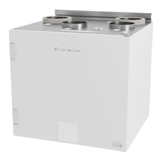
- Page 1 SAVE VTC 200 – 1 Installation instructions Document in original language | 398085 · v01...
- Page 2 This also applies to products already ordered, as long as it does not affect the previously agreed specifications. Systemair is not liable or bound by warranty if these instructions are not adhered to during installation or service. 398085 | v01...
-
Page 3: Table Of Contents
Contents Overview ............1 12 EU Declaration of Conformity ......14 General Description ........1 Warranty ..........1 Type label..........1 Important Safety Information ......1 Intended Use.........1 Admonitions .........2 Technical Data ..........2 Dimensions and Weight ......3 Connections Left and Right models.....5 Installation recommendation regarding condensation ........5 3.3.1 Condensation inside of the... -
Page 5: Overview
For the assertion of warranty claims, the products must be correctly connected and operated, and used in accordance with the data sheets. Further prerequisites are a completed maintenance plan with no gaps and a commissioning re- port. Systemair will require these in the case of a warranty claim. Type label Before calling your service representative, make a note of the specification and production number from the type label, which can be found next to the external connections and inside of the unit. -
Page 6: Admonitions
| Technical Data • The system should operate continuously, and only be stopped for maintenance/service. • Do not connect tumble dryers to the ventilation system. • Make sure that filters are mounted before starting the unit. Admonitions Danger • Make sure that the mains supply to the unit is disconnected before performing any maintenance or electrical work! •... -
Page 7: Dimensions And Weight
Technical Data | Dimensions and Weight Fig. 2 Dimensions of left hand unit 398085 | v01... - Page 8 | Technical Data Fig. 3 Dimensions of right hand unit *** Drainage. The unit weight is 47 kg. 398085 | v01...
-
Page 9: Connections Left And Right Models
Technical Data | Connections Left and Right models Fig. 4 Duct connections Position Description Right hand model (Supply air connection is situated on the right hand side of the unit viewed from the front) Left hand model (Supply air connection panel is situated on the left hand side of the unit viewed from the front) Symbol Description... -
Page 10: Condensation Outside Of The Unit
• Check completeness of the delivery. Verify that all ordered equipment is delivered before starting the installation. Any discrepancies from the ordered equipment must be reported to the supplier of Systemair products. Warning When opening the transport packaging, there is a risk of damage from sharp edges, nails, staples, splinters etc. -
Page 11: Location And Space Requirements
Installation | Location and Space Requirements The SAVE VTC 200 – 1 should preferably be installed in a separate room (e.g. storeroom, laundry room or similar.). When choosing the location it should be kept in mind that the unit requires maintenance regularly and that the in- spection door should be easily accessible. -
Page 12: Condensation Drainage
| Installation Ø8, 50mm x8 C — concrete/bricks, W — wood block, G — gypsum, M — mineral wool X* — adaptable height according to needs. Make sure the mounting bracket is completely level. Follow the ventilation drawing when connecting the unit to the duct system. Condensation drainage Depending on the relative humidity in the extract air, condensation may occur on the cold surfaces of the unit. -
Page 13: Ventilation Duct Connection And Insulation
Electrical connections | The drainage on the supply air side are mounted with an end cap at delivery. In summer periods, when the outdoor air has a high humidity and the indoor air is cool, condensation can occur on the supply air side. Remove the end cap and connect a hose (available as an accessory). -
Page 14: External Connections (Connection Board)
| Electrical connections Fig. 6 Main circuit board connections Position Description Connection to the external connection box Terminals for a heater Terminals for a TRIAC Terminals for the mains power supply Terminals for power supply of extract air fan Terminals for power supply of supply air fan Terminals for internal relative humidity/temperature sensor Analog input 1 —... -
Page 15: Before Starting The System
Before Starting the System | Fig. 7 External connection box and board Position Description Connection to the main circuit board Connection for external control panel (HMI) or Internet access module (IAM) Modbus RS485 connection AI6–7 Freely configurable Analog input. None/Input type selection in HMI. DO1–4 Freely configurable digital output. -
Page 16: Concluding Routines
| Concluding Routines Note: If the SAVE LIGHT control panel is used, the start-up wizard is skipped and the factory settings are used. Select language, set the time and choose airflow control type. Select revolutions per minute as the type of airflow con- trol only if these values are included with the device. -
Page 17: Disposal And Recycling
Disposal and recycling | Disposal and recycling This product is compliant with the European WEEE Directive and related national waste legislation. When disposing the unit, follow your local rules and regulations. This product packing materials are recyclable and can be reused. Do not dispose in household waste. - Page 18 | EU Declaration of Conformity EU Declaration of Conformity Manufacturer EN 50106 Systemair UAB Safety of household and similar appliances – Particular Linų st. 101 rules for routine tests referring to appliances under the LT–20174 Ukmergė, LITHUANIA scope of EN 60 335-1.
- Page 19 398085 | v01...
- Page 20 Systemair UAB Linų st. 101 LT–20174 Ukmergė, LITHUANIA Phone +370 340 60165 Fax +370 340 60166 www.systemair.com...
Need help?
Do you have a question about the SAVE VTC 200-1 and is the answer not in the manual?
Questions and answers