SystemAir SAVE VTR 150/K User Manual
Hide thumbs
Also See for SAVE VTR 150/K:
- User manual (98 pages) ,
- Service & accessories installation manual (52 pages) ,
- Installation and service (50 pages)
Table of Contents
Advertisement
Quick Links
Advertisement
Table of Contents

Related Manuals for SystemAir SAVE VTR 150/K


Summary of Contents for SystemAir SAVE VTR 150/K
- Page 1 SAVE VTR 150/K User Manual Document in original language | 254493 · v01...
- Page 2 © Copyright Systemair UAB All rights reserved E&OE Systemair UAB reserves the rights to change their products without notice. This also applies to products already ordered, as long as it does not affect the previously agreed specifications. 254493 | v01...
-
Page 3: Table Of Contents
Contents Overview ............1 5.8.2 Checking the outdoor air intake ........15 General Description ........1 5.8.3 Checking the roof cowl (if Warranty ..........1 fitted)........15 Type label..........1 5.8.4 Checking and cleaning the Warnings............1 duct system ......15 Cooker hood ..........2 Troubleshooting..........15 Operation ............2 Electrical data .......... -
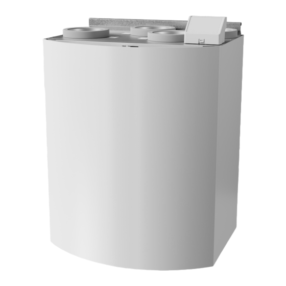
Page 5: Overview
For the assertion of warranty claims, the products must be correctly connected and operated, and used in accordance with the data sheets. Further prerequisites are a completed maintenance plan with no gaps and a commissioning re- port. Systemair will require these in the case of a warranty claim. Type label Before calling your service representative, make a note of the specification and production number from the type label, which can be found next to the external connections and inside of the unit. -
Page 6: Cooker Hood
| Cooker hood Warning • This product is not intended to be used by children or people with reduced physical or mental ability or lack of experience and knowledge, if no instruction concerning the use has been given by the person responsible for their safety or that this person is supervising the operation. -
Page 7: Indicators
Operation | 4.1.1 Indicators General alarm LED shows when any alarm has occurred. Alarm type is not specified. It is not possible to acknowledge alarms from the SAVE LIGHT control panel. Please check SAVE TOUCH control panel or contact your local technical service provider. The filter change LED shows when filters have to be replaced. -
Page 8: Save Touch Control Panel / Save Connect
| Operation 2. Press button to increase and button decrease the value. Address value can be changed from 6 to 10, default value is 10. Address value Indication Low airflow LED is on Normal airflow LEDs are on High airflow LEDs are on Refresh mode LEDs are on All LEDs are on SAVE TOUCH control panel / SAVE CONNECT... -
Page 9: Home Screen Overview
Operation | 4.2.2 Home screen overview 1. Menu 2. Active user mode 3. Temperature settings 4. Airflow settings 5. Alarms and warnings 6. Status line 7. Outdoor temperature A. Return to home screen E. Check and change remaining time till filter change B. -
Page 10: Quick Information Screen
The top circle on the home screen indicates a currently active user mode. Touch the symbol to change the mode. Duration have to be set for temporary user modes. SAVE VTR 150/K will return to its previous working mode after the set time expires. -
Page 11: To Change The Temperature
Operation | Icon Text Description Automatic airflow control. AUTO mode is available for selection when Demand Control, Week Schedule and/or external fan control functions are configured, otherwise AUTO mode icon won’t be visible in active user modes menu. AUTO Auto mode activates Demand Control, Week Schedule and/or external fan control functions. -
Page 12: To Change The Airflow
| Operation Use up and down arrows to increase or decrease a value. The default setting is 18 °C. ECO mode is a power saving function which partially limits heater operation and can only be activated if a heater is installed. 4.2.7 To change the airflow Touch the fan symbol on the home screen. -
Page 13: Maintenance
Maintenance | Touch the slider to the right to activate scheduled period. Set the time. Touch the START TIME or END TIME values to change time. Use arrow buttons to increase or decrease value. Confirm with OK button. Note: Scheduled time can start but never end at midnight (00:00). The latest END TIME period is 23:59. Scheduled time cannot go to the next day. -
Page 14: To Clean The Cooker Hood
1. It is recommended to do this every 5 years and is normally carried out by authorized companies specialized in this area. • Use original spare parts from Systemair only. • Scan the code on the type label to find a spare part list. -
Page 15: To Change Filters
Maintenance | The inner front is mounted with four screws. Loosen the screws and pull the inner front towards you. Mount the inner front and tighten the mounting screws properly to prevent air leakage. Note: When mounting the inner front, note the two guide screws at the bottom of the inner front. -
Page 16: To Reset The Filter Change Time
| Maintenance 5.4.1 To reset the filter change time Once filter is changed, it is necessary to reset filter time. Go to Filter menu (see 4.2.2 Home screen overview, page 5, pos. E) or if filter alarm is present, click on alarm status line (see 4.2.2 Home screen overview, page 5, pos. 5) and select filter alarm. -
Page 17: To Clean Fans
Maintenance | Even if the required maintenance is carried out, dust will build up in the ex- changer block. It is therefore of vital importance for the upkeep of a high effi- ciency that the exchanger block is removed from the unit and cleaned periodically as described below. - Page 18 | Maintenance In case both welded belts break it is possible to use joint nipple as a temporarily quick repair solution until the welded belt can be replaced with a new one. Depending of how the unit is installed, it may be not necessary to remove the heat exchanger package in order to temporary repair a broken drive belt if the belt pulley can be accessed.
-
Page 19: Duct System Maintenance
Troubleshooting | Duct System Maintenance 5.8.1 Cleaning extract louvres and supply air diffusers The system supplies fresh air to your home and extracts the used indoor air via the duct system and diffusers/louvres. Diffusers and louvres are mounted in ceilings/walls in bedrooms, living room, wet rooms, WC etc. Remove diffusers and louvres and wash in hot soapy water as required (diffusers/louvres must not be exchanged). -
Page 20: Electrical Data
3. Check that the anti vibration lists are fitted to the mounting bracket and to the back of the unit. 4. Check that the rotor belt is not slipping if the unit has rotating heat exchanger. Electrical data SAVE VTR 150/K come with 500 W or 1000 W installed re-heater battery. 500 W 1000 W... - Page 21 254493 | v01...
- Page 22 Systemair UAB Linų st. 101 LT–20174 Ukmergė, LITHUANIA Phone +370 340 60165 Fax +370 340 60166 www.systemair.com...
Need help?
Do you have a question about the SAVE VTR 150/K and is the answer not in the manual?
Questions and answers