
Related Manuals for SystemAir SAVE VSC 100


Summary of Contents for SystemAir SAVE VSC 100
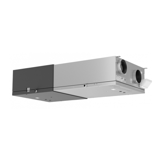
- Page 1 SAVE VSC 100 Installation instructions Document in original language | 333585 · v1.1...
- Page 2 This also applies to products already ordered, as long as it does not affect the previously agreed specifications. Systemair is not liable or bound by warranty if these instructions are not adhered to during installation or service. 333585 | v1.1...
-
Page 3: Table Of Contents
Contents Overview ............1 General Description ........1 Warranty ..........1 Type label..........1 Important Safety Information ......1 Intended Use.........1 Admonitions .........2 Technical Data ..........2 Dimensions and Weight ......2 Duct connections........3 Installation recommendation regarding condensation ........3 3.3.1 Condensation inside of the unit .........3 3.3.2 Condensation outside of the unit .........3 Delivery, Transport, Storage.......4... -
Page 5: Overview
For the assertion of warranty claims, the products must be correctly connected and operated, and used in accordance with the data sheets. Further prerequisites are a completed maintenance plan with no gaps and a commissioning re- port. Systemair will require these in the case of a warranty claim. Type label Before calling your service representative, make a note of the specification and production number from the type label, which can be found next to the external connections and inside of the unit. -
Page 6: Admonitions
| Technical Data • The system should operate continuously, and only be stopped for maintenance/service. • Do not connect tumble dryers to the ventilation system. • Make sure that filters are mounted before starting the unit. Admonitions Danger • Make sure that the mains supply to the unit is disconnected before performing any maintenance or electrical work! •... -
Page 7: Duct Connections
Technical Data | Duct connections Description Description Symbol Symbol Supply air Outdoor air Exhaust air Extract air Installation recommendation regarding condensation 3.3.1 Condensation inside of the unit The unit should run continuously. If the unit is intended to be stopped by the user manually or due to calendar function we recommend to install air tight dampers at extract and supply air ducts. -
Page 8: Delivery, Transport, Storage
Transport and storage The SAVE VSC 100 should be stored and transported in such a way that it is protected against physical damage. It should be covered so dust, rain and snow cannot enter and damage the unit and its components. -
Page 9: Prerequisites For Installation
Access to Power supply The SAVE VSC 100 is supplied with approximately 1 – 1,5 m cable and plug for 230V, single phase earthed connection. Make sure a power outlet is reachable by the plug. - Page 10 | Installation Make sure that the surface is flat and that it supports the weight of the unit. Perform the installation in accordance with local rules and regulations. 333585 | v1.1...
-
Page 11: Ventilation Duct Connection And Insulation
Connect the condensate drainage to the 2 drain plugs in the bottom of the unit. Make sure to use correct drain traps on both connections. The height (H) must be at least 60 mm. Drain traps are not included on delivery and can not be ob- tained from Systemair. Ventilation Duct Connection and Insulation Important •... -
Page 12: Electrical Connections
| Electrical connections Electrical connections Main circuit board layout The SAVE VSC 100 is equipped with built-in regulation and internal wiring. Fig. 3 Main circuit board connections Position Description Connection to the external connection box Terminals for a heater Terminals for a TRIAC... -
Page 13: External Connections (Connection Board)
Before Starting the System | Position Description Terminals for speed control of extract air fan Terminals for speed control of supply air fan External connections (Connection board) External connections to the main circuit board are done via connection board situated inside of the unit. Fig. -
Page 14: Commissioning
| Commissioning • The unit is correctly wired Commissioning Follow the first startup instructions and fill in the Commissioning record as you go through the settings. The Startup Wizard cannot be skipped. Note: If the SAVE LIGHT control panel is used, the start-up wizard is skipped and the factory settings are used. Select language, set the time and choose airflow control type. -
Page 15: Disposal And Recycling
Disposal and recycling | 3. Make sure that the Commissioning record is complete. 4. Collect all tools. 5. Inform the appropriate person that work is finished. 6. Follow the procedures for the return and disposal of replacement parts and the disposal of packing. Disposal and recycling This product is compliant with the European WEEE Directive and related national waste legislation. -
Page 16: Eu Declaration Of Conformity
Degrees of protection provided by enclosures (IP Code). The manufacturer hereby confirms that EN 62233 SAVE VSC 100 Measurement methods for electromagnetic fields of household appliances and similar apparatus with regard comply with all applicable requirements in the following to human exposure. - Page 17 333585 | v1.1...
- Page 18 Systemair UAB Linų st. 101 LT–20174 Ukmergė, LITHUANIA Phone +370 340 60165 Fax +370 340 60166 www.systemair.com...
Need help?
Do you have a question about the SAVE VSC 100 and is the answer not in the manual?
Questions and answers