SystemAir SAVE VTR 500 Installation And Service
Hide thumbs
Also See for SAVE VTR 500:
- User manual (96 pages) ,
- Installation instructions manual (18 pages) ,
- How-to (8 pages)

Related Manuals for SystemAir SAVE VTR 500


Summary of Contents for SystemAir SAVE VTR 500
- Page 1 SAVE VTR 500 Installation and Service Document in original language | 211477 · A001...
- Page 2 This also applies to products already ordered, as long as it does not affect the previously agreed specifications. Systemair is not liable or bound by the warranty if these instructions are not adhered to during installation or service. 211477 | A001...
-
Page 3: Table Of Contents
Contents Declaration of Conformity .........1 Description of User function icons .... 13 Main menu ......... 14 Disposal and recycling ........2 7.7.1 Unit Information ....14 Warnings............2 7.7.2 Alarms ......... 15 About this document........2 7.7.3 Week Schedule...... 18 Product information .........2 7.7.4 Filter ......... -
Page 5: Declaration Of Conformity
Heat recovery ventilation unit: SAVE VTR 500 (The declaration applies only to product in the condition it was delivered in and installed in the facility in accordance with the included installation instructions. The insurance does not cover components that are added or actions carried out subsequently on the product). -
Page 6: Disposal And Recycling
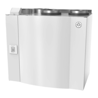
Product information General The SAVE VTR 500 is a heat recovery ventilation unit, with a built in rotating heat exchanger. The SAVE VTR 500 is suit- able for houses with up to 400 m heated living area. -
Page 7: Left And Right Models
Product information | Left and Right models There are two model options, right (R) and left (L) model. The different models are recognized by the placing of the in- ternal components and the supply air outlet, which is situated on left side of the unit on an (L) unit and on the right hand side on an (R) unit. -
Page 8: Transport And Storage
Transport and storage The SAVE VTR 500 should be stored and transported in such a way that it is protected against physical damage that can harm panels etc. It should be covered so dust, rain and snow cannot enter and damage the unit and its components. -
Page 9: Dimensions And Weight, R Model
Product information | 5.5.2 Dimensions and Weight, R model Fig. 2 Dimensions and weight, R model * Water coil connections. ** Drainage. *** Height with mounting bracket. The unit weight is 81 kg. 5.5.3 Duct connections Fig. 3 Duct connections 211477 | A001... -
Page 10: Power Consumption And Fuse Size
The SAVE VTR 500 is supplied with approximately 2 m cable and plug for 230V, single phase earthed connection placed at the bottom of the unit. -
Page 11: How To Remove And Remount The Heat Exchanger
Installation | 1. Prepare the surface where the unit is to be mounted. Make sure that the surface is flat, vertical and that it supports the weight of the unit. Perform the installation in accordance with local rules and regulations. 2. -
Page 12: Savecair Control
| SAVECair control SAVECair control General SAVECair is a modern touchscreen LCD control panel, simply known as HMI — Human Machine Interface. The touchscreen display provides information about current state of the unit and allows you to control all system functions. Settings are done by touching the icons or options. -
Page 13: Menu Overview
SAVECair control | Menu overview A. Return to home screen B. Basic read-only information about the unit C. Currently active alarms and alarm history D. Configure and check week schedule E. Check and change remaining time till filter change F. General system preferences G. -
Page 14: Home Screen
| SAVECair control Home screen Touching home icon (pos. A) in drop- down menu list (pos. 1) will always returns you to home screen after commissioning. 1. Drop-down menu list 2. Active user mode 3. Airflow settings 4. Temperature settings 5. - Page 15 SAVECair control | Icon Text Description Sets speed of both supply and extract air fans to Low levels when user is away from home for a long period of time. HOLIDAY ECO mode is active. Delay in days. Sets speed of both supply and extract air fans to maximum High levels and temperature setpoint offset to –3 K when apartment is more crowded than usual.
-
Page 16: Temperature Settings
| SAVECair control 7.5.2 Temperature settings Temperature can be set at SET TEMPERATURE menu accessible from the home screen by touching TEMPERATURE icon with thermometer. Default temperature value is 18°C (range 12–30°C). Use up and down arrows or a slider to change the value. Then touch the SET to confirm changes. -
Page 17: Indoor Air Quality
SAVECair control | Important It is not recommended to set fan to Off in standard households. If manual fan stop is activated, the unit should be provided with dampers in exhaust and fresh air ducts to avoid cold draught and risk of condensation when the unit has been stopped. -
Page 18: Main Menu
| SAVECair control Icon Text Description Function prevents formation of the ice on the heat exchanger during cold Defrosting outdoor temperatures. Warm air from the living space is used to defrost the heat exchanger using a damper inside the outdoor air duct. The unit switches from outdoor air to Secondary air secondary air while the extract air fan stops and warm secondary air increases the temperature inside the heat exchanger. -
Page 19: Alarms
SAVECair control | 7.7.1.1 Components Type and settings of heat exchanger, heater, cooler, extra controller. 7.7.1.2 Sensors Values from sensors and load of fans (rpm). 7.7.1.3 Input Status Status of configured analog, digital and universal inputs. Connected component type and raw value (volts) is displayed. 7.7.1.4 Output Status Status of configured analog, digital and universal outputs. - Page 20 | SAVECair control Alarm name Explanation Do the following Indicates failure of pre-heater to Check the pre-heater reset button. Defrosting error preheat the incoming outdoor air (in Check the pre-heater cabling. case Extra controller is configured as Contact your installation company or place of purchase.
- Page 21 SAVECair control | Alarm name Explanation Do the following Rotor guard Indicates a rotor malfunction. If the rotating heat exchanger has No rotation guard signal for 180 stopped. Check the rotor belt. seconds. If the heat exchanger is still rotating, check that the quick connector for the sensor is connected and that there is an air gap of 5-10 mm...
-
Page 22: Week Schedule
| SAVECair control Alarm name Explanation Do the following Time for filter change. Change the filter. Filter Change filter according to the instructions in the User Manual. Details about filter retailers can be found in Help menu. Extra controller alarm Error from external device. -
Page 23: Filter
SAVECair control | 7.7.3.1 Schedule airflow settings Touch settings icon to go to SCHEDULE AIRFLOW SETTINGS menu. In this menu set airflow level for scheduled and unscheduled periods. Available levels: Off, Low, Normal, High or Demand. Set temperature setpoint offset for both periods (-10°C – 0°C). Demand level is available only if Demand Control or External fan function is active. -
Page 24: System Preferences
| SAVECair control 7.7.5 System Preferences Configuration of unit location, language and time. Change the following information: • Language (default language is English) • Country (default country is UK) • Unit address (address, post code) • Unit date and time, activate or deactivate summer/winter time switch. Time will automatically change between summertime and wintertime according to European standard, based on Greenwich time zone and set unit location. - Page 25 SAVECair control | 7.7.6.2 Output Configuration of outputs. Settings for analog, digital and universal output terminals on the main board and connection board, configuration of functionality. Fan output PWM (Pulse-width modulation) signal and triac output are already pre-addressed to specific terminals and cannot be changed, all other outputs are free for configuration by commissioning.
- Page 26 | SAVECair control • Set outdoor air temperature interlock. Default setting is 10°C. Range: 0–20°C. • Set actuator type. Default value is 0–10 V Range: 0–10 V / 2–10 V / 10–0 V / 10–2 V. • Set circulation pump stop delay. Default setting is 5 minutes. This option is available if Water / Change-over heat- er type is selected.
- Page 27 SAVECair control | Pressure Setting Flow (CAV) Manual External (VAV) Pa, inwc Airflow l/s, m /h, cfm measurement unit. P-Band 0–100% 0–3000 rpm 0–500 Pa 0–100% Default setting: 150 Pa I-time Off / 1–240 sec. Off / 1–240 sec. Off / 1–240 sec. Off / 1–240 sec.
- Page 28 | SAVECair control Set I-time, default setting is Off, Range: Off/1–120 sec. • Select airflow level for Improving Air Quality. Range: Normal / High / Max. • Select airflow level for Good Air Quality. Range: Low / Normal. RH Transfer Control Note: Setting is available if heat exchanger type is set as Rotating.
- Page 29 Fan speed differ for each household because of different unit size, duct system and system pressure. In order to find correct fan speed, external tool must be used at Systemair website. 1. Go to Systemair website and find your unit.
-
Page 30: Help
| SAVECair control • Shows communication information for HMI. Modbus device number (1–10) and Modbus termination: Active/ Inactive. 7.7.6.7 Logs Information about alarms, fans and parameters are stored in Logs menu. Fans Levels • Time counter for each supply air fan level duration is displayed. Counted and total time. Reset counted time. Level 1: 0% Level 2: 1–29% Level 3: 30–44%... -
Page 31: Electrical Connections
Fig. 7 Print card position Main board layout The SAVE VTR 500 is equipped with built-in regulation and internal wiring. The figure shows the main circuit board. See wiring diagram for more information. 211477 | A001... - Page 32 | Electrical connections Fig. 8 Main circuit board connections Position Description Main circuit board Connection to the external connection box Terminals for a heater Terminals for a TRIAC Terminals for the mains power supply Terminals for power supply of extract air fan Terminals for power supply of supply air fan Terminals for internal relative humidity/temperature sensor Analog input 1 —...
-
Page 33: External Connections (Connection Board)
Before starting the system | External connections (Connection board) External connections to the main circuit board are done via connection board situated outside of the unit. Fig. 9 External connection box and board Position Description Connection to the main circuit board Connection for external control panel (HMI) or Internet access module (IAM) Modbus RS485 connection AI6–7... -
Page 34: Service
| Service Service 10.1 Warnings Danger • Make sure that the mains supply to the unit is disconnected before performing any maintenance or electrical work! • All electrical connections and maintenance work must be carried out by an authorized installer and in accordance with local rules and regulations. -
Page 35: Internal Components
Service | 10.2 Internal components Fig. 10 Internal components Position Description Mounting bracket External connections Supply air sensor Overheat protection sensor Internal electrical re-heater Extract air filter Main print card Supply air fan Rotor motor and belt pulley Rotating heat exchanger Heat exchanger drive belt Rotor sensor Supply air filter... -
Page 36: Component Descriptions
The filter type is labelled on the top of the filter 10.2.1.3 Heat exchanger SAVE VTR 500 is equipped with a rotating heat exchanger. Required supply air temperature is therefore normally main- tained without adding additional heat. The heat exchanger is removable for cleaning and maintenance, see “User Manual” for more information. -
Page 37: Replacing Rotor Drive Belt
Service | Fig. 11 Overheat protection reset button 1. Stop the unit by disconnecting the mains. 2. Open the front hatch. 3. Loosen the screws securing the side hatch and open it. 4. Press the reset button (1). 5. Close and lock the front and side hatch and connect the unit to mains. 10.3 Replacing rotor drive belt If the alarm Rotor guard is raised, see chapter 7.7.2.3, the rotor drive belt may be damaged or broken. -
Page 38: Troubleshooting
| Service 7. Replace and lock the front hatch and connect the unit to mains. 8. Check that the alarm has ceased on the Control Display. Note: If the alarm remains, check the rotor sensor. 10.4 Troubleshooting If problems should occur, please check the items below before calling your service representative. Action Malfunction 1. - Page 39 Service | Action Malfunction 1. Check the display for alarms. 2. Check the active user functions in HMI screen if Defrosting function is running. 3. Check set supply air temperature in the HMI. 4. Check if ECO mode is activated in HMI (it is a power saving function and prevents the heater from activating).
-
Page 40: Accessories
| Accessories Accessories SAVE VTR 500 have many available accessories that can be used to expand functionality of the unit and increase com- fort level. Recommended accessories can be always found at Systemair website www.systemair.com by searching the article number or the name of the desired accessory. - Page 41 • 3 — Extract air • 4 — Exhaust air Component/product — Article number: • Systemair-1 CO2 duct sensor — 14906 • Systemair-E CO2 sensor — 14904 • Room sensor 0-50C (temperature) — 211525 • Systemair-E CO2 RH Temperature — 211522 Installation and connection 1.
-
Page 42: Temperature Control
| Accessories 11.3 Temperature control 11.3.1 Electrical duct pre-heater Electrical pre-heater can be installed in the outdoor air duct to pre-heat outdoor air before it reaches the unit and pre- vent icing in the heat exchanger. • PH — electrical pre-heater •... -
Page 43: Internal Water Heater
• 3 — Extract air • 4 — Exhaust air Component/product — Article number: • Water coil SAVE VTR 500 — 141701 • RVAZ4 24A Actuator 0-10V (S) — 9862 • ZTV 15-0,6 2-way valve — 6571 ZTV 15-1,0 2-way valve — 9823 ZTR 15-0,6 valve 3-way —... -
Page 44: Duct Water Heater
| Accessories Fig. 14 Water heater connections Configuration 1. Go to Service menu 2. Enter password (default 1111) 3. Activate the actuator. Go to Components menu, select Heater menu and select type as Water. Choose actuator voltage type. Do advanced settings if necessary. 4. - Page 45 Accessories | ZTR 15-0,6 valve 3-way — 6573 ZTR 15-1,0 valve 3-way — 6572 • Duct sensor -30-70C (SAT) — 211524 • Surface sensor -30-150C (FPT) — 211523 Installation and connection 1. Install water heater in the duct. Connect pipes, 2/3–way valve and actuator. Important Do NOT use 24V DC power output from the connection board for valve actuator.
-
Page 46: Duct Water Cooler
| Accessories 11.3.4 Duct water cooler A duct water cooler is supposed to be installed in supply air duct to provide a cooled down air to the apartment. • WC — water cooling battery • SAT — supply air temperature sensor •... -
Page 47: Change-Over Coil (Dx)
Accessories | Configuration 1. Go to Service menu 2. Enter password (default 1111) 3. Activate the actuator. Go to Components menu, select Cooler menu and select type as Water. Choose actuator voltage type. Do advanced settings if necessary. 4. Configure connection of the duct cooler. Go to Service menu. Select Output menu. In next menu select ANALOG tab. -
Page 48: Airflow Control
| Accessories 5. Internal supply air temperature sensor (SAT, default connection AI2 on the main circuit board) must be replaced by a duct temperature sensor which can be acquired as an accessory. A duct temperature sensor must be installed in the duct after water heater: Connect duct temperature sensor in a place of internal supply air temperature sensor (AI2). -
Page 49: Installation/Maintenance
Accessories | Component/product — Article number: • VAV/CAV conversion kit SAVECair — 140777 • SPI-200 C Iris damper — 6754 Installation and connection • Follow instructions in the manual which is delivered with the accessory. 11.5 Installation/Maintenance 11.5.1 Outdoor/Exhaust air dampers If manual fan stop is activated, the unit should be provided with dampers in exhaust and outdoor ducts to avoid cold draught and risk of condensation when the unit has been stopped. -
Page 50: Filters
DIGITAL OUTPUT 3 and select signal type as Outdoor-/Exhaust Air Damper from the output type list. 11.6 Filters The filters need to be replaced when polluted. New sets of filters, if possible, should be acquired directly from Systemair to meet filter quality standards. If that is not possible, please contact your installer or wholesaler. - Page 51 211477 | A001...
- Page 52 Systemair UAB Linų st. 101 LT–20174 Ukmergė, LITHUANIA Phone +370 340 60165 Fax +370 340 60166 www.systemair.com...
Need help?
Do you have a question about the SAVE VTR 500 and is the answer not in the manual?
Questions and answers