Table of Contents
Advertisement
Quick Links
This document describes how to use and configure the DP159RSBEVM along with recommendations for
system hardware implementation. These recommendations are only guidelines and it is the designer's
responsibility to consider all system characteristics and requirements. Engineers should refer to the
datasheet for technical details such as device operation, terminal description, and so forth.
......................................................................................................................
1
Overview
1.1
What is the DP159?
1.2
What is the DP159RSBEVM?
1.3
What is Included in the DP159RSBEVM?
1.4
DP159RSBEVM Board
2
2.1
2.2
2.3
2.4
2.5
2.6
2.7
2.8
3
...................................................................................................................
4
5
6
.................................................................................................................
7
EVM Layout
1
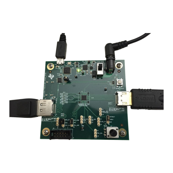
DP159RSBEVM Board
2
DP159RSBEVM Block Diagram
3
Register Status / Control Tab
4
Eye Scan Tab
5
HDMI Input Connectors
..................................................................................................................
6
7
HDMI TX Connector
8
DP159RSBEVM Select Options
........................................................................................................................
9
10
1.1- and 3.3-V Regulators
...................................................................................................................
11
12
13
14
15
16
Layer 5 (GND)
2
I
C is a trademark of NXP.
All other trademarks are the property of their respective owners.
SLLU224 - August 2015
Submit Documentation Feedback
................................................................................................
.....................................................................................
.............................................................................................
.......................................................................................................
........................................................................................................
.................................................................................................................
..............................................................................................
.....................................................................................
2
2
................................................................................................
............................................................................................................
........................................................................................................
..........................................................................................................
......................................................................................................
...........................................................................................
..............................................................................................
................................................................................................................
...................................................................................................
.......................................................................................................
..........................................................................................
................................................................................................
...............................................................................................................
..............................................................................................................
............................................................................................................
............................................................................................................
..............................................................................................................
Copyright © 2015, Texas Instruments Incorporated
DP159RSB Evaluation Module
Contents
.......................................................................
...............................................................................
............................................................................
....................................................
List of Figures
User's Guide
SLLU224 - August 2015
DP159RSB Evaluation Module
2
2
2
2
3
3
4
4
4
5
6
6
7
8
8
8
9
11
18
3
3
7
8
11
12
13
14
15
16
17
18
18
19
19
20
1
Advertisement
Table of Contents

Related Manuals for Texas Instruments DP159RSB


Summary of Contents for Texas Instruments DP159RSB
-
Page 1: Table Of Contents
......................Layer 4 (Power) ......................Layer 5 (GND) C is a trademark of NXP. All other trademarks are the property of their respective owners. SLLU224 – August 2015 DP159RSB Evaluation Module Submit Documentation Feedback Copyright © 2015, Texas Instruments Incorporated... - Page 2 Standard HDMI source connector (connects to sink) • DC power regulators • C™ programming interface for external I C host connection • USB interface (I C utility available) DP159RSB Evaluation Module SLLU224 – August 2015 Submit Documentation Feedback Copyright © 2015, Texas Instruments Incorporated...
- Page 3 TMDS_D1P/N DP159 IN2P/N TMDS_D0P/N (40-Pin RSB) IN3P/N TMDS_CLKP/N AUXP/N DDC_SCL/SDA 100-Ω differential impedance for HDMI and DP differential pairs. Figure 2. DP159RSBEVM Block Diagram SLLU224 – August 2015 DP159RSB Evaluation Module Submit Documentation Feedback Copyright © 2015, Texas Instruments Incorporated...
-
Page 4: Hardware Description
Alternately, it is possible to power the EVM by connecting a USB Micro cable from J13 to a USB host and setting SW2 to position 3. DP159RSB Evaluation Module SLLU224 – August 2015 Submit Documentation Feedback Copyright © 2015, Texas Instruments Incorporated... -
Page 5: Jumper Configuration
• Fixed EQ at 7.5 dB, when I2C_EN = L NC for adaptive EQ PRE_SEL JP 1-2 for –5 dB JP 2-3 JP 2-3 for –2.5 dB NC for 0 dB SLLU224 – August 2015 DP159RSB Evaluation Module Submit Documentation Feedback Copyright © 2015, Texas Instruments Incorporated... -
Page 6: Component Population Configuration
DP159RSBEVM. This mode allows the DDC lines to be routed around the DP159RSB, but remain connected to the DP159RSB on the sink side to allow the DP159RSB to snoop the DDC traffic. This snoop mode is enabled by default on the DP159RSB REV B1 EVMs. -
Page 7: Local I C Access Through Usb Interface Via Tusb3410
USB connection and confirm that the driver is loaded in Device Manager. It may take a moment for the USB driver to load, if the DP159RSB does not appear, hit the Refresh button. This tab can be used to read and write the status and control registers of the device. -
Page 8: Rsadj Potentiometer
5. Video output on HDMI sink should be observed. References 1. DP159 Data Sheet Aardvark Adapter User Manual 3. High-Definition Multimedia Interface Specification Version 1.4b. 4. High-Definition Multimedia Interface Specification Version 2.0. DP159RSB Evaluation Module SLLU224 – August 2015 Submit Documentation Feedback Copyright © 2015, Texas Instruments Incorporated... -
Page 9: Evm Bill Of Materials
P1 - DNI HDMI_IN CON_HDMI_RT_19_0p50mm Molex 471510001 HDMI_OUT CON_HDMI_RT_19_0p50mm Molex 471510001 Q1,Q2 FDV301N_NFET_8 SOT23 Fairchild FD301N Semiconductor R1,R2,R3,R4,R6,R7,R8,R9 R10,R11,R99,R100,R101,R1 R12,R27,R81 100K R33,R105,R106,R107,R108, R109,R110,R111,R112,R124 ,R125,R126,R136,R140, R141 R28,R29,R45,R46,R58,R59 SLLU224 – August 2015 DP159RSB Evaluation Module Submit Documentation Feedback Copyright © 2015, Texas Instruments Incorporated... - Page 10 TPS62150ARGTT TPS61240 6DRV TPS61240DRVT TPS74201RGWT RGW20 TPS74201RGWT TUSB3410 LQFP32 TUSB3410VF 24LC256 8SOIC CAT24C256W Semiconductor TPD2E001 drl_5pin TPD2E001 12 MHz Crystal ECX-32 ECS Inc. ECS-120-20-33-TR DP159RSB Evaluation Module SLLU224 – August 2015 Submit Documentation Feedback Copyright © 2015, Texas Instruments Incorporated...
-
Page 11: Evm Schematics
HDMI_CEC_SNK PAGE2,4 DP_SCL_SRC AUX_p (SCL) SCL_SRC PAGE2,3 GND6 DP_SDA_SRC SDA_SRC PAGE2,3 AUX_n (SDA) HPD_SRC DP_PWR_RTN DP_PWR Display_Port_Connector_Sink_0 DISPLAYPORT IN Figure 5. HDMI Input Connectors SLLU224 – August 2015 DP159RSB Evaluation Module Submit Documentation Feedback Copyright © 2015, Texas Instruments Incorporated... -
Page 12: Dp159Rsb
Pop R131, no pop R129, R130 for HPD on No pop R131, pop R129, R130 for HPD snoop only PAGE5 PRE_SEL PAGE5 EQ_SEL_A0 VSADJ PAGE5 Figure 6. DP159RSB DP159RSB Evaluation Module SLLU224 – August 2015 Submit Documentation Feedback Copyright © 2015, Texas Instruments Incorporated... - Page 13 OUT_CLKN PAGE3 HDMI_CEC_SNK PAGE2 SPDIF_IN PAGE2 SCL_SNK PAGE3 SDA_SNK PAGE3 HPD_SNK PAGE3 HDMI_OUT LP13 HDMI OUT LP12 LP11 LP10 Figure 7. HDMI TX Connector SLLU224 – August 2015 DP159RSB Evaluation Module Submit Documentation Feedback Copyright © 2015, Texas Instruments Incorporated...
- Page 14 OUT_CLKN PAGE3 HDMI_CEC_SNK PAGE2 SPDIF_IN PAGE2 SCL_SNK PAGE3 SDA_SNK PAGE3 HPD_SNK PAGE3 HDMI_OUT LP13 HDMI OUT LP12 LP11 LP10 Figure 8. DP159RSBEVM Select Options DP159RSB Evaluation Module SLLU224 – August 2015 Submit Documentation Feedback Copyright © 2015, Texas Instruments Incorporated...
- Page 15 HDMI_SEL#/TEST/A1 EQ_SEL_A0 PAGE3 SLEW_CTL PAGE3 HDMI_SEL#_TEST_A1 PAGE3 EQ_SEL_LO SLEW_CTL_LO HDR3X1 M .1 HDR3X1 M .1 HDR3X1 M .1 0402 0402 0402 Figure 9. Reset SLLU224 – August 2015 DP159RSB Evaluation Module Submit Documentation Feedback Copyright © 2015, Texas Instruments Incorporated...
- Page 16 OUT1 OUT2 10uF OUT3 4.7K BIAS OUT4 0402 1.87K EN1P2 0402 10uF FB_1PT2V 0.01uF SS1P2 TPS74201RGWT 4.99K 0402 Figure 10. 1.1- and 3.3-V Regulators DP159RSB Evaluation Module SLLU224 – August 2015 Submit Documentation Feedback Copyright © 2015, Texas Instruments Incorporated...
-
Page 17: Reset
SCL_CTL_USB P3_3 0402 PAGE5 SDA_CTL_USB P3_4 24LC256 WAKEUP R121 R101 VREGEN 0402 SUSP BOARD_3P3V RESET R103 TUSB3410 0402 RSTIn 1 uF Figure 11. TUSB3410 SLLU224 – August 2015 DP159RSB Evaluation Module Submit Documentation Feedback Copyright © 2015, Texas Instruments Incorporated... -
Page 18: Layer 1 (Top)
EVM Layout www.ti.com EVM Layout Figure 12 through Figure 17 illustrate the DP159RSBEVM PCB layouts. Figure 12. Layer 1 (Top) Figure 13. Layer 2 (GND) DP159RSB Evaluation Module SLLU224 – August 2015 Submit Documentation Feedback Copyright © 2015, Texas Instruments Incorporated... -
Page 19: Layer 3 (Power)
EVM Layout www.ti.com Figure 14. Layer 3 (Power) Figure 15. Layer 4 (Power) SLLU224 – August 2015 DP159RSB Evaluation Module Submit Documentation Feedback Copyright © 2015, Texas Instruments Incorporated... - Page 20 EVM Layout www.ti.com Figure 16. Layer 5 (GND) Figure 17. Layer 6 (Bottom) DP159RSB Evaluation Module SLLU224 – August 2015 Submit Documentation Feedback Copyright © 2015, Texas Instruments Incorporated...
- Page 21 STANDARD TERMS AND CONDITIONS FOR EVALUATION MODULES Delivery: TI delivers TI evaluation boards, kits, or modules, including any accompanying demonstration software, components, or documentation (collectively, an “EVM” or “EVMs”) to the User (“User”) in accordance with the terms and conditions set forth herein. Acceptance of the EVM is expressly subject to the following terms and conditions.
- Page 22 FCC Interference Statement for Class B EVM devices NOTE: This equipment has been tested and found to comply with the limits for a Class B digital device, pursuant to part 15 of the FCC Rules. These limits are designed to provide reasonable protection against harmful interference in a residential installation.
- Page 23 【無線電波を送信する製品の開発キットをお使いになる際の注意事項】 開発キットの中には技術基準適合証明を受けて いないものがあります。 技術適合証明を受けていないもののご使用に際しては、電波法遵守のため、以下のいずれかの 措置を取っていただく必要がありますのでご注意ください。 1. 電波法施行規則第6条第1項第1号に基づく平成18年3月28日総務省告示第173号で定められた電波暗室等の試験設備でご使用 いただく。 2. 実験局の免許を取得後ご使用いただく。 3. 技術基準適合証明を取得後ご使用いただく。 なお、本製品は、上記の「ご使用にあたっての注意」を譲渡先、移転先に通知しない限り、譲渡、移転できないものとします。 上記を遵守頂けない場合は、電波法の罰則が適用される可能性があることをご留意ください。 日本テキサス・イ ンスツルメンツ株式会社 東京都新宿区西新宿6丁目24番1号 西新宿三井ビル 3.3.3 Notice for EVMs for Power Line Communication: Please see http://www.tij.co.jp/lsds/ti_ja/general/eStore/notice_02.page 電力線搬送波通信についての開発キットをお使いになる際の注意事項については、次のところをご覧くださ い。http://www.tij.co.jp/lsds/ti_ja/general/eStore/notice_02.page SPACER EVM Use Restrictions and Warnings: 4.1 EVMS ARE NOT FOR USE IN FUNCTIONAL SAFETY AND/OR SAFETY CRITICAL EVALUATIONS, INCLUDING BUT NOT LIMITED TO EVALUATIONS OF LIFE SUPPORT APPLICATIONS.
- Page 24 Notwithstanding the foregoing, any judgment may be enforced in any United States or foreign court, and TI may seek injunctive relief in any United States or foreign court. Mailing Address: Texas Instruments, Post Office Box 655303, Dallas, Texas 75265 Copyright © 2015, Texas Instruments Incorporated...
- Page 25 IMPORTANT NOTICE Texas Instruments Incorporated and its subsidiaries (TI) reserve the right to make corrections, enhancements, improvements and other changes to its semiconductor products and services per JESD46, latest issue, and to discontinue any product or service per JESD48, latest issue.
- Page 26 Mouser Electronics Authorized Distributor Click to View Pricing, Inventory, Delivery & Lifecycle Information: Texas Instruments DP159RSBEVM...
Need help?
Do you have a question about the DP159RSB and is the answer not in the manual?
Questions and answers