
Related Manuals for Fronius PlasmaModule 10


Summary of Contents for Fronius PlasmaModule 10
-
Page 1: Operating Instructions
TÄYDELLISTÄ HITSAUSTA PLASMAMODULE 10 / Operating Instructions / Spare Parts List v.01/2012 ENG... - Page 3 Read the manual carefully and you will soon be familiar with all the many great features of your new Fronius product. This really is the best way to get the most out of all the advantages that your machine has to offer.
-
Page 5: Safety Rules
Safety rules DANGER! “DANGER!” indicates an imminently hazardous situation which, if not avoided, will result in death or serious injury. This signal word is to be limited to the most extreme situations. This signal word is not used for property damage hazards unless personal injury risk appropriate to this level is also involved. -
Page 6: Ambient Conditions
General remarks Any malfunctions which might impair machine safety must be eliminated (continued) immediately - meaning before the equipment is next switched on. It’s your safety that’s at stake! Utilisation for The machine may only be used for jobs as defined by the “Intended intended purpose purpose”. - Page 7 Obligations of Before starting work, all persons to be entrusted with carrying out work with personnel (or on) the machine shall undertake to observe the basic regulations on workplace safety and accident prevention to read the sections on “safety rules” and the “warnings” contained in this manual, and to sign to confirm that they have understood these and will comply with them.
- Page 8 Protection for “Protective clothing” also includes: yourself and protecting your eyes and face from UV rays, heat and flying sparks with other persons an appropriate safety shield containing appropriate regulation filter glass (continued) wearing a pair of appropriate regulation goggles (with sideguards) behind the safety shield wearing stout footwear that will also insulate even in wet conditions protecting your hands by wearing appropriate gloves (electrically insula-...
- Page 9 Hazards from The harmfulness of the welding fumes will depend on e.g. the following noxious gases components: and vapours the metals used in and for the workpiece (continued) the electrodes coatings cleaning and degreasing agents and the like For this reason, pay attention to the relevant Materials Safety Data Sheets and the information given by the manufacturer regarding the components listed above.
- Page 10 Hazards from Do not loop any cables or other leads around your body or any part of your mains and weld- body. ing current (continued) Never immerse the welding electrode (rod electrode, tungsten electrode, welding wire, ...) in liquid in order to cool it, and never touch it when the power source is ON.
- Page 11 Stray welding When using current supply distributors, twin head wire feeder fixtures etc., currents please note the following: The electrode on the unused welding torch/welding (continued) tongs is also current carrying. Please ensure that there is sufficient insula- ting storage for the unused welding torch/tongs. In the case of automated MIG/MAG applications, ensure that only insulated filler wire is routed from the welding wire drum, large wirefeeder spool or wirespool to the wirefeeder.
- Page 12 EMI Precautions Electromagnetic fields may cause as yet unknown damage to health. Effects on the health of persons in the vicinity, e.g. users of heart pace- makers and hearing aids Users of heart pacemakers must take medical advice before going anywhere near welding equipment or welding workplaces Keep as much space as possible between welding cables and head/body of welder for safety reasons...
- Page 13 Particular danger When hoisting the machines by crane, only use suitable manufacturer- spots supplied lifting devices. (continued) Attach the chains and/or ropes to all the hoisting points provided on the suitable lifting device. The chains and/or ropes must be at an angle which is as close to the vertical as possible.
- Page 14 Safety precauti- A machine that topples over can easily kill someone! For this reason, always ons at the instal- place the machine on an even, firm floor in such a way that it stands firmly. lation site and An angle of inclination of up to 10° is permissible. when being transported Special regulations apply to rooms at risk from fire and/or explosion.
- Page 15 Safety precauti- If any damage occurs in cases where other coolants have been used, the ons in normal manufacturer shall not be liable for any such damage, and all warranty operation claims shall be null and void. (continued) Under certain conditions, the coolant is flammable. Only transport the coolant in closed original containers, and keep it away from sources of ignition.
- Page 16 Safety markings Equipment with CE-markings fulfils the basic requirements of the Low- Voltage and Electromagnetic Compatibility Guideline (e.g. relevant product standards according to EN 60 974). . Equipment marked with the CSA-Test Mark fulfils the requirements made in the relevant standards for Canada and the USA. Data security The user is responsible for the data security of changes made to factory settings.
-
Page 17: Control Panel
Second level of Setup menu Setup menu level 2 (2nd) Flow monitoring Correction - Gas correction Setting - Country-specific setting (Standard / USA) Ignition Time-Out - Time until safety cut-out following an abortive ignition attempt Arc - Arc break watchdog Fronius International GmbH, www.fronius.com... -
Page 19: Table Of Contents
Connecting the interconnecting hosepack to the TIG power source ............13 Connecting the plasma welding torch ....................14 Connecting the shielding gas and plasma gas ..................15 Connecting PlasmaModule 10 and TIG power source to the robot control ..........15 Commissioning ............................16 General remarks ............................ 16 Commissioning ............................ - Page 20 Care, maintenance and disposal ......................... 28 General remarks ............................ 28 Every start-up ............................28 Every 2 months ............................28 Every 6 months ............................28 Disposal ..............................28 Configuration examples ..........................29 „Manual mode“ configuration ......................... 29 „Manual mode“ configuration - List of components ................30 „Robot mode“...
-
Page 21: General Remarks
General remarks Device concept The digital PlasmaModule 10 can be used with all TIG power sources from Fronius. Together with an appropriate power source, a cooling unit and a water-cooled plasma torch, it allows plasma welding processes to be carried out. -
Page 22: The Principle Of Plasma Welding
Power sources PlasmaModule 10 can be operated with the following power sources: for plasma wel- MagicWave 4000 / 5000 ding MagicWave 2600 / 2600 CEL / 3000 TransTig 2600 / 2600 CEL / 3000 TransTig 4000 / 5000 NOTE! Select the appropriate cooling unit for the existing plasma welding torch and the application. -
Page 23: Advantages Of Plasma Welding Over Tig Welding
Impossible for the tungsten electrode to dip into the weld pool Longer torch service life (with optimum torch cooling) Application areas The digital PlasmaModule 10 is used in automated and manual applications, for example: in the automotive and component supply industry, in the manufacture of special vehicles and construction plant... -
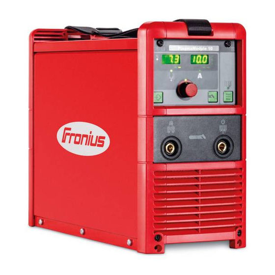
Page 24: Controls And Connections
You should not use the functions described until you have thoroughly read and understood the following documents: these Operating Instructions all the operating instructions for the system components, especially the safety regulations Housing front panel (16) (15) (14) (13) (12) (10) (11) Fig. 05 PlasmaModule 10 - Front panel... - Page 25 Housing front (1) Left digital display panel (2) Left unit display (continued) Either CFH or l/min appears in the Setup menu depending on the country setting (3) Right digital display (4) Right unit display Either CFH or l/min appears in the Setup menu depending on the country setting (5) Parameter unit display Either % or s appears depending on which parameter is chosen in the Setup menu (6) Pilot flow LED...
-
Page 26: Housing Rear Panel
(18) (19) (17) (20) Fig. 06 PlasmaModule 10 - Rear panel (17) LocalNet connection Standard connection socket for system add-ons (e.g. robot interface ROB 3000 or ROB 4000) (18) Plasma gas connection including supply pressure regulator; max. supply pressure 9 bar (130 psi) -
Page 27: Before Commissioning
Utilisation in The digital PlasmaModule 10 is intended to be used only in conjunction with a suitable accordance with TIG power source and a suitable plasma torch (e.g. Fronius PTW 1500). -
Page 28: Generator-Powered Operation
Details of the mains voltage tolerance are given in the section “Technical data”. Digital plasma The digital PlasmaModule 10 is fitted with a digital plasma gas regulator as standard. gas control WARNING! Plasma gas is colourless and odourless, is hazardous to health and can cause asphyxiation. -
Page 29: Installation
“O” position, the machine is unplugged from the mains. CAUTION! Falling equipment can cause injury. Make sure PlasmaModule 10 and the PlasmaModule holder stand firmly. Set up the individual components of the plasma welding system according to the intended application (see also the section „Configuration examples“) -
Page 30: Connecting The Plasma Welding Torch
Fig. 08 Connecting the interconnecting hosepack to the TIG power source TransTig 4000 / 5000 and cooling unit FK 4000 R Connecting the plasma welding torch Fig. 09 Connecting the plasma welding torch to PlasmaModule 10 and the PlasmaModule holder... -
Page 31: Connecting The Shielding Gas And Plasma Gas
Never take plasma gas and shielding gas from one and the same gas cylinder. Connect the plasma gas to the plasma gas connection of PlasmaModule 10 (on the rear of the unit), working pressure approx. 6 - 8 bar (86.99 - 115.99 psi.) -
Page 32: Commissioning
1 - 2.5 mm or 0.04 - 0.1 in.) with an adjusting gauge Turn the main switch of the power source to the „I“ position Connect PlasmaModule 10 to the mains and turn the main switch to the „I“ position Important! The PlasmaModule 10 must reach a certain operating temperature before it can regulate the gas accurately. -
Page 33: Plasma Welding Process
Plasma welding I (A) process Welding current t (s) Gas (l/min) Shielding gas t (s) I (A) Pilot flow t (s) Gas (l/min) Plasma gas t (s) -
Page 34: The Setup Menu
The Setup menu General remarks The Setup menu makes it easy to adapt the parameters saved in the unit to different types of task: The plasma gas supply parameters are set in the Gas Setup. The Setup menu contains parameters which have an immediate effect on the plasma process. -
Page 35: Setup Menu
3,0 - 30,0 Factory setting Factory - for resetting PlasmaModule 10 Press and hold the Store button for 2 s to reset the machine to the factory settings. If „PrG“ appears on the display, the parameters of the PlasmaModule are reset to the factory settings. - Page 36 Setup menu level Select parameters by pressing the Start / Stop button 2 (2nd) (continued) Change the parameter values by using the adjusting dial To exit Setup menu level 2: press the Store button twice press once = return to Setup menu, „2nd“ parameter press twice = return to normal mode Parameters for machine pre-sets Flow monitoring...
-
Page 37: Correction Factors
Correction fac- Plasma gas Composition DIN EN 439 Gas min. tors I1 100 % Ar 1.76 0.2 l I3 Ar 50 % He 3.78 0.3 l I3 Ar 15 % He 1.94 0.4 l I3 Ar 25 % He 2.70 0.2 l I3 Ar 30 % He 2.72... -
Page 38: Signals For Robot Welding
Signals for robot welding General remarks Robot operation of PlasmaModule 10 requires a robot interface. PlasmaModule 10 can be controlled via the following interfaces: Robot interface ROB 3000 Robot interface ROB 4000 Field bus Overview Signal I / O ROB 3000... -
Page 39: Signal Waveform
Signals for robot Power source ready welding The “Power source ready” signal remains on as long as PlasmaModule 10 is ready to (continued) weld. Welding current real value Via the „Welding current real value“ signal, the actual plasma gas value is indicated by a voltage of 0 - 10 V on the analog output. -
Page 40: Important Information For Robot Operation
Important infor- WARNING! Risk of injury and damage if welding starts unexpectedly. The “Arc mation for robot on” signal must not be set while the error is being rectified, otherwise welding operation will start as soon as the error is fixed. NOTE! If the connection between the power source and the robot interface goes down, all digital and analog output signals on the robot interface will be set to “0”. -
Page 41: Troubleshooting
Troubleshooting General remarks The digital PlasmaModule 10 is equipped with an intelligent safety system that does not require fuses. After a possible malfunction has been remedied, PlasmaModule 10 can be put back into normal operation again without any fuses having to be changed. - Page 42 Service codes no | IGn displayed Cause: „Ignition time-out“ function is active: No current started flowing before the (continued) end of the time specified in the Setup menu. The safety cut-out of Plasma- Module 10 has tripped. Remedy: Repeatedly press the Start / Stop button; clean the workpiece surface; if necessary, in „Setup menu level 2“...
-
Page 43: Troubleshooting
Service codes Err | 70.4 displayed Cause: Control valve faulty (continued) Remedy: Replace control valve Err | 70.5 Cause: Control valve not found Remedy: Check connections of the signal cable for the control valve Troubleshooting No function Mains switch is ON, but indicators are not lit up Cause: No connection to the mains Remedy:... -
Page 44: Care, Maintenance And Disposal
Care, maintenance and disposal General remarks Under normal operating conditions, PlasmaModule 10 requires only a minimum of care and maintenance. However, it is vital to observe some important points to ensure the plasma welding system remains in a usable condition for many years. -
Page 45: Configuration Examples
Configuration examples „Manual mode“ configuration Plasma gas (70) (60) (61) (50) (40) (80) Shielding gas (90) (30) (20) (10) (11) Fig. 10 „Manual mode“ configuration: Plasma welding system for manual use... -
Page 46: Manual Mode" Configuration - List Of Components
PlasmaModule holder installation set (61) Flow watchdog installation set PM 10 (70) PlasmaModule 10 (80) Plasma manual welding torch PTW 1500 F++ / FG / UD / 4 m (90) Grounding (earthing) cable 50 mm² / 4 m / 400 A / Plug 50 mm²... -
Page 47: Robot Mode" Configuration
„Robot mode“ configuration (91) (82) (90) Plasma gas (70) (71) (80) (100) (101) (60) (81) (113a) (50) (40) (110) (111) Shielding gas (112) (40a) (113) (120) (121) (32) (30) (31) (140) (130) (131) (20) (10) Robot control Fig. 11 „Robot mode“ configuration: Plasma welding system for automated use... -
Page 48: Robot Mode" Configuration - List Of Components
(80) Hot wire power source TransPocket 1500 RC HD (81) Grounding (earthing) cable 25 mm² / 6 m / hot wire (82) Connecting cable for TP 1500 RC HD (90) PlasmaModule 10 (91) Remote control cable 10-pole, 10 m (100) PlasmaModule holder installation set... -
Page 49: Technical Data
Technical data General remarks NOTE! Inadequately dimensioned electrical installations can lead to serious damage. The mains lead and its fuse protection must be rated accordingly. The technical data shown on the rating plate shall apply. Technical data Mains voltage 230 V Mains voltage tolerance -20% / +15% Mains fuse protection (slow-blow) -
Page 50: Exploded View
PlasmaModule 10 4,075,146 AM2,0201,1327 43,0004,0519 45,0200,1151 43,0004,1993 - US 42,0001,3541 - US 43,0002,0295 42,0300,0648 44,0001,1299 32,0405,0183 44,0001,1300 43,0004,2650 43,0001,1232 42,0409,3124 42,0401,0867 BE2,0201,1329 40,0001,0310 - * 12,0405,0365 42,0407,0273 33,0005,4142 42,0405,0421 41,0003,0203 43,0001,0600 43,0001,1272 33,0010,0326 43,0001,1271 43,0001,1273 12,0405,0365 43,0001,3293 41,0012,0033 42,0406,0315 42,0406,0093... - Page 51 43,0001,1138 42,0405,0420 4,070,960,Z - UST2C 41,0012,0080 4,070,812,Z - HFF22 43,0004,1122 - 26pol. PlasmaModule 10 Ersatzteilliste / Spare parts list / Listes de pièces de rechange / Lista de repuestos / Lista de pecas sobresselentes / Lista dei Ricambi el_fr_st_pl_01118 032006...
- Page 52 Maahantuonti ja myynti: Pronius Oy Keisarinviitta 20 B 33960 Pirkkala +358 (0)44 200 9060 info@pronius.fi www.pronius.fi...
Need help?
Do you have a question about the PlasmaModule 10 and is the answer not in the manual?
Questions and answers