
Related Manuals for Fronius TransTig 1750 Puls


Summary of Contents for Fronius TransTig 1750 Puls
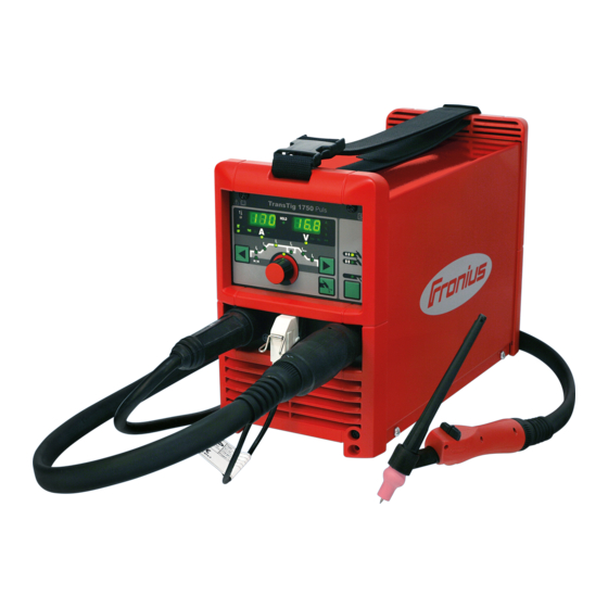
- Page 1 / Battery Charging Systems / Welding Technology / Solar Electronics Operating Instructions TransTig 1750 Puls TIG Power source 42,0426,0095,EN 007-08112012...
- Page 3 Thank you for the trust you have placed in our company and congratulations on buying this high-quality Fronius product. These instructions will help you familiarise yourself with the product. Reading the instructions carefully will enable you to learn about the many different features it has to offer.
-
Page 5: Table Of Contents
Contents Safety rules ..............................Explanation of safety symbols ......................General ..............................Intended purpose ..........................Environmental conditions........................Obligations of the operator........................Obligations of personnel ........................Mains connection ..........................Protecting yourself and others ......................Danger from toxic gases and vapours ....................Danger from flying sparks ........................Risks from mains current and welding current.................. - Page 6 Safety..............................General ..............................Connecting the gas cylinder........................Establishing a ground (earth) connection to the workpiece ..............Connecting the welding torch........................ Welding TIG modes ..............................Safety..............................Symbols and their explanations ......................2-step mode ............................Spot welding ............................4-step mode ............................Special 4-step: variant 1 ........................Overloading of the tungsten electrode .......................
- Page 7 Power source ............................Care, maintenance and disposal ....................... General ..............................Safety..............................At every start-up............................ Every 2 months ............................. Every 6 months ............................. Disposal ..............................Appendix Technical data............................Special voltages............................ TransTig 1750 Puls..........................Spare parts list ............................................................Circuit diagram............................................................
-
Page 9: Safety Rules
Safety rules Explanation of DANGER! indicates immediate and real danger. If it is not avoided, death or se- safety symbols rious injury will result. WARNING! indicates a potentially dangerous situation. Death or serious injury may result if appropriate precautions are not taken. CAUTION! indicates a situation where damage or injury could occur. -
Page 10: Intended Purpose
Intended purpose The device is to be used exclusively for its intended purpose. The device is intended for the welding process described on the rating plate only. Any use above and beyond this purpose is deemed improper. The manufac- turer shall not be liable for any damage resulting from such improper use. Utilisation in accordance with the "intended purpose"... -
Page 11: Obligations Of Personnel
Obligations of Before using the device, all persons instructed to do so undertake: personnel to observe the basic instructions regarding safety at work and accident prevention to read these operating instructions, especially the "Safety rules" section and sign to confirm that they have understood them and will follow them. Before leaving the work area, ensure that people or property cannot come to any harm in your absence. -
Page 12: Danger From Toxic Gases And Vapours
protect eyes and face from UV rays, heat and sparks using a protective visor and regulation filter. wear regulation protective goggles with side protection behind the safety visor. wear stout footwear that provides insulation even in wet conditions. protect the hands with suitable gloves (electrically insulated and providing protection against heat). -
Page 13: Danger From Flying Sparks
Danger from fly- Flying sparks may cause fires or explosions. ing sparks Never weld close to flammable materials. Flammable materials must be at least 11 metres (35 ft) away from the arc, or alternatively covered with an approved cover. A suitable, tested fire extinguisher must be available and ready for use. Sparks and pieces of hot metal may also get into adjacent areas through small gaps or openings. -
Page 14: Meandering Welding Currents
Arrange for the mains and device supply to be checked regularly by a qualified electrician to ensure the PE conductor is functioning properly. The device must only be operated on a mains supply with a PE conductor and a socket with an earth contact. If the device is operated on a mains without a PE conductor and in a socket without an earth contact, this will be deemed gross negligence. -
Page 15: Emc Device Classifications
EMC device clas- Devices with emission class A: sifications are only designed for use in an industrial setting can cause conducted and emitted interference in other areas. Devices with emission class B: satisfy the emissions criteria for residential and industrial areas. This also applies to residential areas in which power is supplied from the public low-voltage grid. -
Page 16: Specific Hazards
Specific hazards Keep hands, hair, clothing and tools away from moving parts. For example: Fans Cogs Rollers Shafts Wirespools and welding wires Do not reach into the rotating cogs of the wire drive or into rotating drive com- ponents. Covers and side panels may only be opened/removed while maintenance or repair work is being carried out. -
Page 17: Danger From Shielding Gas Cylinders
If the wire-feed unit is attached to a crane holder during welding, always use a suitable, insulated wire-feed unit holder (MIG/MAG and TIG devices). If the device has a carrying strap or handle, this is intended solely for carrying by hand. The carrying strap is not to be used if transporting with a crane, forklift or other mechanical hoist. -
Page 18: Safety Measures At The Installation Location And During Transport
Safety measures A device that topples over can easily kill someone. Place the device on a solid, at the installation level surface in such a way that it remains stable location and dur- The maximum permissible slope is 10°. ing transport Special regulations apply in rooms at risk of fire or explosion observe relevant national and international requirements. -
Page 19: Maintenance And Repair
Any safety devices that are not functioning properly must be repaired before switching on the device. Never bypass or disable protection devices. Before switching on the device, ensure that no one is likely to be endangered. Check the device at least once a week for obvious damage and proper functioning of safety devices. -
Page 20: Safety Inspection
Safety inspection The manufacturer recommends that a safety inspection of the device is per- formed at least once every 12 months. The manufacturer recommends that the power source be calibrated during the same 12-month period. A safety inspection should be carried out by a qualified electrician after any changes are made after any additional parts are installed, or after any conversions after repair, care and maintenance has been carried out... -
Page 21: Copyright
Copyright Copyright of these operating instructions remains with the manufacturer. The text and illustrations are all technically correct at the time of printing. We reserve the right to make changes. The contents of the operating instructions shall not provide the basis for any claims whatsoever on the part of the pur- chaser. -
Page 23: General Information
General information... -
Page 25: General
Application areas The power source is used for repair and maintenance tasks in production and manufactur- ing environments. Remote Control The power source TransTig 1750 Puls can be operated with the following remote controls: Operation TR 1200 TR 2000 TR 1300... -
Page 27: Control Elements And Connections
Control elements and connections... -
Page 29: Description Of The Control Panel
Description of the control panel General The key feature of the control panel is the logical way in which the controls are arranged. All the main parameters needed for day-to-day working can easily be: selected using the buttons altered with the adjusting dial shown during welding on the digital display Safety WARNING! Operating the equipment incorrectly can cause serious injury and... - Page 30 Item Designation Overtemperature indicator lights up if the power source overheats (e.g. because the duty cycle has been ex- ceeded). See the "Troubleshooting" section for more information. Special indicators Pulse indicator lights up when the F-P setup parameter has been set to a pulse frequen- Spot welding indicator lights up when the SPt setup parameter has been set to a spot welding time...
- Page 31 Item Designation kHz indicator lights up when the F-P setup parameter is selected if the value entered for the pulse frequency >= 1000 Hz Hz indicator lights up when: the F-P setup parameter is selected if the value entered for the pulse frequency <...
- Page 32 Item Designation (11) Welding parameters overview The welding parameters overview contains the most important welding parame- ters to be used when welding. The sequence of welding parameters follows a clothesline structure. Use the left and right Parameter Selection buttons to navi- gate within the welding parameters overview.
- Page 33 Item Designation (13) Welding current indicator to indicate the welding current for the parameters Starting current I Welding current I Reduced current I End current I Before welding commences, the left-hand digital display shows the set value. For and I , the right-hand digital display also shows the respective percentage of the welding current I After the start of welding, the welding parameter I...
-
Page 34: Key Combinations - Special Functions
Key combinations - special functions General The following functions can be executed by pressing buttons simultaneously or repeatedly. Displaying the Display software version: software version while pressing and holding the Mode button, press the left Parameter and operating Selection button. time The software version is now shown on the digital displays. -
Page 35: Connections, Switches And Mechanical Components
Connections, switches and mechanical components Connections, switches and me- chanical compo- nents TransTig 1750 Puls - front TransTig 1750 Puls - rear Item Designation (+) current socket with bayonet latch for connecting the grounding (earthing) cable when TIG welding the electrode cable or grounding (earthing) cable in MMA welding (depend-... -
Page 37: Installation And Commissioning
Installation and commissioning... -
Page 39: Minimum Equipment Needed For Welding Task
Minimum equipment needed for welding task General Depending on which welding process you intend to use, a certain minimum equipment lev- el will be needed in order to work with the power source. The welding processes and the minimum equipment levels required for the welding task are then described. -
Page 40: Before Installation And Commissioning
Before installation and commissioning Safety WARNING! Operating the equipment incorrectly can cause serious injury and damage. Do not use the functions described until you have thoroughly read and understood the following documents: these operating instructions all the operating instructions for the system components, especially the safe- ty rules Utilisation for in- The power source is intended exclusively for TIG and MMA welding. - Page 41 NOTE! The voltage delivered by the generator must never exceed the upper or lower limits of the mains voltage tolerance range. Details of the mains voltage tol- erance are given in the "Technical data" section.
-
Page 42: Start-Up
Start-up Safety WARNING! An electric shock can be fatal. If the machine is plugged into the mains electricity supply during installation, there is a high risk of very serious in- jury and damage. Do not carry out any work on the device unless the mains switch is in the "O"... -
Page 43: Connecting The Welding Torch
Connecting the Move the mains switch to the "O" position welding torch Plug the welding cable of the TIG torch into the (-) current socket and twist it clockwise to latch it in place Plug the control plug of the welding torch into the torch control connection and latch it in place NOTE! Do not use pure tungsten electrodes (colour-coded green). -
Page 45: Welding
Welding... -
Page 47: Tig Modes
TIG modes Safety WARNING! Operating the equipment incorrectly can cause serious injury and damage. Do not use the functions described until you have thoroughly read and understood the following documents: these operating instructions all the operating instructions for the system components, especially the safe- ty rules See the "The Setup menu"... -
Page 48: 2-Step Mode
down Downslope phase: the welding current is continuously lowered until it reaches the end- crater current End current phase: to prevent any local overheating of the base material due to heat build-ups towards the end of welding. This eliminates any risk of weld drop-through. End current time Spot welding time Gas post-flow time at maximum welding current... -
Page 49: 4-Step Mode
down 4-step mode Welding start-up with starting current I : pull back and hold the torch trigger Welding with main current I : release the torch trigger Lowering to end current I : pull back and hold the torch trigger End of welding: release the torch trigger IMPORTANT! For 4-step mode, the SFS setup parameter must be set to "OFF". - Page 50 down...
-
Page 51: Overloading Of The Tungsten Electrode
Overloading of the tungsten electrode Overloading of If the tungsten electrode is overloaded, the "Electrode overload" indicator on the the tungsten elec- control panel lights up. trode Possible causes of tungsten electrode overload: tungsten electrode diameter is too small main current value I set too high Remedy: use a tungsten electrode with a larger diameter... -
Page 52: Tig Welding
TIG welding Safety WARNING! Operating the equipment incorrectly can cause serious injury and damage. Do not use the functions described until you have thoroughly read and understood the following documents: these operating instructions all the operating instructions for the system components, especially the safe- ty rules WARNING! An electric shock can be fatal. -
Page 53: Preparations
End current I Unit % (of main current I Setting range 0 - 100 Factory settings Electrode diameter Unit Setting range OFF / 0.1 - 3.2 Factory settings Preparations Plug in the mains plug CAUTION! Risk of injury and damage from electric shock. As soon as the mains switch is in the "I"... -
Page 54: Igniting The Arc
Igniting the arc Igniting the arc HF ignition is activated when a time value has been set for the HFt setup parameter. using high fre- The HF ignition indicator lights up on the control panel. quency (HF ignition) Compared with touchdown ignition, HF ignition eliminates the risk of contamination of the tungsten electrode and the workpiece. -
Page 55: Touchdown Ignition
Tilt the torch back into the normal posi- tion Carry out welding Touchdown igni- If the HFt setup parameter is set to OFF, HF ignition is deactivated. The welding arc is ig- tion nited by touching the workpiece with the tungsten electrode. Procedure for igniting the arc using touchdown ignition: Place the gas nozzle down on the igni- tion location so that there is a gap of... -
Page 56: End Of Welding
Raise the welding torch and move it into its normal position The arc ignites. Carry out welding End of welding Depending on the set mode, finish welding by releasing the torch trigger Wait for the set gas post-flow and hold welding torch in position over the end of the weld seam... -
Page 57: Special Functions And Options
Special functions and options Arc break watch- If the arc breaks and no current starts to flow again within a time specified in the Setup dog function menu, the power source cuts out automatically. The service code "no | Arc" appears on the control panel. -
Page 58: Tacking Function
1/F-P down TIG pulsing - welding current curve Legend: Starting current Pulse frequency *) End current Duty cycle Upslope Ground current Downslope Main current Down *) (1/F-P = time interval between two pulses) Tacking function The power source has a tacking function. When a time period is specified for the tAC (tacking) setup parameter, the tacking function is assigned to the 2-step mode and 4-step mode. - Page 59 Starting current End current Upslope Downslope Down Main current IMPORTANT! The following points apply to the pulsed welding current: The power source automatically regulates the pulsing parameters as a function of the specified main current I There is no need to set any pulsing parameters The pulsed welding current begins: After the end of the starting current phase I With the upslope phase t...
-
Page 60: Mma Welding
MMA welding Safety WARNING! Operating the equipment incorrectly can cause serious injury and damage. Do not use the functions described until you have thoroughly read and understood the following documents: these operating instructions all the operating instructions for the system components, especially the safe- ty rules WARNING! An electric shock can be fatal. -
Page 61: Hotstart Function
the next time they are changed. This applies even if the power source is switched off and on again in the meantime. Start welding HotStart function To obtain optimum welding results, it will sometimes be necessary to adjust the HotStart function. - Page 62 The anti-stick function can be activated and deactivated in the "Setup menu: level 2" sec- tion.
-
Page 63: Setup Settings
Setup settings... -
Page 65: The Setup Menu
The Setup menu General The Setup menu provides easy access to expert knowledge in the power source and to additional functions. The Setup menu can be used to make simple adjustments of the weld- ing parameters to suit the various job settings. The following can be found in the Setup menu: Setup parameters that have an immediate effect on the welding process Setup parameters needed for making the preliminary settings on the welding system... -
Page 66: Shielding Gas Setup Menu
Shielding gas setup menu General The Shielding gas setup menu provides easy access to the shielding gas settings. Accessing the Shielding gas set- Press and hold the Mode button up menu Press the Gas test button The power source is now in the Shielding gas setup menu. The last welding parameter selected is displayed. - Page 67 The value set for G-H only applies if the maximum welding current really has been set. The actual value is derived from the present welding current. For a medium welding cur- rent, for example, the actual value will be half of the value set for G-H. IMPORTANT! The values set for the G-L and G-H setup parameters are added together.
-
Page 68: Tig Setup Menu
TIG setup menu Accessing the Press the Mode button to select 2-step mode or 4-step mode TIG setup menu Press and hold the Mode button Press the Parameter Selection button (right) The power source is now in the TIG setup menu. The last welding pa- rameter selected is displayed. - Page 69 Factory settings "ON" The pulsed welding current continues until the end of the tack- ing operation 0.1 - 9.9 s The set time begins with the upslope phase. After the end of the set time, welding continues at a constant current; any pulsing parameters that have been set are available.
- Page 70 Time starting - starting current time Unit Setting range OFF/0.01 - 9.9 Factory settings The starting current time t-S specifies the duration of the starting current phase Is. IMPORTANT! The t-S setup parameter only applies to 2-step mode. In 4-step mode, the duration of the starting current phase Is is controlled using the torch trigger.
-
Page 71: Tig Setup Menu: Level 2
TIG setup menu: level 2 Accessing the Accessing the TIG setup menu TIG setup menu: level 2 Select "2nd" welding parameter Press and hold the Mode button Press the Parameter Selection button (right) The power source is now in TIG set-up menu - level 2. The last welding parameter selected is displayed. - Page 72 NOTE! If there are problems with sensitive equipment in the immediate vicinity, increase the HFt parameter to a maximum of 0.4 s. The special HF ignition indicator remains lit as long as a value has been specified for the HFt parameter. If the HFt setup parameter is set to "OFF", no high-frequency ignition takes place at the start of welding.
-
Page 73: Rod Electrode Setup Menu
Rod electrode setup menu Accessing the Press the Mode button to select the MMA welding mode Rod electrode setup menu Press and hold the Mode button Press the Parameter Selection button (right) The power source is now in the Rod electrode setup menu. The last welding parameter selected is displayed. - Page 74 dYn - dynamic correction Unit Setting range 0 - 100 Factory settings soft, low-spatter arc harder, more stable arc To obtain optimum welding results, it will sometimes be necessary to adjust the arc-force dynamic. Functional principle: at the instant of droplet transfer or when a short circuit occurs, there is a momentary rise in amperage.
-
Page 75: Rod Electrode Setup Menu: Level 2
Rod electrode setup menu: level 2 Accessing the Accessing the Rod electrode setup menu Rod electrode setup menu level Select "2nd" welding parameter Press and hold the Mode button Press the Parameter Selection button (right) The power source is now in the Rod electrode setup menu: level 2. The last parameter selected is displayed. - Page 76 Unit Setting range OFF/5 - 90 Factory settings The arc length depends on the welding voltage. To end the welding process, it is usually necessary to significantly lift the rod electrode away from the workpiece. With the "Uco" parameter, the welding voltage can be limited to a value that makes it possible to end the welding process simply by lifting the rod electrode slightly.
-
Page 77: Troubleshooting And Maintenance
Troubleshooting and maintenance... -
Page 79: Troubleshooting
Troubleshooting General The power source is fitted with an intelligent safety system that allows fuses to be dis- pensed with entirely. After a possible malfunction or error has been remedied, the power source can be put back into normal operation again without any fuses having to be re- placed. -
Page 80: Power Source
Cause: Primary overcurrent Remedy: Contact After-Sales Service Power source Power source has no function Mains switch is on, but indicators are not lit up Cause: There is a break in the mains lead; the mains plug is not plugged Remedy: Check the mains supply lead, make sure that the mains plug is plugged in Cause:... - Page 81 Remedy: Change the gas cylinder Cause: Gas pressure regulator is faulty Remedy: Change the gas pressure regulator Cause: The gas hose is not fitted or is damaged Remedy: Fit/change the gas hose Cause: The welding torch is faulty Remedy: Change the welding torch Cause: Gas solenoid valve is faulty Remedy:...
-
Page 82: Care, Maintenance And Disposal
Care, maintenance and disposal General Under normal operating conditions, the power source requires only a minimum of care and maintenance. However, it is vital to observe some important points to ensure it remains in a usable condition for many years. Safety WARNING! An electric shock can be fatal. -
Page 83: Appendix
Appendix... -
Page 85: Technical Data
Technical data Special voltages The technical data on the rating plate applies to devices designed for special voltages. TransTig 1750 Mains voltage 1 x 230 V Puls Mains voltage tolerance -20 %/+15 % Mains frequency 50 / 60 Hz Mains fuse protection 16 A slow-blow Mains connection restrictions possible... -
Page 86: Spare Parts List
Spare parts list... -
Page 87: Circuit Diagram
Circuit diagram 230 V 50Hz +A4 FP22JOB +A1 NF +A4-X1 +A3-X13 +A3-X2 +A3-X19 - VALVE + VALVE +A3-X16 +A2 BPS1750 - FAN COMMON + FAN MAIN CURRENT PRIM / SEK CRATFILL CUR TORCH IDENTIF DOWN PRIM / SEK +A3-X8 +A3-X5 +A3-X12 +24 V TX L REMOTE... - Page 88 FRONIUS INTERNATIONAL GMBH Froniusplatz 1, A-4600 Wels, Austria Tel: +43 (0)7242 241-0, Fax: +43 (0)7242 241-3940 E-Mail: sales@fronius.com www.fronius.com www.fronius.com/addresses Under http://www.fronius.com/addresses you will find all addresses of our Sales & service partners and Locations...
Need help?
Do you have a question about the TransTig 1750 Puls and is the answer not in the manual?
Questions and answers