
Subscribe to Our Youtube Channel
Related Manuals for SIGMATEK CP 101


Summary of Contents for SIGMATEK CP 101
- Page 1 CP 101 S-DIAS CPU Module Instruction Manual Date of creation: 10.04.2014 Version date: 26.07.2023 Article number: 20-004-101-E...
- Page 2 (print, photocopy, microfilm or in any other process) without the express permission. We reserve the right to make changes in the content without notice. The SIGMATEK GmbH & Co KG is not responsible for technical or printing errors in the handbook and assumes no responsibility for damages that occur...
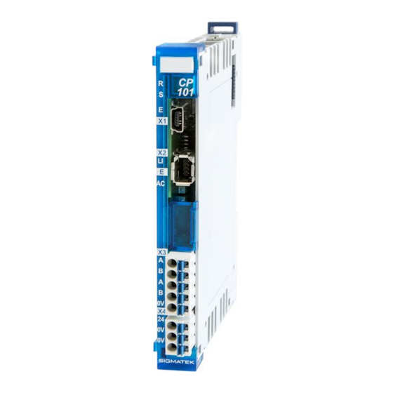
- Page 3 1 Ethernet 1 USB Device 1 CAN The S-DIAS CP 101 CPU module is a high-performance processor unit for the S-DIAS I/O modules. With the Ethernet and CAN bus interfaces, the module can be used for various applications. A zero-voltage protected RAM area is available, which is implemented by copying a data block from the DDR RAM to the NAND Flash.
-
Page 4: Table Of Contents
CP 101 S-DIAS CPU MODULE Contents Introduction ................5 Target Group/Purpose of this Operating Manual ...... 5 Important Reference Documentation ......... 5 Contents of Delivery ..............5 Basic Safety Directives ............6 Symbols Used ................6 Disclaimer ..................8 General Safety Directives ............9 Software/Training ............... - Page 5 S-DIAS CPU MODULE CP 101 Mechanical Dimensions ............18 Connector Layout ..............19 Status LEDs ................. 20 Connectors .................. 20 Applicable Connector Cables ............ 21 Applicable Connectors ............... 22 Label Field ................... 23 CAN Bus Setup ..............24 CAN Bus Station Number ............24 Number of CAN Bus Participants ..........
- Page 6 CP 101 S-DIAS CPU MODULE 14 Assembly/Installation ............37 14.1 Check Contents of Delivery ............37 14.2 Mounting ..................38 15 Transport/Storage ..............40 16 Storage ...................40 17 Maintenance ................41 17.1 Service ..................41 17.2 Repair ................... 41 18 Disposal ..................41 Page 4...
-
Page 7: Introduction
General knowledge of automation technology is required. Further help and training information, as well as the appropriate accessories can be found on our website www.sigmatek-automation.com. Our support team is happily available to answer your questions. Please see our website for our hotline number and business hours. -
Page 8: Basic Safety Directives
CP 101 S-DIAS CPU MODULE Basic Safety Directives Symbols Used The following symbols are used in the operator documentation for warning and danger messages, as well as informational notes: DANGER Danger indicates that death or serious injury will occur, if the specified measures are not taken. - Page 9 S-DIAS CPU MODULE CP 101 INFORMATION Information Provides important information on the product, handling or relevant sections of the documentation, which require attention. 26.07.2023 Page 7...
-
Page 10: Disclaimer
It does not guarantee properties under the warranty. Please thoroughly read the corresponding documents and this operating manual before handling a product. SIGMATEK GmbH & Co KG is not liable for damages caused through, non-compliance with these instructions or applicable regulations. -
Page 11: General Safety Directives
S-DIAS CPU MODULE CP 101 General Safety Directives The Safety Directives in the other sections of this operating manual must be observed. These instructions are visually emphasized by symbols. INFORMATION According to EU Directives, the operating manual is a component of a product. -
Page 12: Software/Training
CP 101 S-DIAS CPU MODULE CAUTION Handle the device with care and do not drop or let fall. Prevent foreign bodies and fluids from entering the device. The device must not be opened! Manipulez l’appareil avec précaution et ne le laissez pas tomber. -
Page 13: Standards And Directives
The product was constructed in compliance with the following European Union directives and tested for conformity. 3.1.1 EU Conformity Declaration EU Declaration of Conformity The product CP 101 conforms to the following European directives: • 2014/35/EU Low-voltage Directive • 2014/30/EU Electromagnetic Compatibility (EMC Directive) •... -
Page 14: Type Plate
CP 101 S-DIAS CPU MODULE Type Plate HW: Hardware version SW: Software version Page 12 26.07.2023... -
Page 15: Technical Data
The application must ensure that the actual time and date is set after the CPU start-up phase) INFORMATION The CP 101 can only supply the number of modules supported by the maximum output current (0.6 A) on the S-DIAS bus. 26.07.2023... -
Page 16: Standard Configuration
INFORMATION Problems can arise if a control is connected to an IP network, which contains modules that do not run on a SIGMATEK operating system. With such devices, Ethernet packets could be sent to the control with such a high frequency (i.e. broadcasts), that the high interrupt load could cause a real-time runtime error or runtime error. -
Page 17: S-Dias Bus Supply (Output)
S-DIAS CPU MODULE CP 101 5.3.2 S-DIAS Bus Supply (Output) Voltage supply from the S-DIAS +5 V Current consumption on the S-DIAS maximum 0.6 A bus (+5 V supply) Voltage supply from the S-DIAS +24 V Current consumption on the S-DIAS maximum 0.6 A... - Page 18 CP 101 S-DIAS CPU MODULE Page 16 26.07.2023...
-
Page 19: Miscellaneous
S-DIAS CPU MODULE CP 101 Miscellaneous Article number 20-004-101 Operating system Salamander Standard UL 508 (E247993) Approbations UL, cUL, CE Environmental Conditions Storage temperature -20 ... +85 °C Environmental temperature 0 ... +55 °C Humidity 0-95 %, non-condensing Installation altitude above sea level 0-2000 m without derating >... -
Page 20: Mechanical Dimensions
CP 101 S-DIAS CPU MODULE Mechanical Dimensions Page 18 26.07.2023... -
Page 21: Connector Layout
S-DIAS CPU MODULE CP 101 Connector Layout INFORMATION The GND supply (X4: Pin 2 and Pin 3) is internally bridged. Only one GND pin (pin 2 or pin 3) is required to power the module. The bridged connections may be used for further looping of the GND supply. -
Page 22: Status Leds
CP 101 S-DIAS CPU MODULE Status LEDs green from activation of the voltage supply until processing of the autoexec.lsl when the application is running (except when controlled through application differently) BLINKS In the CLI, while processing the autoexec.lsl until the application is... -
Page 23: Applicable Connector Cables
S-DIAS CPU MODULE CP 101 X2: Ethernet (Industrial Mini I/O) Function n.c. n.c. Applicable Connector Cables Ethernet Cable type Length Article number RJ45 on industrial Mini I/O Type 1, drag chain capable 0.5 m 16-911-005 16-911-010 1.5 m 16-911-015 16-911-020... -
Page 24: Applicable Connectors
CP 101 S-DIAS CPU MODULE Applicable Connectors Connectors: X1: USB 1.1 (Mini-B) (not included in delivery) X2: Industrial Mini I/O Plug Type 1 Lock Extended Version (not included in delivery) X3, X4: Connectors with spring terminals (included in delivery) The spring terminals are suitable connecting ultrasonically compacted (ultrasonically welded) strands. -
Page 25: Label Field
S-DIAS CPU MODULE CP 101 Label Field Manufacturer Weidmüller Type MF 10/5 CABUR MC NE WS Weidmüller article number 1854510000 Compatible printer Weidmüller Type Printjet Advanced 230V Weidmüller article number 1324380000 26.07.2023 Page 23... -
Page 26: Can Bus Setup
CP 101 S-DIAS CPU MODULE CAN Bus Setup This section explains how to correctly configure the CAN bus. The following parameters must first be set: Station number and data transfer rate. CAN Bus Station Number Each CAN bus station is assigned its own station number. With this station number, data can be exchanged with other stations connected to the bus. -
Page 27: Can Bus Termination
In a CAN bus system, both end modules must be terminated. This is necessary to avoid transmission errors caused by reflections in the line. If the CP 101 processor module is an end module, it can be terminated by placing a 120 resistor between CAN-A (Low) and CAN-B (High). -
Page 28: Strain Relief
CP 101 S-DIAS CPU MODULE Strain Relief INFORMATION The VARAN cable must be mounted close to the module (e.g. using a clamp)! No mechanical stress can be applied to the connection! Page 26 26.07.2023... -
Page 29: Process Diagram
S-DIAS CPU MODULE CP 101 10 Process Diagram 26.07.2023 Page 27... -
Page 30: Status And Error Messages
CP 101 S-DIAS CPU MODULE 11 Status and Error Messages Status and error messages are displayed in the LASAL Class software status test. Number Message Definition Cause/solution RUN RAM The user program is currently running in INFO RAM. The display is not affected. - Page 31 S-DIAS CPU MODULE CP 101 WATCHDOG The program was interrupted via the Possible Causes: watchdog logic. User program interrupts blocked over a longer period of time (STI command forgotten) Programming error in a hardware interrupt. INB, OUTB, INW, OUTW instructions used incorrectly.
- Page 32 CP 101 S-DIAS CPU MODULE PROG MEMO The CPU is currently programming the Info memory module. STOP BRKPT The CPU was stopped by a breakpoint Info in the program. CPU STOP stopped Info programming software. INT ERROR The CPU has triggered a false interrupt...
- Page 33 Info reinstalled. OS TOO LONG The operating system cannot be loaded; Restart; report error to SIGMATEK. too little memory. NO OPERATING Boot loader message. Restart; report error to SIGMATEK. SYSTEM No operating system found in RAM. SEARCH FOR OS The boot loader is searching for the Restart;...
- Page 34 FLOATING POINT An error has occurred during a floating- ERROR point operation. DIAS-RISC-ERROR Error from the Intelligent DIASMaster. Restart; report error to SIGMATEK. INTERNAL ERROR An internal error has occurred, all Restart; report error to SIGMATEK. applications are stopped. FILE ERROR An error has occurred during a file operation.
- Page 35 S-DIAS CPU MODULE CP 101 Solution: This depends on the cause S-DIAS ERROR A connection error with a S-DIAS Possible causes: module has occurred. real network does not match the project S-DIAS client is defective Solution: analyze logfile USER DEFINED 0 User-definable code.
- Page 36 CP 101 S-DIAS CPU MODULE C_SYNTAX_ERROR No specific error, recompile all project components and reload the project. C_NO_FILE_OPEN An attempt was made to open an unknown table. C_OUTOF_NEAR Memory allocation error C_OUT OF_FAR Memory allocation error C_INCOMAPTIBLE An object with the same name already exists but has a different class.
-
Page 37: Application Exceptions
S-DIAS CPU MODULE CP 101 12 Application Exceptions Do not store, modify or write on the Flash from the user program. 12.1 Data Breakpoint This CPU does not support the data breakpoint feature. 13 Wiring Guidelines The input filters, which suppress noise signals, allow operation in harsh environmental conditions. -
Page 38: Shielding
13.2 ESD-Protection Before any device is connected to or disconnected from the CP 101, the potential with ground should be equalized (by touching the control cabinet or ground terminal). This will allow the dissipation of electrostatic loads (caused by clothing/shoes). -
Page 39: Assembly/Installation
S-DIAS CPU MODULE CP 101 14 Assembly/Installation 14.1 Check Contents of Delivery Ensure that the contents of the delivery are complete and intact. See chapter Contents of Delivery. INFORMATION On receipt and before initial use, check the device for damage. If the device is damaged, contact our customer service and do not install the device in your system. -
Page 40: Mounting
CP 101 S-DIAS CPU MODULE 14.2 Mounting The S-DIAS modules are designed for installation into the control cabinet. To mount the modules a DIN-rail is required. The DIN rail must establish a conductive connection with the back wall of the control cabinet. The individual S-DIAS modules are mounted on the DIN rail as a block and secured with latches. - Page 41 S-DIAS CPU MODULE CP 101 Recommended minimum distances of the S-DIAS modules to the surrounding components or control cabinet wall: a, b, c … distances in mm (inches) 26.07.2023 Page 39...
-
Page 42: Transport/Storage
CP 101 S-DIAS CPU MODULE 15 Transport/Storage INFORMATION This device contains sensitive electronics. During transport and storage, high mechanical stress must therefore be avoided. For storage and transport, the same values for humidity and vibration as for operation must be maintained! Temperature and humidity fluctuations may occur during transport. -
Page 43: Maintenance
S-DIAS CPU MODULE CP 101 17 Maintenance INFORMATION During maintenance as well as servicing, observe the safety instructions from chapter 2 Basic Safety Directives. 17.1 Service This product was constructed for low-maintenance operation. 17.2 Repair INFORMATION In the event of a defect/repair, send the device with a detailed error description to the address listed at the beginning of this document. - Page 44 CP 101 S-DIAS CPU MODULE Documentation Changes Change date Affected Chapter Note page(s) 04.06.2014 7 Status- and Error Messages S-DIAS Error added 08.09.2014 1.3 Electrical Requirements Added Supply Voltage (UL) and notice in grey box 1.4 Miscellaneous Added Standard 22.01.2015...
- Page 45 S-DIAS CPU MODULE CP 101 20.09.2018 3 Connector Layout Note added 04.11.2020 10 Mounting Expansion functional ground connection 20.04.2023 3 Connector Layout Info box corrected 26.07.2023 Document General chapters added, design 26.07.2023 Page 43...
- Page 46 CP 101 S-DIAS CPU MODULE Page 44 26.07.2023...
Need help?
Do you have a question about the CP 101 and is the answer not in the manual?
Questions and answers