Table of Contents
Advertisement
Quick Links
Document changes and version status
Change date
Affected
page(s)
19.12.2013
12 to 12a
31.01.2018
5, 8, 9, 13
8
13
14
05.10.2018
11
1.3
C-DIAS SAFETY DIGITAL INPUT MODULE
Changes/expansions/corrections
Added Standard and Electrical requirements for UL table
Removed standard IEC 61508
Added amendments „Category 4" and „EN"
Added chapter „Conformity with EU Standards"
Added amendment „EN" (62061)
Added „Cat. 4"
Added unit 1/h on PFH
Changed value from 5.13 to 5.13E-09
Changed EMC resistance to 61000-6-2:2005
Note cable capacitance and cable resistance added
value
D
CSDI 162
Version
1.1
1.2
1.3
Page 1
Advertisement
Table of Contents

Related Manuals for SIGMATEK CSDI 162


Summary of Contents for SIGMATEK CSDI 162
- Page 1 C-DIAS SAFETY DIGITAL INPUT MODULE CSDI 162 Document changes and version status Change date Affected Changes/expansions/corrections Version page(s) 19.12.2013 12 to 12a Added Standard and Electrical requirements for UL table 31.01.2018 5, 8, 9, 13 Removed standard IEC 61508 Added amendments „Category 4“ and „EN“...
-
Page 2: Table Of Contents
12 Safety Conformity ....................13 Conformity with EU Standards ..................13 Functional safety standards ..................13 Safety-relevant parameters ..................13 Environmental conditions .................... 14 Miscellaneous ......................15 CSDI 162 Circuit ....................16 Page 2 05.10.2018... -
Page 3: Directory Of Illustrations
Fig. 1: Example of a minimum system for a safety-related control ........6 Fig. 2: CSDI 162 ........................8 Fig. 3: Mechanical dimensions ................... 10 Fig. 4: CSDI 162 circuit ....................... 16 Fig. 5 : Connector plug coding.................... 20 Fig. 6: Simplified status diagram ..................22 Fig. -
Page 4: Explanation Of Safety Symbols
Delivery Condition The individual SIGMATEK Safety components are delivered in specific hard and software configurations. Any change of this configuration that exceeds the options specified in this documentation, is unauthorized and invalidates the warranty from SIGMATEK GmbH & Co... -
Page 5: Test Signals For Cross-Circuit Detection
C-DIAS SAFETY DIGITAL INPUT MODULE CSDI 162 Test Signals for Cross-Circuit Detection The module sends pulses in cyclic time intervals to detect a crossed circuit in the outputs. When selecting the actuators, keep in mind that these pulses do not acti- vate the actuators or trigger any diagnostic messages. -
Page 6: The C-Dias Bus And Connector Layout
CSDI 162 C-DIAS SAFETY DIGITAL INPUT MODULE The C-DIAS bus and Connector Layout Signal Signal Signal CDIAS_/MS CDIAS_/RES ------ CDIAS_EE_A2 CDIAS_EE_CLK CDIAS_EE_DAT CDIAS_EE_A1 CDIAS_SYNC CDIAS_EE_IRQ CDIAS_EE_A0 CDIAS_RDY CDIAS_/DEN ------ CDIAS_/RD CDIAS_/WR ------ CDIAS_A6 CDIAS_A7 ------ CDIAS_A4 CDIAS_A5 ------ CDIAS_A2 CDIAS_A3... - Page 7 C-DIAS SAFETY DIGITAL INPUT MODULE CSDI 162 The minimal system of a safety-related control, formed as shown above, with a C-IPC a CMB 081 and a Safety CPU type CSCP 012. The safety-related application is found in the Safety CPU and can run independently of the C-IPC.
-
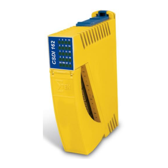
Page 8: C-Dias Safety Digital Input Module Csdi 162
TA and TB, to test inputs and detect cross-circuit errors (i.e. emergency stop). Fig. 2: CSDI 162 The Safety input module CSDI 162 is suited for use in systems with optional modules and interface variables in accordance with the system hand book version 1.5, sections 1.6, 7.1 and 7.2. -
Page 9: Designated Use
CSDI 162 Designated Use The CSDI 162 Safety module is designed for use in Safety-related applications and meets the required conditions for Safety operation in compliance with Perfo- mancelevel e (PL e), according to EN ISO 13849 and/or SIL 3 according to EN 62061. -
Page 10: Mechanical Dimensions
CSDI 162 C-DIAS SAFETY DIGITAL INPUT MODULE Mechanical Dimensions Fig. 3: Mechanical dimensions Page 10 05.10.2018... -
Page 11: Technical Data
C-DIAS SAFETY DIGITAL INPUT MODULE CSDI 162 Technical Data Input specifications The inputs are type 1 according to IEC/EN 61131 Number of … Input voltage +24 V DC Input voltage range Minimum +18 V Maximum +30 V Low: ≤ +5 V High: ≥... -
Page 12: Electrical Requirements
CSDI 162 C-DIAS SAFETY DIGITAL INPUT MODULE Electrical requirements The Safety modules' electrical supply must also be provided over the C-DIAS bus. A differ- ent type and method of supplying energy is not allowed. The C-DIAS bus system's external 24 V supply voltage must be generated by a PELV power supply. -
Page 13: Safety Conformity
C-DIAS SAFETY DIGITAL INPUT MODULE CSDI 162 Safety Conformity Conformity with EU Standards The module has been designed in accordance with the following European Union direc- tives: 2006/42/EG Machinery Directive 2014/30/EU EMC Directive 2011/65/EU RoHS Directive Functional safety standards EN/IEC 62061... -
Page 14: Environmental Conditions
CSDI 162 C-DIAS SAFETY DIGITAL INPUT MODULE Environmental conditions Storage temperature -20 to +85 °C Environmental temperature 0 to +55 °C Humidity 0 to 95 %, uncondensed EMV stability According to EN 61000-6-2:2005 (industrial area) Raised requirements according to IEC 26061... -
Page 15: Miscellaneous
C-DIAS SAFETY DIGITAL INPUT MODULE CSDI 162 Miscellaneous Article number 12-891-162 Hardware version Table 7: Miscellaneous Page 15... -
Page 16: Csdi 162 Circuit
CSDI 162 C-DIAS SAFETY DIGITAL INPUT MODULE CSDI 162 Circuit For the functions and LED display, see the following chapter "LED Displays". Fig. 4: CSDI 162 circuit Page 16 05.10.2018... -
Page 17: Led Display
C-DIAS SAFETY DIGITAL INPUT MODULE CSDI 162 LED Display The LED display lights continuously to indicate that the in- and outputs are active. Label Color Function Display 1 – 16 Digital inputs 1 – 16 Green Fast blinking frequency (wiring error, cross circuit... ) -
Page 18: Connector Layout
CSDI 162 C-DIAS SAFETY DIGITAL INPUT MODULE Connector Layout Module connection Label Function Connection X1: digital inputs (Group G1) X1 / 1 Digital Input 1 X1 / 2 Digital Input 2 X1 / 3 Digital Input 3 X1 / 4... - Page 19 C-DIAS SAFETY DIGITAL INPUT MODULE CSDI 162 X5: clock signal outputs X5 / 1 Clock Output A X5 / 2 Clock Output B X5 / 3 +24 V (supply for clock signal output) X5 / 4 Table 9: Connector layout The complete C-DIAS connector set (5 connector plugs with spring terminals;...
-
Page 20: Connector Plug Coding
CSDI 162 C-DIAS SAFETY DIGITAL INPUT MODULE Connector Plug Coding Plug X1 Plug X2 Coding Plug X3 pin 1 (Pin 1) Plug X4 Socket X1 Coding pin 2 (Pin 2) Socket X2 Coding pin 3 (Pin 3) Socket X3 Coding pin 4 (Pin 4) Socket X4 Fig. - Page 21 C-DIAS SAFETY DIGITAL INPUT MODULE CSDI 162 The Phoenix connector sets used are coded at the factory to avoid confusing the connec- tions. A red coding pin is thereby placed in the socket. Concurrently, the protruding "nose" is removed from the corresponding pin in the plug. The respective plug can therefore only be inserted into the corresponding socket.
-
Page 22: Error Response
CSDI 162 C-DIAS SAFETY DIGITAL INPUT MODULE Error Response In the event of an error, please consult the chapter "LED Displays", as important infor- mation on the runtime status of the system can be derived from the status and error dis- play. -
Page 23: Troubleshooting With The Safetydesigner
C-DIAS SAFETY DIGITAL INPUT MODULE CSDI 162 During restart, the Safety input first runs the POST (Power On Self Test). In the POST, whether the Safety input is configured or not is determined. If the Flash memory in the Safety input is empty, it changes to the service mode and switches the status LED (ST) to continuously on. -
Page 24: Input Circuit
CSDI 162 C-DIAS SAFETY DIGITAL INPUT MODULE Input Circuit Digital input Digital input Internal logic (1 to 16) Fig. 7: Input circuit structure Page 24 05.10.2018... -
Page 25: Practical Example Of A Circuit
C-DIAS SAFETY DIGITAL INPUT MODULE CSDI 162 Practical Example of a Circuit The following diagram shows the schematic for a processing machine. To implement the application, the following basic requirements must be met. Requirements The installation can only be started manually with the start button S1. For cross- circuit detection, the start button S1 should have a 2-channel connection. -
Page 26: Implementation
CSDI 162 C-DIAS SAFETY DIGITAL INPUT MODULE Implementation • For switch S1, the start button, and S2, the Emergency Stop switch, 2 safe in- puts are required for each. • Two safe outputs are needed for control of the relay K1 and the signal lamp P1. -
Page 27: Connection Diagram
C-DIAS SAFETY DIGITAL INPUT MODULE CSDI 162 The following schematic shows the corresponding block diagram for the wiring in tabular form. Connection Diagram CSCP 012 Con- Connection nectors Control relay K1 Control signal light P1 +24 V +24 V CSDI 162... - Page 28 CSDI 162 C-DIAS SAFETY DIGITAL INPUT MODULE Page 28 05.10.2018...
Need help?
Do you have a question about the CSDI 162 and is the answer not in the manual?
Questions and answers