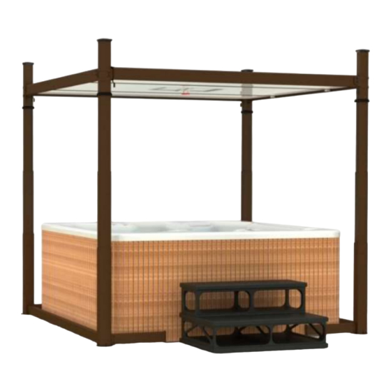
COVANA Evolution Owner's Manual
Spa cover
Hide thumbs
Also See for Evolution:
- Manual (79 pages) ,
- Installation manual (60 pages) ,
- User manual (32 pages)
Table of Contents
Advertisement
Quick Links
Advertisement
Table of Contents

Related Manuals for COVANA Evolution


Summary of Contents for COVANA Evolution
- Page 3 EVOLUTION COVER page - COVANA SPA COVER MANUFACTURER OWNER'S MANUAL MANUAL NO. 252808 252808 OWNER'S MANUAL REVISION 0...
- Page 4 EVOLUTION COVER EVOLUTION COVER MANUAL NO. 252808 First edition 2023-12-08 REVISION DESCRIPTION DATE OWNER'S MANUAL NEW RELEASE 2023-12-08 252808 OWNER'S MANUAL REVISION 0...
- Page 5 EVOLUTION COVER page- INTRODUCTION CONGRATULATIONS FOR THE PURCHASE OF YOUR NEW COVANA COVER IMPORTANT INFORMATION SAFETY DRUGS AND ALCOHOL IMPORTANT SAFETY INSTRUCTIONS RISK OF ELECTROCUTION ELECTRICAL WARNING MODIFICATIONS TO THE COVER POSITION OF THE KEY SWITCH LABELING RISK OF ELECTROCUTION...
- Page 6 WIRING DIAGRAM (EUROPE) – 50 HZ, 230 VAC OPERATOR MAINTENANCE WINTERIZING WASHING THE COVER POST GREASING CHAIN LUBRICATION PERIODIC MAINTENANCE TABLE TECHNICAL SPECIFICATIONS COVANA COVER FRONT ELEVATION PLAN FRAME DIMENSIONS AND FOOT PRINT CONCRETE SLAB LAYOUT OPTION ELECTRICAL SPECIFICATIONS TROUBLESHOOTING 252808 OWNER'S MANUAL REVISION 0...
- Page 7 EVOLUTION COVER page- 252808 OWNER'S MANUAL REVISION 0...
- Page 8 EVOLUTION COVER INTRODUCTION As part of its ongoing commitment to improve the quality, reliability, durability and safety of its products, Covana is proud to present this edition of the cover Owner's Manual. The various sections that make up this manual will provide you with the most recent information allowing you to understand the operation of the cover, its installation and its maintenance in order to obtain complete satisfaction and to ensure maximum safety and comfort for users.
-
Page 10: Drugs And Alcohol
NOTE READ AND FOLLOW ALL INSTRUCTIONS. Before reproducing or copying this manual, in whole or in part, written consent must be obtained from Covana. Covana reserves the right to make WARNING changes without notice and without incurring any obligation. CALIFORNIA PROPOSITION 65... - Page 11 Have any repairs, adjustments or mechanical Never operate the cover until all people and work performed by a certified Covana dealer as objects are out of the spa. soon as possible when you notice any malfunction.
-
Page 12: Risk Of Electrocution
EVOLUTION COVER DON'TS CAUTION Do not operate the unit before all mechanical All four jacks of the cover must be properly and electrical connections are completely anchored to the foundation using the anchoring installed. holes of the jack base plate. The optional non-... -
Page 13: Electrical Warning
No. 6 AWG (4.11 mm / 13.30mm ). (NEC art. 680). Replace electrical components with original components provided or approved by Covana. Ask your dealer for replacement parts. MODIFICATIONS TO THE COVER To reduce the risk of electrical shock, replace a damaged electrical cord immediately. - Page 14 EVOLUTION COVER POSITION OF THE KEY SWITCH WARNING The key switch must be permanently installed and located 5 ft (1.5 m) away from the spa and 5 ft (1.5 m) above the deck or ground level, see Figure Make sure the user has a clear view of the cover when operating it.
- Page 16 EVOLUTION COVER INFORMATION ON THE ELECTRICAL LABELING CABLES This section features the labels affixed to various These labels inform the user about the danger of components for your safety. electrocution with the presence of water near the electrical wiring.
- Page 17 EVOLUTION COVER page- KEY SWITCH OPERATION DIAGRAM TECHNICAL SPECIFICATION LABEL This label shows the user how to push the button These labels show the user the important technical while turning the key into the key switch to raise or specifications. They are located on the operator lower the cover.
- Page 18 EVOLUTION COVER NO STEP LABEL This label is a reminder not to step on this area of the unit. The label is located on the top of the operator cover. FIGURE 10: AVOID DROWNING LABEL DO NOT STEP ON THE COVER LABEL This label is a reminder not to step on the cover.
- Page 20 EVOLUTION COVER GLOSSARY PART IMAGE FUNCTION This all-weather seal protects sleeves from damage due Sleeve all-weather seal to weather. The contour seal makes sure there is uniform contact Contour seal between the cover panels and the spa. Contour seal installation clips are used during the...
- Page 21 EVOLUTION COVER page- PART IMAGE FUNCTION The foot bracket provides a solid footing of the cover and Foot bracket is attached to the bottom of the jack. Spa entrance U-frame This link is installed under the entrance steps of the spa.
- Page 22 EVOLUTION COVER PART IMAGE FUNCTION Jacks are a very important component of the cover. Jack They allow the cover to lift up and down. The operator powers and controls the lifting mechanism Operator of the cover. The sleeves are aluminum extrusions to hide and Sleeve protect the jacks.
- Page 23 EVOLUTION COVER page- PART IMAGE FUNCTION C-channel The C-channel is the outer frame of the cover panels. The inner corner bracket links the C-Channels. It creates Inner corner bracket the frame of the cover panels. The escape hatch is a removable panel component of Escape hatch the middle cover panel.
- Page 24 EVOLUTION COVER PART IMAGE FUNCTION The wiper bracket is attached under the I-beams. This Wiper bracket component ensures the waterproofing of the cover. I-to-C connection plate The short I-to-C connection plate is installed between (short) the I-beams and C-Channels.
-
Page 26: Installation Procedure
CAUTION foundation, a set of non- permanent mounting plates is required. The cover must be installed by a certified Covana installer. Having the cover installed by someone Four screws to fasten the key switch to its who is not certified will void the warranty. - Page 27 Damage caused by inadequate foundation MOUNTING PLATE section for more information. construction is not covered by the Covana For an existing foundation, refer to the Technical warranty. It is the responsibility of the owner to Specifications section to see the diagram.
-
Page 28: Unpacking Procedure
The unpacking procedure is in the envelope on the side of the crate. NOTE If you find any damage, refer to the Covana Damaged claim form attached to the crate, take pictures and simply refuse the delivery from the carrier. - Page 29 EVOLUTION COVER page- HARDWARE IDENTIFICATION TABLE DESCRIPTION CODE 202000/01 5/16-18 x 2" Hex bolt to assemble the lower frame (slate or mocha) 188801 1/4-20 x 2 1/4" Hex bolt to assemble the feet of the posts 202013/14 1/4-20 x 3/4" Carriage bolt to assemble the front frame cut-out (slate or mocha) 240803 No.
-
Page 30: Assembly Preparation
EVOLUTION COVER ASSEMBLY PREPARATION This section shows you how to assemble the cover panels. FIGURE 16: TOP ORIENTATION OF I-BEAM FOAM SPACER INSTALLATION 1. Assemble the two I-beam short connection NOTE plates as shown in Figure The following figures represent the assembly of 2. - Page 31 Figure 18 . Ensure the TOP/DESSUS escape hatch installed are not approved by label located in the panel hole is properly Covana and product certification will be void. oriented. FIGURE 18: PANEL INSTALLATION 2. Locate the escape hatch box. FIGURE 20: ESCAPE HATCH INSTALLATION 3.
- Page 32 EVOLUTION COVER FIGURE 23: TOP ORIENTATION OF I-BEAM CAUTION Make sure the I-beam has cleared the bottom and top sections. FIGURE 21: RECTANGULAR COVER While inserting the I- beam in the C- channel, make sure it is always square with the C-channel.
- Page 33 EVOLUTION COVER page- 8. Insert the inner corner brackets in both ends of the remaining C- channels. Use the provided Robertson sheet metal #8 x 3/4 in. screws on the inside holes, see Figure CAUTION Do not overtighten the screws to avoid thread damage.
- Page 34 EVOLUTION COVER the inside holes of the side C-channels, see Figure WARNING Do not overtighten screws as they might break. FIGURE 29: CORNER AND C-CHANNEL INSTALLATION 10. On the other end of the cover, slide the other corner bracket and C-channel assembly.
- Page 35 EVOLUTION COVER page- FIGURE 32: OPERATOR AND JACKS INSTALLATION FIGURE 33: FOOT BRACKET INSTALLATION DESCRIPTION 3. Slide the alignment vertical legs of the foot in OPERATOR the bottom alignment slots of the jack, see Figure 33 Figure MOTOR SIDE LEFT JACK...
- Page 36 EVOLUTION COVER FIGURE 36: DRIVE SHAFT INSTALLATION 9. Hold the left- hand non- motor- side jack assembly upright and in line with the left FIGURE 35: SCREW INSTALLATION drive shaft. Use a 3/4" adjustable wrench to 6. Repeat previous steps with the non- motor carefully rotate the square shaft of the jack to right-hand side foot.
- Page 37 EVOLUTION COVER page- NOTE Do not fully tighten the screws. The drive shaft may fall off during operation, and reassembling can be done faster when the screws have not been fully tightened, see Figure FIGURE 39: SPA ENTRANCE U-FRAME LINK AND METAL...
- Page 38 EVOLUTION COVER FIGURE 40: SHORT U-FRAME INSTALLATION 16. Check whether the drive shafts fell off during installation. If so, review the previous steps. If not, tighten all U-frame screws. FIGURE 41: JACK LOCK SCREW (ITEM A) DANGER DESCRIPTION Failure to verify the proper installation of the drive...
- Page 39 EVOLUTION COVER page- FIGURE 42: CLIP-ON BARREL NUT INSTALLATION FIGURE 44: MOUNTING SCREW ON THE SLEEVE DESCRIPTION 22. Install the all-weather seal on each post and CLIP-ON BARREL NUT make sure it is slid all the way down against the top of each outer sleeve, see...
- Page 40 EVOLUTION COVER C-Channels with four painted Phillips M6 x 20 mm bolts and 1/4" painted washers. Install the first screw on position A and for the remaining screws, keep following the pattern shown in Figure WARNING Make sure the sleeve is correctly pressed against the outer shell before installing the M6 x 20 mm screws.
- Page 41 EVOLUTION COVER page- FIGURE 51: RUBBER CAP INSTALLATION FIGURE 49: INSTALLATION PATTERN FOR CORNER BRACKET SCREWS ATTACHED TO THE SLEEVE CAUTION 29. Check the installation of the brackets by The four jacks will have to be anchored to the trying to lift each sleeve. Review previous...
- Page 42 EVOLUTION COVER TROUBLESHOOTING section or contact your local dealer. 6. Lower the cover and make sure it stops at the point of contact with all the foam spacers on the spa. If not, adjust the corner brackets (see corner bracket installation in the Lifting Mechanism section).
- Page 43 EVOLUTION COVER page- FIGURE 53: FASTEN THE BACKPLATE WITH FOUR SCREWS FIGURE 54: LOCATION OF THE PLATES NON-PERMANENT MOUNTING PLATES If you don’t have non-permanent mounting plates, skip this section. NOTE This setup is only available for spa base sizes larger than 82"...
- Page 44 EVOLUTION COVER positioned over the U- frames, you may continue with the wiper installation. WIPER INSTALLATION 1. Lift the cover halfway up to proceed to the next steps. The next steps are important to minimize water intrusion. CAUTION There are four wipers.
-
Page 45: Seal Installation
EVOLUTION COVER page- SEAL INSTALLATION WARNING The recommended tool to install the seal properly is a J-Roller with rubber roller (Covana part no. 239693), see Figure The roller is not included in the tools. It must be free of scratches, clean and non-abrasive. - Page 46 EVOLUTION COVER FIGURE 62: SEAL JOINT CONNECTOR 7. Start installing the seal joint with the FIGURE 61: MASKING TAPE AND CLIPS adhesive layer facing up towards the cover, Figure 62 Figure CAUTION CAUTION The use of masking tape is recommended since it will protect the spa acrylic from the clip glue.
- Page 47 EVOLUTION COVER page- to slowly and fully release from the seal clips. WARNING You can also use a non-abrasive plastic tool or your fingers to help release the seal from At this point, if there is no water in the spa and the the clips.
-
Page 48: Electrical Connections
Covana. CAUTION Replace electrical components with original All electrical work should be done by a certified components provided or approved by Covana. electrician, otherwise certification Ask your dealer for replacement parts. - Page 49 EVOLUTION COVER page- ELECTRICAL WARNING WARNING For AC-operated model: To reduce the risk of electrical shocks, the green- colored terminal (or the terminal marked “g,” “gr,” “ground,” “grounding” or with a symbol) that is located inside the supply terminal box or compartment...
- Page 50 EVOLUTION COVER GROUNDING AND POWER SUPPLY CONNECTIONS 1. Remove the screws (4) on the bottom side of the operator cover and remove the cover, see Figure 2. For the complete wiring diagrams refer to the Electrical diagrams section (North American models and European models).
- Page 51 EVOLUTION COVER page- LIMIT SWITCH ADJUSTMENT Figure 68) out from the operator frame. Be careful not to rotate the cam wheels (items C and D, Figure 68). WARNING Disconnect or turn off the power supply before starting any work on the cover. All electrical work should be performed by a qualified electrician.
- Page 52 EVOLUTION COVER FIGURE 69: CAM WHEELS 5. Once the up limit is set to the desired position, reinstall the cam plate to its original location and make sure that it is properly inserted in the slot of each cam. Never operate the system without the cam plate and retaining screw installed.
- Page 53 EVOLUTION COVER page- INSTALLATION CHECKLIST (CUSTOMER COPY) To ensure proper installation you must carefully read this checklist and confirm that you have completed all steps of the installation. The customer must receive a completed copy of this checklist. (Please check each circle when the point is completed) The base preparation steps are done correctly.
- Page 55 EVOLUTION COVER page - INSTALLATION CHECKLIST (INSTALLER COPY) To ensure proper installation you must carefully read this checklist and confirm that you have completed all steps of the installation. The customer must receive a completed copy of this checklist. (Please check each circle when the point is completed) The base preparation steps are done correctly.
- Page 56 EVOLUTION COVER 252808 OWNER'S MANUAL REVISION 0...
- Page 58 EVOLUTION COVER OPERATE THE COVER Read the SAFETY section of this manual carefully before operating the cover. RAISING/LOWERING THE COVER WITH THE KEY SWITCH 1. Make sure all debris and snow are removed from the top of the cover before operating.
- Page 59 EVOLUTION COVER page- MANUAL OPERATION OF THE COVER WARNING Disconnect or turn off and secure all power supplies before starting any intervention on the cover. 1. Disconnect or turn off and secure the power supply. 2. Remove the four screws at the bottom of the...
-
Page 60: Using The Escape Hatch
Figure slots located in the center part of the handle, Figure FIGURE 74: ALIGN THE SLOTS 3. Insert the COVANA key or ANY key into one of the slots, see Figure FIGURE 72: INTERIOR HANDLE 2. Push straight up on the escape hatch and... -
Page 62: Electrical Diagrams
EVOLUTION COVER ELECTRICAL DIAGRAMS Next pages of this section show electrical diagrams of the cover. 252808 OWNER'S MANUAL REVISION 0... - Page 63 EVOLUTION COVER page- WIRING DIAGRAM (NORTH AMERICA) – 60 HZ, 120 VAC OPERATOR 252808 OWNER'S MANUAL REVISION 0...
- Page 64 EVOLUTION COVER 252808 OWNER'S MANUAL REVISION 0...
- Page 65 EVOLUTION COVER page- WIRING DIAGRAM (EUROPE) – 50 HZ, 230 VAC OPERATOR 252808 OWNER'S MANUAL REVISION 0...
- Page 66 EVOLUTION COVER 252808 OWNER'S MANUAL REVISION 0...
-
Page 68: Maintenance
WARNING Using any type of fabric or plastic canvas to cover The product lifetime depends on the time you spend the Covana cover during hot weather may for the care and maintenance of the cover. damage the components. Only use such... - Page 69 EVOLUTION COVER page- 3. Quickly rinse very thoroughly to remove all traces of soap; otherwise, a film will build up giving the cover a dull, dirty appearance. WARNING Never use a pressure washer or high pressure to clean the cover. The high pressure could puncture the fiberglass panels.
- Page 70 6. Raise the jacks until they reach the 8. Inspect the chains for signs of deterioration. maximum height, see Figure If this is the case, call your local Covana dealer, see Figure FIGURE 81: JACK CHAINS FIGURE 79: JACKS RAISING 9.
-
Page 71: Chain Lubrication
EVOLUTION COVER page- CHAIN LUBRICATION This procedure shows how to lubricate the transmission power chain attached to the operator. “Mobil Epic MOLY Grease” recommended for cold and hot climates. Ideally, a sprayable grease or an equivalent low temperature synthetic grease. -
Page 72: Periodic Maintenance Table
Remove the escape hatch and clean it with a mild detergent (i.e., dishwashing detergent) and water. Rinse well using only water. *Contact your local Covana dealer Please call your Covana dealer for any mechanical, electrical or aesthetic maintenance. 252808 OWNER'S MANUAL REVISION 0... -
Page 75: Technical Specifications
EVOLUTION COVER page - TECHNICAL SPECIFICATIONS COVANA COVER FRONT ELEVATION PLAN 252808 OWNER'S MANUAL REVISION 0... -
Page 76: Frame Dimensions And Foot Print
EVOLUTION COVER FRAME DIMENSIONS AND FOOT PRINT 252808 OWNER'S MANUAL REVISION 0... - Page 77 EVOLUTION COVER page- COVER 8 FT 9 FT 10 FT 11 FT LENGTH 118'' 130.5'' 142.5'' 154.5'' (299.7cm) (331.5cm) (362cm) (392.4cm) 105.75'' 118.25'' 130.25'' 142.25'' (268.5cm) (300.4cm) (330.8cm) (361.3cm) 98'' 110.5'' 122.5'' 134.5'' (249cm) (280.7cm) (311.2cm) (341.6cm) 106'' (269.2cm) 100.5'' (255.2cm)
- Page 78 EVOLUTION COVER CONCRETE SLAB LAYOUT OPTION 252808 OWNER'S MANUAL REVISION 0...
- Page 79 EVOLUTION COVER page- COVER 8 FT 9 FT 10 FT 11 FT LENGTH 118'' 130.5'' 142.5'' 154.5'' (299.7cm) (331.5cm) (362cm) (392.4cm) 105.75'' 118.25'' 130.25'' 142.25'' (268.5cm) (300.4cm) (330.8cm) (361.3cm) 98'' 110.5'' 122.5'' 134.5'' (249cm) (280.7cm) (311.2cm) (341.6cm) 106'' (269.2cm) 100.5'' (255.2cm)
- Page 80 10 A single-pole GFCI (not included) Current draw Max 6 A WARNING Covana does not allow any modifications of the electrical system. Covana reserves the right to void the warranty if any modifications is done without its approval. OPERATION LIMITATIONS WARNING The cover should never be used if the following conditions are reached.
-
Page 82: Troubleshooting
The debris on the cover is too (See Foundation Preparation section). heavy. If all previous attempts failed, contact your local authorized Covana dealer. Lower the cover completely and fasten the post back in at the correct height. The post screws (attached to the outer shell) are loose. - Page 83 If all previous attempts failed, contact your local authorized Covana dealer. The chain is broken. Call your local certified Covana dealer for A spring pin is broken. The cover raises technical support. unevenly. A drive shaft has fallen off.
- Page 84 EVOLUTION COVER PROBLEM PROBABLE CAUSES SOLUTIONS Remove power before performing electrical work. Ask a certified electrician only. Open the The cam plate is incorrectly operator and check for faulty up and down positioned or missing. limit switches. Cover lowers but The key switch is faulty.
Need help?
Do you have a question about the Evolution and is the answer not in the manual?
Questions and answers