
Related Manuals for WEG WEMOB-STATION-CCS-30kW Series


Summary of Contents for WEG WEMOB-STATION-CCS-30kW Series
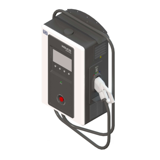
- Page 1 Motors | Automation | Energy | Transmission & Distribution | Coatings Installation and Operation Manual WEMOB-STATION-CCS-30kW WEMOB-STATION | 1...
- Page 2 Installation and Operation Manual Series: WEMOB-STATION-CCS-30kW Language: English Document: 10010893176 / 01 Model: STATION CCS-2 30 kW Publication Date: 06/2023 2 | WEMOB-STATION...
-
Page 3: Table Of Contents
Table of Contents Table of Contents 1 SAFETY INSTRUCTIONS ......................... 5 1.1 SAFETY WARNINGS IN THE MANUAL ..................... 5 1.2 PRELIMINARY RECOMMENDATIONS ..................... 5 1.3 CARE WITH THE CHARGING CABLE ....................6 GENERAL INFORMATION ........................7 2.1 ABOUT THE MANUAL ........................7 2.2 TERMS AND DEFINITIONS USED IN THE MANUAL: .............. - Page 4 Table of Contents 6.6 FACTORY RESET ..........................37 6.7 FIRMWARE UPDATE ........................38 6.8 CONNECTIVITY INDICATION ......................39 7 OPERATION ............................40 7.1 "ALWAYS AUTHORIZED" OPERATING MODE ................40 7.2 "AUTHORIZED BY LOCAL LIST OR OCPP SERVER" OPERATING MODE ......... 44 7.3 CHARGING DETAILS ........................
-
Page 5: Safety Instructions
Safety instructions 1 SAFETY INSTRUCTIONS This manual contains the necessary information for the correct installation and operation of the WEMOB- STATION electric vehicle charging station. It was prepared to be used by people with proper technical training or qualifications to operate this kind of equipment. -
Page 6: Care With The Charging Cable
NOTE! Read this manual thoroughly before installing or operating this equipment. WEMOB® is a trademark of WEG S/A. 1.3 CARE WITH THE CHARGING CABLE Follow the instructions below to avoid damage to the charging cable: Unwind the entire charging cable before starting to use it;... -
Page 7: General Information
This manual contains directions for installing and commissioning the WEMOB-STATION EV charging station and describes its main features. Copying the content of this manual, in whole or in part, is prohibited without WEG’s written consent. 2.2 TERMS AND DEFINITIONS USED IN THE MANUAL: A: Ampere, electric current level unit of measurement. -
Page 8: About The Charging Station
General Information 2.3 ABOUT THE CHARGING STATION The WEMOB-STATION electric vehicle charging station is a high-performance product that provides fast charging of electric vehicles at alternating current (AC) or direct current (DC), individually or simultaneously, controlling, monitoring and protecting the equipment and users. It has one (1) standard CCS (Combined Charging System) type 2 direct current (DC) combo connector. -
Page 9: Identification Label
The WEMOB-STATION charging stations are made with steel sheets painted and processed (cut, drilled, bent, chemically treated, painted and finished) by WEG or accredited manufacturers, ensuring quality in every step of the manufacturing process. The unpainted parts of the station are galvanized or otherwise treated to ensure corrosion resistance. -
Page 10: Connectors
General Information 2.7 CONNECTORS The WEMOB-STATION has a 4.3 m charging cable with CCS-2 Combo plug, suitable for the maximum output current of the charging station (80 A), which can fit a variety of electric vehicles (EV): Figure 3: WEMOB-STATION CCS-2 connector model To release the connector from the socket located on the side of the station, perform the sequence of movements shown below. -
Page 11: Led Indicator And Audible Alarms
General Information 2.8 LED INDICATOR AND AUDIBLE ALARMS Over the socket for keeping the charging plug is a set of LED indicators that provide visual information about the operating status of the charging station. It consists of four (04) LEDs, which can light up or flash together or individually, in various colors. -
Page 12: Receiving And Storage
General Information 2.9 RECEIVING AND STORAGE The WEMOB-STATION is supplied in an OSB wood box. Upon receipt, check that: The identification label matches the purchased model; Damages occurred during transportation. If any problem is found, contact the carrier immediately;... -
Page 13: Installing And Connecting
Installing and Connecting 3 INSTALLING AND CONNECTING This chapter describes the mechanical and electrical installation procedures for the WEMOB-STATION. The directions and suggestions must be observed in order to ensure the safety of people and equipment and its proper operation. 3.1 RECOMMENDED HANDLING PROCEDURE It is recommended to completely remove the packaging only after positioning the WEMOB-STATION charging station in the final place of operation. -
Page 14: Mechanical Installation
Installing and Connecting ATTENTION! Use personal protective equipment (PPE). If any component has problems (damage), it is recommended: Stop opening the package immediately; Contact the carrier and formally record the problem encountered; Photograph the damaged parts and/or components. 3.2 MECHANICAL INSTALLATION The WEMOB-STATION is designed for indoor or outdoor operation. -
Page 15: Cleaning And Maintenance
Install the station in environments with air circulation; Maximum altitude: 2000 m above sea level - rated conditions. For applications at higher altitudes, contact WEG; Condensation must not cause conductivity in the pollution. 3.2.2 Cleaning and Maintenance... - Page 16 Installing and Connecting Charging cable and connector: check the connector and cable for cracks, check if the cable jacket is in perfect condition and that no internal wires of the cable are visible; Condition of the conductors and theirs connections, especially the protective ones; ...
- Page 17 Installing and Connecting LOOSEN UP THE 4 M6 CROSS- LOOSEN UP THE 4 M4 CROSS- CLEFT SCREWS (PHILIPS). MOUNTED SHUTTER. CLEFT SCREWS, CLEAN OR OBS: THE SCREWS ARE REPLACE THE FILTERS. UNMISSABLE, THEY ARE FIX THE FILTERS USING THE 4 M4 ATTACHED TO THE SET OF SCREWS.
-
Page 18: Corrective Maintenance
That must be done especially when the protection devices actuate without any known reason. When the protection circuit breaker trips, identify and solve the cause before turning the equipment back If the WEMOB-STATION is defective, contact WEG Technical Support on the phone 0800-7010701 or e- mail 0800@weg.net. -
Page 19: Mounting
Pole mounting: to fix the WEMOB-STATION on a pole, it is necessary to purchase the pole kit informing WEG material 16084832. The kit, in addition to the pole, contains screws and anchor bolts to fix the pole and the charging station. - Page 20 Installing and Connecting The pole must be fixed using the four (4) anchor bolts provided with the pole kit, as shown in the following figures: ANCHOR BOLT 3/8”x3.3/4” Figure 11: Pole anchor bolt detail in inches and mm - [ “ ] mm Figure 12: Pole base detail in inches and mm - [ “...
- Page 21 Installing and Connecting M10 FIXING KIT - STAINLESS TOTEM COVER ANCHOR BOLT BASE ILLUSTRATIVE Figure 13: Pole mounting detail ATTENTION! It is essential to ensure the correct installation of the WEMOB-STATION, thus avoiding possible damage to the charging station and operators. WEMOB-STATION | 21...
-
Page 22: Electrical Installation
Installing and Connecting 3.3 ELECTRICAL INSTALLATION The following information is a guide to the proper installation. Also comply with the applicable local regulations for electrical installations. DANGER! The WEMOB-STATION demands high current and consequently high power for its operation. Make sure that the demand requirements will be met by the electrical infrastructure of the facilities;... -
Page 23: Protection Device
Installing and Connecting PE R POWER INPUT Figure 14: Power input 3.3.3 Protection Device ATTENTION! The WEMOB-STATION must be connected to an exclusive four-pole protection circuit breaker for the charging station power circuit with residual current protection 30 mA sensitivity (AC) type Determine the rated operating current of the circuit breaker upstream from the WEMOB-STATION charging station according to the data provided by the manufacturer, the maximum input current of the station, the short circuit levels of the installation and the station, the gauge and length of the power cables. -
Page 24: One-Line Diagram
Installing and Connecting 4 ONE-LINE DIAGRAM Figure 15: One-line diagram Table 4: Characteristics of the one-line diagram components Station Model (Station Description Power) (Component Tag) 30 kW Molded-case circuit breaker (Q1) 80 A NH2 aR fuse (1F1/1F2) 100 A Circuit breaker (Q2) 10 A 24 | WEMOB-STATION... -
Page 25: Emergency Pushbutton
Emergency 5 EMERGENCY PUSHBUTTON The WEMOB-STATION charging station has an emergency pushbutton on the front. In emergency situations the button must be pressed! When pressed, the charging in progress will be immediately interrupted, and the power output safely de-energized, protecting the user and the station itself. The display will remain on to report the fault and show instructions to the user. -
Page 26: Connectivity
The charging station is commissioned through web pages implemented in the station firmware. To that end, the station generates an "access point", which is a Wi-Fi network named WEG-EVSE-xxx, so that another device (smartphone, tablet, computer, notebook etc.) can access the station settings. - Page 27 The representation of these icons varies depending on the Windows® version installed. The all available wireless networks in your area will be displayed. Click on the network identified by the SSID (identification name) as WEG-EVSE-xxx and then click on "Connect". In the next window, enter the password "password";...
- Page 28 Connectivity Figure 19: Station configuration page via web browser 4. Fill in the following fields: Wi-Fi: Enables or disables the Wi-Fi network interface. Ethernet: Enable: enables or disables the wired Ethernet network interface (RJ45). 28 | WEMOB-STATION...
- Page 29 Can be used: _ (underscore) and - (hyphen); There is a distinction between uppercase and lowercase letters. OCPP Server URL: Text field for WEG or third party OCPP server address. Example for WEG Server: ws://ocpp.weg.net/ocpp/chargebox WEMOB-STATION | 29...
- Page 30 Connectivity Charging Authorization: it defines whether the charging station requires authentication to start charging. Three (3) authorization modes are available: Always Authorized: Allows charging without authentication. Select it to allow free access to charges; Authorized by Local List: The users are identified (authenticated) through RFID cards registered in the “Local List”.
- Page 31 Connectivity the IP address of the network. "DHCP": the station obtains an IP address automatically, "Static": IP address manually assigned by the user. These fields must be filled in as presented in the previous item "Ethernet"; To finish, click on "Connect". If the connection is successful, a message will be displayed saying "Setup is complete".
-
Page 32: Wi-Fi Network
If it is the first configuration of the station on the Wi-Fi network, the station generates an "access point", a Wi-Fi network identified as WEG-EVSE-xxx, so that another device (smartphone, tablet, computer etc.) can access the station Wi-Fi network settings. -
Page 33: Cellular
Connectivity RJ45 CONNECTOR Figure 22: Location of the RJ45 connector on the electronic control board 6.4 CELLULAR The charging station needs to be installed in a location with a strong cellular signal. You can check the signal strength using a cell. Check if you have full bars on the device. The higher the level, the better the cellular network signal. - Page 34 Connectivity Figure 23: Location of the SIM card slot on the electronic control board 3. Align the SIM Card with the slot on the electronic control board. For the correct insertion, the beveled edge of the SIM card must be aligned to the right and the metal contacts face downwards. See the drawing guiding the SIM card assembly in the slot;...
-
Page 35: Rfid
Connectivity Figure 25: Procedure to remove the SIM card 6.5 RFID The factory setting of the WEMOB-STATION charging station does not require authentication, with free access for charging in the "Always Authorized" operating mode. To require authentication, this setting must be changed according to Section 6.1 COMMISSIONING on page 26. - Page 36 Connectivity (1) flashing green LED 1x beep (2) solid green LED Figure 26: Registration of the RFID "Master" Card NOTE! Only one "Master" card can be registered; The "Master" card cannot be used to complete a charging procedure; ...
-
Page 37: Factory Reset
Connectivity To exclude a "User" card from the Local List, the procedure is the same as for inclusion—just repeat the previous steps. If the card is already registered in the Local List, it will be deleted. If the exclusion is successful, the station will emit 2 (two) short beeps, and the RFID reader LED will change to solid green. -
Page 38: Firmware Update
It is only possible to download the latest firmware version and not to go back to an old version. Files are available at: http://updates.weg.net/chargingstation ATTENTION! Point at the firmware directory (URI) corresponding to the purchased charging station model, at the risk of damaging the charging station. -
Page 39: Connectivity Indication
Connectivity 6.8 CONNECTIVITY INDICATION On the upper right corner of the WEMOB-STATION display, an icon of the network connection is shown. The icon indicates the signal strength (Wi-Fi and cellular networks), if the station is commissioned, if it is connected to an OCPP server etc. ... -
Page 40: Operation
Operation 7 OPERATION After completing the mechanical and electrical installation, the WEMOB-STATION is ready to start operating by setting the “Q1” circuit breaker. When the charging station is energized, the display shows an opening video, and the status LEDs of the connectors will light solid GREEN, indicating that the station is ready to start charging. - Page 41 Operation Hello, select an option Connector Connector 2 Connector 3 CHAdeMO Type 2 Type 2 CCS 43 kW 150 kW 150 kW More options Available Available Available Figure 29: Home screen (example 150 kW) 2. Remove the plug from the charging station and plug it into the electric vehicle; Connector 2 –...
- Page 42 Operation Connector 2 – CCS – Type 2 – Max. 150 kw Connecting... Cancel Figure 31: Screen indicating that the electric vehicle has been connected and is in the process of being recognized It is possible to cancel the process by pressing the "Cancel" button. 4.
- Page 43 Operation The station LED will be YELLOW, indicating that the charge is complete, and the user intervention is required. The home screen and charging details screen show the message "Completed" next to the selected connector. User intervention: in this case, the charging process can be ended at any time through the "Stop" button on the screen with details of the charging in progress, or it must be ended through the vehicle.
-
Page 44: Authorized By Local List Or Ocpp Server" Operating Mode
Operation 7.2 "AUTHORIZED BY LOCAL LIST OR OCPP SERVER" OPERATING MODE Connector 2 – CCS – Type 2 – Max. 150 kw Choose how to release With the app With your card Start the use with the app or Approximate your card until system you have access to you hear the bipe and the AVAILABLE led flashes... - Page 45 Operation Connector 2 – CCS – Type 2 – Max. 150 kw Authentication Approximate your card of ((RFID)) Wait until you hear the bipe and the AVAILABLE led flashes Return 60 s... Figure 36: Screen with instructions for releasing the charging via RFID If the card is not recognized, a new screen will be displayed for the user to try again or informing that the card was declined.
- Page 46 Operation Connector 2 – CCS – Type 2 – Max. 150 kw Authentication Your card has been declined Contact the person in charge of the charging station or service Return 60 s... Figure 38: Screen indicating a problem in the RFID card authentication NOTE! The station will emit a long beep when an unregistered card approaches the RFID reader.
- Page 47 Operation 4. After the connection to the vehicle, the station begins a communication and safety testing process. The charging station will indicate it in solid YELLOW. If 60 seconds (60 s) elapsed and the connection between the station and the vehicle is not established, the station will emit a long beep and return to the "available"...
- Page 48 Operation Complete charge: after the electric vehicle battery is fully charged, the charging station will keep the connector locked until the vehicle stops the charging process. The station LED will be YELLOW, indicating that the charge is complete, and the user intervention is required.
-
Page 49: Charging Details
Operation After disconnecting the charging cable from the electric vehicle, the station will return to the start status, with solid GREEN indication. The connector will be available for the next charging process. NOTE! When the electric vehicle is completely charged, insert the plug into the socket located on the side of the station. -
Page 50: Fully Charged
Operation 7.3.2 Fully Charged Connector 2 – CCS – Type 2 – Max. 150 kw Recharge Finished Remove the connector Release the spot for the next one Charging summary Energy Charging time 70 kWh 00:10:00 Go to start Menu 60 s... Figure 45: Screen with details of a completed charge 1 - Displays data of the completed charge on the selected connector. -
Page 51: Error When Charging
Operation 7.3.3 Error When Charging Connector 2 – CCS – Type 2 – Max. 150 kw Charging error Remove the connector and release the spot or try again Charging summary Charging time Energy 00:10:00 70 kWh Connect another See error vehicle 60 s... -
Page 52: Errors
Operation Hello, select an option Connector 3 Connector 1 Connector 2 Type 2 CHAdeMO Type 2 CCS 150 kW 150 kW 43 kW More options Stopped Completed Available Figure 47: Home screen showing the status of each connector Table 5: Connector status indication Description Available Connector available, ready to use... - Page 53 Operation Errors Page 1 of 1 CODE DATE AND TIME DESCRIPTION Emergency pushbotton pressed Active Overtemperature Solved Removal of the WIFI file Solved Overcurrent detection Solved CCS Cable Overtemperature Solved Insulation fault detected Solved Return Most recent Oldest 60s... Figure 48: Error details screen Errors are classified according to the level of action: ...
-
Page 54: Technical Data
Technical Data 8 TECHNICAL DATA Table 7: Technical data Input Data Rated voltage 380 - 415 VAC ± 10 % 3F+N+PE Rated frequency 50/60 Hz ± 5 % Maximum input current 58 A 0.9 from 25 to 50% load Power factor 0,98 from 50 to 100% load CCS Output Data Output voltage... -
Page 55: Wemob-Station Dimensions
Technical Data 8.1 WEMOB-STATION DIMENSIONS Figure 49: WEMOB-STATION dimensions in inches and mm - [ “ ] mm WEMOB-STATION | 55... -
Page 56: Anatel
Anatel 9 ANATEL “This device has no right to protection against harmful interference and cannot cause interference in duly authorized systems.” "It incorporates product approved by ANATEL under number 17035-20-03402". “This device has no right to protection against harmful interference and cannot cause interference in duly authorized systems.”... -
Page 57: Lgpl General Information
LGPL license, their use being subject to compliance with copyright. more details, read Lesser General Public License, accessible http://licencas.softwarelivre.org/lgpl-3.0.pt-br.html WEG does not provide technical support for these codes and will keep them available for the period provided for in the LGPL. WEMOB-STATION | 57...
Need help?
Do you have a question about the WEMOB-STATION-CCS-30kW Series and is the answer not in the manual?
Questions and answers