
Related Manuals for WEG RTDW


Summary of Contents for WEG RTDW
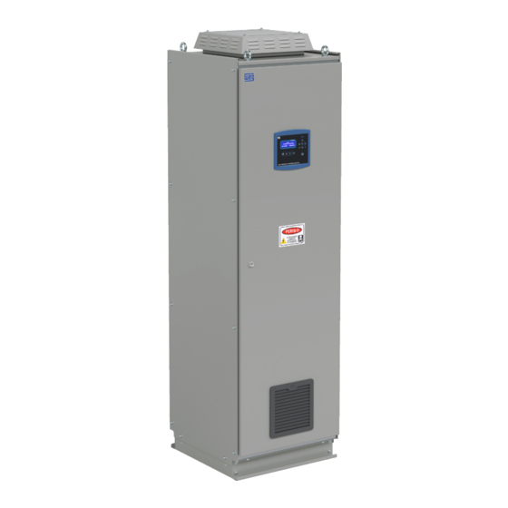
- Page 1 Motors I Automation I Energy I Transmission & Distribution I Coatings RTDW Digital Three-Phase Rectifier | Battery Charger User’s Manual...
- Page 2 User’s Manual Series: Digital Three-Phase Rectifier | Battery Charger Language: English Document: 10008805781 / 01 Model: RTDW Publication Date: 08/2023...
- Page 3 Summary of Reviews The information below describes the revisions made to this manual. Version Review Description First edition Layout update...
-
Page 4: Table Of Contents
Summary of Reviews 1 SAFETY INSTRUCTIONS ..............1-1 1.1 SAFETY WARNINGS IN THE MANUAL ..........1-1 1.2 SAFETY WARNINGS ON THE PRODUCT ..........1-1 1.3 PRELIMINARY RECOMMENDATIONS ..........1-2 2 GENERAL INFORMATION ..............2-1 2.1 ABOUT THE MANUAL ................2-1 2.2 TERMS AND DEFINITIONS USED IN THE MANUAL ...... - Page 5 6.2.1 Date and Time Settings ..............6-2 6.2.2 Alarm and Dry Contact Output Settings ........6-2 6.3 RTDW´S OPERATION ................6-4 6.3.1 Turning the System On and Off Via the Commands Menu ..6-5 6.3.2 System Turning On Via On Switch ..........6-5 6.3.3 Turning the Rectifier On and Off ..........
- Page 6 6.7.1 Setting the Communication Parameters ........6-25 6.7.2 Termination Resistors ..............6-25 6.7.3 Reading and Writing Parameters ..........6-25 6.7.3.1 Information on the RTDW Model ........6-26 6.7.3.2 AC Input Voltage Measurements ........6-26 6.7.3.3 DC Voltage Measurements ..........6-26 6.7.3.4 Electronics Supply Voltage Measurements ....
- Page 7 Summary of Reviews 8 PREVENTIVE MAINTENANCE ............8-1 8.1 RESET TO FACTORY DEFAULT PARAMETERS........8-1 8.2 PROCEDURE TO ENTER THE MAINTENANCE MODE (MANUAL BYPASS) ..................8-2 8.3 PROCEDURE TO EXIT THE MAINTENANCE MODE (MANUAL BYPASS) ..................8-2 8.4 BATTERY MAINTENANCE ..............8-3...
-
Page 8: Safety Instructions
The following symbols are attached to the product as safety warnings: High voltages are present. Components sensitive to electrostatic discharges. Do not touch. Mandatory connection to the protective ground (PE). Connection of the shield to the ground. RTDW | 1-1... -
Page 9: Preliminary Recommendations
All repairs and maintenance jobs must be performed with the equipment completely de-energized and only by technicians of the WEG Authorized Technical Assistants. DANGER! Always disconnect all power sources (main and battery) before touching any electrical parts connected to the equipment. - Page 10 In case the supplier does accept them, contact the battery manufacturer or distributor, as they are responsible for the collection. The batteries replaced by WEG Authorized Service Centers are collected by WEG and sent to the respective suppliers for proper recycling.
-
Page 11: General Information
HMI: human-machine Interface; device that allows controlling, viewing and changing the Rectifier „ parameters. The HMI of the RTDW has control keys, navigation keys and a graphic LCD display. Heatsink: metal part designed to dissipate the heat generated by power semiconductors. - Page 12 Switching Frequency: switching frequency of the IGBTs, usually given in kHz. „ s: second. „ THD: total harmonic distortion. „ USB: universal serial bus. „ V: volts. „ VA: volt-ampere; apparent power. „ W: watt; active power. „ Ω: ohm; resistance or impedance. „ 2-2 | RTDW...
-
Page 13: Product Description
3.2 GENERAL CHARACTERISTICS 3.2.1 Output Types The RTDW can operate with three types of output converters: DCU, DDU or Direct. By default, the system used is the DCU, allows a more precise and effective control of the consumer voltage. 3.2.1.1 DCU Converter (Default Configuration) The DCU system is based on the use of a DC/DC converter to regulate the output voltage. - Page 14 Note: This circuit is disabled in RTDW models that have positive or negative terminals grounded. The RTDW has electronics with dual power supply and a supervisory system that operate redundantly, providing even greater protection to the consumer's power supply in case of failure.
-
Page 15: Output Parallelism
If it is desirable to determine how each rectifier will operate: taking full load or remaining in standby, it is possible to adjust the output voltage of the individual DCU in each RTDW. To do that, it is necessary to maintain a voltage difference greater than three volts in relation to the other rectifiers in parallel. -
Page 16: Label Data
Product Description 3.3 LABEL DATA The RTDW identification label is located inside the product door. The identification label follows the model shown in Figure 3.4 on page 3-4. Rated input voltage Rated frequency WEG material Rated output voltage Output current... -
Page 17: Connecting The Module
Spare AC power supply voltage sample - Phase T Grounding (Electronics) Grounding (Earth Leakage) Main AC power supply voltage sample - Phase R Main AC power supply voltage sample - Phase S Main AC power supply voltage sample - Phase T RTDW | 3-5... - Page 18 Dry contact output 2 - NC Dry contact output 2 - C Dry contact output 2 - NO Dry contact output 3 - C Dry contact output 3 - NO Supervisory - feedback output - C Supervisory - feedback output - NO 3-6 | RTDW...
- Page 19 NTC- ambient temperature measurement signal Analog GND Power Supply - Electronics Analog 12 V Power Supply - Electronics Digital GND Power Supply - Electronics Digital 12 V Power Supply - Electronics Drives GND Power Supply Drives 24 V Power Supply RTDW | 3-7...
- Page 20 Signals for command and communication with the DCU module DB9 RELÉ Signals for command and communication with the Relays module DB25 RET1 Signals for command and communication with the Rectifier 1 module DB25 RET2 Signals for command and communication with the Rectifier 2 module 3-8 | RTDW...
-
Page 21: Relay Module (A5)
Table 3.2: Relay module signals Connector Pin Description Command and communication signals Expansion connection Relay 1 Common Relay 2 Common Relay 3 Common Relay 4 Common Relay 5 Common Relay 6 Common XC10 Relay 7 Common XC11 Relay 8 Common RTDW | 3-9... -
Page 22: Rectifier Module (A1)
AC Input - Phase R Bar S AC Input - Phase S Bar T AC Input - Phase T Bar S.R. Rectifier output (Positive) Bar N Negative +BAT E DC Link Input +BAT S DC Link Output to Battery 3-10 | RTDW... - Page 23 Product Description Figure 3.7: Identification of rectifier module connections RTDW | 3-11...
-
Page 24: Lc Filter Module (A2)
Table 3.4: Table of the LC and C Filter module signal Connector Description Bar F.LC LC filter input Bar E.IND C filter input Bar P.C. DC Link pre-charge input Bar N Negative Bar DCU/+BAT DC Link Output 3-12 | RTDW... -
Page 25: Dcu Module (A3)
Table 3.5 on page 3-14 shows the signal information for the DCU module connections, and Figure 3.9 on page 3-13 shows the position of each connector on the front of the module. Figure 3.9: Identification of the DCU module connections RTDW | 3-13... -
Page 26: Hmi Module
Digital GND Power Supply - Electronics DC-Start button signal/command DC-Start button signal/command NOTE! The connections and signal tables described above are directly applicable to the standard modules. For special modules, applied to special products, please refer to the design. 3-14 | RTDW... -
Page 27: Receiving And Storing The Product
The place must not present water infiltration or dripping. „ Good ventilation. „ The panel must be kept on the wooden base (pallet). „ The packages must not be removed. „ Vermin must not be present. „ The air relative humidity must be low. „ RTDW | 4-1... -
Page 28: Installing And Connecting
Installing and Connecting 5 INSTALLING AND CONNECTING This chapter describes the procedures for the electric and mechanical installation of the RTDW. The directions and suggestions must be observed in order to ensure the safety of people and equipment and the proper operation of the rectifier. -
Page 29: Power Connections
External RS485 communication is provided at the terminals according to the design diagram. Note the correct connection of the signals. 5.3.4 Connecting the USB Communication In addition to RS485 communication, USB communication is also provided. Check the location of the USB connector in the design. 5-2 | RTDW... -
Page 30: Dry Contact Outputs And Expansion Of Dry Contact Outputs
Installing and Connecting 5.3.5 Dry Contact Outputs and Expansion of Dry Contact Outputs The default configuration of the RTDW rectifier has eight dry contact outputs, which can be expanded to sixteen outputs. Those outputs are set as indicated in Section 6.2.2 Alarm and Dry Contact Output Settings on page 6-2. -
Page 31: Operation
Figure 6.1 on page 6-1. Table 6.1: Minimum voltage of the battery bank to perform the DC-Start Model RTDW Minimum Battery Bank Voltage 110 V 77 Vdc 125 V 86 Vdc Figure 6.1: Product electronics startup bar RTDW | 6-1... -
Page 32: First Settings
The user can also configure 50 additional alarms according to the events presented in Table 6.2 on page 6-3. As default, the RTDW has 8 dry contact outputs, expandable to 16 (on request). The outputs are activated according to the events configured in Table 6.2 on page 6-3. - Page 33 Fan 3 Fault - DCU Not applicable AVG Overtemperature - Panel AVG Overtemperature - DCU Relay 7 Relay 8 applicable XC10 XC11 AVG Overtemperature - Rectifier AVG Overtemperature - Battery Relay 8 Bypass via supervisory system Not applicable XC11 RTDW | 6-3...
-
Page 34: Rtdw´s Operation
Operation Alarms and relays can be set via WPS software (WEG Programming Suite), available at www.weg.net. To set an alarm, select the "Alarms" tab. Then follow the steps below: Click on (1) "Select Alarm" and define an available alarm number to set. -
Page 35: Turning The System On And Off Via The Commands Menu
"up" keys and press the "Enter" key in the "YES" option. To turn off the consumer, follow the steps mentioned above, select the "OFF" option and confirm the command. The product synoptic panel starts operating according to the status described Table 6.9 on page 6-14. RTDW | 6-5... -
Page 36: Turning The Bypass On And Off
"AUTOMATIC" (factory default): The equipment will keep the battery bank in floating mode, „ and, whenever a relevant discharge of the batteries is detected, a charging cycle will be performed right after the normalization of the situation that caused the battery bank to discharge. 6-6 | RTDW... - Page 37 Settings such as recharging current, voltages and time in each mode can be set via WPS. It is recommended to set these parameters according to the manual of the battery used. Figure 6.7: Command menu - DCU Mode and DDU/Direct Output Mode Figure 6.8: Menu for choosing the operation Figure 6.9: Operation confirmation menu RTDW | 6-7...
- Page 38 Operation The RTDW has a dedicated temperature sensor that must be installed at the battery bank. This sensor signals to the system control the proper levels of thermal compensation to be applied to the float voltage of the battery bank, according to the design/manufactures’ parameters, configurable via Modbus and that can be viewed in Table 6.3 on page...
-
Page 39: Lvd - Disconnection Due To Low Battery Voltage
Once the disconnection time is over, the contactor will immediately open and if the product has no power supply, the RTDW will be completely turned off (including all electronics) and will remain in this condition until the AC power supply is reestablished for a new charging process of the battery bank or when the system is restarted using the "DC-Start"... -
Page 40: Supervisory System
Note: The Supervisory System is only available on models with DCU. Operation When an event that compromises the specified output voltage occurs, the RTDW activates the bypass and connects the rectifier/battery to the consumer’s output. The Supervisory System is composed of two output voltage protection levels: the first one by means of the control itself, and the second one via dedicated circuit, ensuring even more robustness to the RTDW. - Page 41 HMI synoptic panel, the System Status menu and an available dry contact. For the dedicated circuit to start operating, the RTDW must be turned on, in normal operation, and the battery and consumer voltages must be higher than the value indicated in Table 6.7 on...
-
Page 42: Hmi
Operation 6.6 HMI This chapter contains the following information: HMI keys and functions. „ Display indications. „ Illuminated indications on the HMI. „ Figure 6.12: Rectifier HMI front view 6-12 | RTDW... -
Page 43: Control Keys
Operation 6.6.1 Control Keys The HMI of the RTDW rectifier has four keys to navigate between the screens and an additional On key, in addition to an internal buzzer for audible alarms. The keys have the functions shown Table 6.8 on page 6-13. - Page 44 Voltage within operating range or load > 100 % (operating Red/Normal by bypass) Voltage within operating range and load between 80 % Orange/Normal and 100 % (operating by bypass) Without earth leakage Red/Normal With earth leakage Earth Leakage 6-14 | RTDW...
-
Page 45: Display Menus
Item 6.6.5 Event Log on page 6-21. 6.6.3 Display Menus This chapter presents the RTDW operation, view and settings menus with their functions and information. It is also possible to see the structure of the HMI menu screens in Figure 6.13 on page 6-18. -
Page 46: Alarm Status Menu
6.6.3.4 Alarm Status Menu The alarm status menu shows the status of the internal (fixed) alarms and the status of alarms that can be set by the users (Item 6.6.6 Internal and Configurable Alarm Status on page 6-23). 6-16 | RTDW... -
Page 47: Settings Menu
(Item 6.8.6 Language Settings on page 6-40). „ 6.6.3.6 Event Log Menu It presents the list of events generated during the product operation. The conditions and reasons are described in Item 6.6.5 Event Log on page 6-21. RTDW | 6-17... -
Page 48: Information Menu
Operation 6.6.3.7 Information Menu Firmware versions, model and product capacity are shown in this menu. Figure 6.13: Display menus 6-18 | RTDW... -
Page 49: Measurements
To access the measurements menu, select "[2] MEASUREMENTS" from the main menu. To navigate between the screens of the variables shown, use the "down" and "up" keys. The measurements shown on the RTDW HMI are the following: AC Power Supply (Figure 6.14 on page... - Page 50 Figure 6.14: AC power supply measurement menus Figure 6.15: Consumer measurement menu Figure 6.16: Battery measurement menu Figure 6.17: Temperature measurement menu Figure 6.18: Rectifier measurement menu 6-20 | RTDW...
-
Page 51: Event Log
Instant Overcurrent - Battery Bank AVG Undervoltage - Consumer’s Output 1145 Instant Overcurrent - Consumer AVG Undervoltage - Battery Output 1151 Hardware Overcurrent - Rectifier AVG Undervoltage - Rectifier Output 1152 Hardware Overcurrent - Battery Instant Undervoltage - Input RTDW | 6-21... - Page 52 Communication buffers reset Battery charger - Manual equalization 3254 mode 3255 Battery charger - Quick recharging mode Battery charger - Reduced voltage to 3256 bypass mode 3259 Battery charger Fault 3260 Battery charger On 3261 Battery charger Off 6-22 | RTDW...
-
Page 53: Internal And Configurable Alarm Status
The alarm status is represented by the symbols: X: Alarm not set symbol. „ _: Alarm set and inactive symbol. „ : Alarm set and active symbol. „ Figure 6.21: Internal alarm status menu Figure 6.22: User-set alarm status menu RTDW | 6-23... -
Page 54: Modbus-Rtu Communication
Those documents are available at: www.modbus.org. The standard RTDW has two distinct physical interfaces: USB and RS485. The USB interface features a standard USB type B connector and is located inside the product, on the face of the control module (check Figure 3.5 on page... -
Page 55: Setting The Communication Parameters
Figure 6.23 on page 6-25. The RTDW Modbus-RTU communication operates at 9600, 19200, 38400, 57600 or 76800 bps rates, with parity (even, odd or without) and 1 or 2 stop bits. Use the "down" or "up" key and press the "Enter" key to select the desired parameters. Select the "SAVE CHANGES"... -
Page 56: Information On The Rtdw Model
Digital Rectifier. The "Access" column indicates if the parameter is reading/writing (RW), read only (R), write only (W). 6.7.3.1 Information on the RTDW Model Table 6.17: Modbus parameters of the model information Register Access Firmware or Description... -
Page 57: Electronics Supply Voltage Measurements
Each unit is equivalent to 0.1 A Average DC current at the consumer output Average earth leakage DC current Each unit is equivalent to 0.1 mA Average DC current at the battery bank Each unit is equivalent to 0.1 A RTDW | 6-27... -
Page 58: Power Measurements
Temperature Analog Input 2 relay module 2 6.7.3.9 Frequency Measurements Table 6.25: Modbus parameters of the frequency measurements Register Access Description Note AC power supply frequency Spare AC power supply frequency Each unit is equivalent to 0.1 Hz Rectifier input frequency 6-28 | RTDW... -
Page 59: Status Of Measurement And Command Circuits
Bit 4: Not used Bit 5: Not used Bit 6: Bimetallic 1 temperature measurement of the DCU Bit 7: Bimetallic 2 temperature measurement of the DCU 0: On 3206 Dehumidifier's module state 1: Off RTDW | 6-29... -
Page 60: Operation States
Bit 2: Current limitation Battery bank DC current status - 2359 Bit 3: Current limitation via Hardware rectifier Bit 4: Value within the operating limits Bit 0: Battery needs recharging 2854 Battery charging DC current state Bit 1: Charge completed 6-30 | RTDW... -
Page 61: Clock Settings
R / W Date setting: day 4014 R / W Time setting: hour 4013 R / W Time setting: minute 4007 Date: year 4006 Date: month 4005 Date: day 4004 Time: hour 4003 Time: minute 4002 Time: second RTDW | 6-31... -
Page 62: Modbus Usb Communication Settings
Modbus - Stop bits (RS485) 6.7.3.16 Memory Data Table 6.32: Modbus parameters of the memory data Register Access Description Note 4150 Maximum number of events 4151 Number of events in memory 4152 Zero position in the event list 6-32 | RTDW... -
Page 63: Reference Settings
Each unit is equivalent to 0.1 °C Minimum temperature for thermal 6210 compensation Maximum voltage for thermal 6211 compensation Minimum voltage for thermal Each unit is equivalent to 0.1 V 6213 compensation 6300 Consumer voltage reference RTDW | 6-33... -
Page 64: Limit Settings
Access Description Note Setting of the system shutdown time due to 4147 Each unit is equivalent to 1 min low battery voltage Battery disconnection voltage Low Voltage 22059 Each unit is equivalent to 0.1 V Disconnect (LVD) 6-34 | RTDW... -
Page 65: Commands
6.8 ADDITIONAL SETTINGS 6.8.1 Synoptic Panel and Sound Alarm Settings In the RTDW settings menu, you can enable or disable the synoptic panel and the buzzer. Both parameters come enabled from the factory. To change this status, in the HMI main menu (Figure 6.2 on page... - Page 66 6-36. To check and determine the fault, see the status indicated on the Synoptic Panel. NOTE! The Synoptic Panel, even if disabled, will light up temporarily when any key is pressed, turning off again after 35 seconds. 6-36 | RTDW...
- Page 67 Operation Figure 6.24: Settings menu Figure 6.25: Sound alarm settings menu Figure 6.26: Synoptic panel settings menu Figure 6.27: Command confirmation menu RTDW | 6-37...
-
Page 68: Consumer Settings
6-39). Select the desired voltage and press "Enter". To save the changes, press the "Menu/ESC" key, returning to the "[6] BATTERIES" setting screen (Figure 6.30 on page 6-40). Select the "SAVE CHANGES" option to save the changes. 6-38 | RTDW... -
Page 69: Input Ac Power Supply Settings
6-39). Select the desired voltage and press "Enter". To save the changes, press the "Menu/ ESC" key, returning to the "[7] INPUT" setting screen (Figure 6.31 on page 6-40). Select the "SAVE CHANGES" option to save the changes. Figure 6.28: Consumer parameter setting menu Figure 6.29: Voltage/current setting menu RTDW | 6-39... -
Page 70: Setting The Earth Leakage Current Alarm
6.8.5 Setting the Earth Leakage Current Alarm The RTDW has an earth leakage current reading system, which has a visual indication in the synoptic panel. By default, the product is set to signal when the earth leakage current exceeds 10 mA. -
Page 71: Monitoring Via Wps Software - Weg Programming Suite
Figure 6.32: Language Menu 6.9 MONITORING VIA WPS SOFTWARE - WEG PROGRAMMING SUITE The RTDW uses the WPS software for local parameter setting and monitoring via the product standard serial communication . The software configuration for monitoring the equipment is presented in the following sections. - Page 72 Fill in the "Configuration name" and "Resource name" fields, define the location where the „ information will be saved and proceed to the next step, as shown in Figure 6.35 on page 6-42. Figure 6.35: Communication settings 6-42 | RTDW...
- Page 73 Operation In the "Device / Preset" list, look for the "RTDW" option. „ The initial settings will be filled with preset values. „ Check the unit ID and COM Port address according to your application. „ In "Times [ms]", the following parameters must be used: „...
-
Page 74: Calibration Of Readings
With a double click, open the Calibration wizard, Figure 6.38 on page 6-45. Through this „ wizard, it is possible to calibrate the current and voltage gain and offset available in the RTDW, in addition to returning to the original values (Reset). 6-44 | RTDW... - Page 75 Figure 6.39 on page 6-46 Figure 6.40 on page 6-46. The first field of each electrical measurement refers to the value read (online) by the RTDW, „ and the second field is the new calibration value that will be sent.
- Page 76 Operation Figure 6.39: Calibration of voltage readings Figure 6.40: Calibration of current readings 6-46 | RTDW...
-
Page 77: Monitoring The Rtdw Via Wps
Operation Recommendations for Offset calibration: The RTDW must be powered by the AC power supply or battery. „ Rectifier and DCU must be in the Off state. „ Select the "Offset" marker. „ Enter the new offset to be discounted/added. - Page 78 Figure 6.42: Parameter table To update the values, on the "Online" tab, access the "Connect Device" option or press the F9 key. „ At this point, all parameters available to monitor the RTDW start to be constantly updated. „ 6-48 | RTDW...
-
Page 79: Monitoring Via Status Wizard
RTDW operation, as shown in Figure 6.43 on page 6-49. Figure 6.43: Status Assistant - Synoptic Panel NOTE! For additional information regarding the settings, operation and features available on the WPS, refer to the software manual available on the website: www.weg.net. RTDW | 6-49... -
Page 80: Technical Data
Technical Data 7 TECHNICAL DATA This chapter contains the technical data (electrical and mechanical) of the RTDW. 7.1 POWER DATA Table 7.1: AC Input Data Supply Voltage 220 / 380 / 440 / 480 V ± 10 % (Other on request) Frequency 60 Hz or 50 Hz ±... -
Page 81: General Data
RS485 interface with Modbus-RTU protocol Standard 8 NO and NC dry contacts Capacity: 10 A to 277 Vac or 7 A to 30 Vdc Connection: maximum gauge 2.5 mm² Optional 8 extra dry contacts. (same as above) 7-2 | RTDW... -
Page 82: Mechanical Data
Indicated Dimensions, Weight and Thermal Dissipation values are only applicable to standard models with DCU. For models with DDU, the values tend to be higher, as specified in the project. 7.4 STANDARDS Table 7.11: Applicable standards IEC 62040-1 IEC 62040-3 Uninterruptible power systems (UPS) IEC 62040-5-3 RTDW | 7-3... -
Page 83: Preventive Maintenance
8.1 RESET TO FACTORY DEFAULT PARAMETERS The RTDW has a functionality which resets all the settings to their factory values. To perform the reset, use the "down", "up" and "enter" keys to navigate through the HMI main menu (Figure 6.2 on page... -
Page 84: Procedure To Enter The Maintenance Mode (Manual Bypass)
6-6. 7. Check the battery charge (current and voltage) using the HMI measurements menu. 8. TURN ON the consumer using the commands described in Section 6.3 RTDW´S OPERATION on page 6-4. e Item 6.3.4 Turning the Consumer On and Off on page 6-5. -
Page 85: Battery Maintenance
(10 % above or below the general average of the other elements of the bank), puffed batteries, smoke or flames, repetitive/constant low or high battery alarms, or repeated battery bank test failures. RTDW | 8-3... - Page 86 „ OPEN the circuit breaker located on the battery bank. „ Disconnect the cables that connect the RTDW to the battery bank. „ Even if the fault has ceased, do not turn the product back on and contact the authorized service center.
- Page 87 Appendix APPENDIX Views Figure A.1: Control module (A4) RTDW | A-1...
- Page 88 Appendix Figure A.2: Relay module (A5) A-2 | RTDW...
- Page 89 Appendix Figure A.3: Rectifier module (A1) RTDW | A-3...
- Page 90 Appendix Figure A.4: LC and C filter module (A2) A-4 | RTDW...
- Page 91 Appendix Figure A.5: DCU module (A3) RTDW | A-5...
- Page 92 Appendix Figure A.6: HMI module A-6 | RTDW...
Need help?
Do you have a question about the RTDW and is the answer not in the manual?
Questions and answers