Table of Contents
Advertisement
Quick Links
H‐FLO Series pumps are covered 24 months by warranty within the limits mentioned in our General Sales Conditions.
In case of a use other than that mentioned in the Instructions manual, and without preliminary agreement of MOUVEX, warranty
will be canceled.
Z.I. La Plaine des Isles - F 89000 AUXERRE - FRANCE
Tel. : +33 (0)3.86.49.86.30 - Fax : +33 (0)3.86.49.87.17
contact.mouvex@psgdover.com - www.mouvex.com
PUMPS
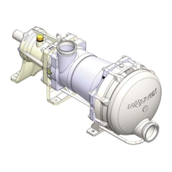
H-FLO 65
Constructions S & HP
WARRANTY :
INSTRUCTIONS 1013-H00 e
Section
1013
Effective
November 2019
Replaces
July 2019
Original instructions
INSTALLATION
OPERATION
MAINTENANCE
Your distributor :
Advertisement
Table of Contents

Related Manuals for Mouvex H-FLO 65


Summary of Contents for Mouvex H-FLO 65
- Page 1 H‐FLO Series pumps are covered 24 months by warranty within the limits mentioned in our General Sales Conditions. In case of a use other than that mentioned in the Instructions manual, and without preliminary agreement of MOUVEX, warranty will be canceled.
-
Page 2: Table Of Contents
- Acceptable maximal differential pressure : Page • H-FLO 65 S ....7 bar (101 psi)* TABLE OF CONTENTS • H-FLO 65 HP ... . .10 bar (145 psi)* - Maximum pressure jacket ...5 barg (72,50 psig) -
Page 3: Overall Dimensions
1. OVERALL DIMENSIONS NT 1013-H00 11 19 H-FLO 65 S & HP e 3/25... - Page 4 1. OVERALL DIMENSIONS (continued) NT 1013-H00 11 19 H-FLO 65 S & HP e 4/25...
- Page 5 1. OVERALL DIMENSIONS (continued) NT 1013-H00 11 19 H-FLO 65 S & HP e 5/25...
-
Page 6: Installation
Check tightness to avoid accidental air intake. Recommended Suction pipe length Length should be as short as possible. -------------------------------------------------------------------- R = 3 x D minimum L = 10 x D minimum NT 1013-H00 11 19 H-FLO 65 S & HP e 6/25... -
Page 7: Orientation Of The Pump Ports
When looking at the front cover, the direction of rotation will be anti-clockwise. Verification of the correct rotation direction : Turn the pump the wrong way is not dangerous for the pump. NT 1013-H00 11 19 H-FLO 65 S & HP e 7/25... -
Page 8: Protection Of The Pump Installation
The following instructions apply to pumps delivered with a bare shaft or for MOUVEX motor-driven pump units (if the latter have no specific instruction notice). NT 1013-H00 11 19 H-FLO 65 S & HP e 8/25... - Page 9 (if the need arises, use the values given on the overall dimension drawing). For staff and equipment protection, the frame includes a ground connection point that should be used. NT 1013-H00 11 19 H-FLO 65 S & HP e 9/25...
- Page 10 Using electric motors is very common now; however, we strongly advise careful reading of the accompanying ins- truction manual. NT 1013-H00 11 19 H-FLO 65 S & HP e 10/25...
-
Page 11: Utilisation
• discharge pressure : pump is completely stopped before closing the valves. • H-FLO 65 S ..7 bar (101 psi) • H-FLO 65 HP ..10 bar (145 psi) 3.5 Scrapping... -
Page 12: Clean In Place (Cip) & Sterilisation In Place (Sip)
In this case, a bypass must be used. The bypass valve is adjusted to divide the flow bet- ween the circuit flowing through the H-FLO pump and the bypass circuit. NT 1013-H00 11 19 H-FLO 65 S & HP e 12/25... -
Page 13: Pumps Arranged In Parallel
Cleaning the installation : Max pressure 6 barg (87 psig) H-FLO pump H-FLO pump The H-FLO pump is stopped when cleaning the installa- The pump must not run during this operation. tion. NT 1013-H00 11 19 H-FLO 65 S & HP e 13/25... -
Page 14: Successive Cycles
• 24 Socket wrench • M10 : 30 Nm • 19 - 24 - 30 Open-end spanner • M16 : 90 Nm • 8 Allen key • M20 : 160 Nm NT 1013-H00 11 19 H-FLO 65 S & HP e 14/25... -
Page 15: Opening Of The Pump
Before any dismantling, make sure that the pump has been drained and take the necessary measures to avoid starting-up. No start-up, even accidental, must be allowed. NT 1013-H00 11 19 H-FLO 65 S & HP e 15/25... -
Page 16: Assembly / Dismantling
• Triangular shape on top of piston wall (A), extraction screws 39306. • Small steps at piston wall base (B). • Remove the cylinder 39201 and its seals 39113A. NT 1013-H00 11 19 H-FLO 65 S & HP e 16/25... - Page 17 Piston must then look as follows : disc wall edges. Even if it shows wearing signs, do not retouch any surface of the cylinder by any mean as it can degrade pump performance and reliability. NT 1013-H00 11 19 H-FLO 65 S & HP e 17/25...
-
Page 18: Assembly Of Cylinder/Piston
• Fit the cylinder / piston set to the bottom of the centering, ali- injuries or material gning the index 39118 correctly with the notch in the main body. damages. Lever Loctite ® is a registered trademark. NT 1013-H00 11 19 H-FLO 65 S & HP e 18/25... -
Page 19: Changing The Lip Seal
• Fit 2 new seals 39608 and 39608A, one on each side of the cover, lip directed towards the interior of the transmission. * Standard oils provided by MOUVEX (Safety data sheet is supplied on inquiery) : CS05 Food synthetic oil CS23 Silicone free oil for transmission * Other oil provided by customer. -
Page 20: Changing The Orientation Of The Ports
• Make sure that the seal 39205 is secured in its housing. Secure it with a grease that is compatible with the transferred product if necessary. Loctite ® is a registered trademark. NT 1013-H00 11 19 H-FLO 65 S & HP e 20/25... -
Page 21: Draining Of Bearing
• Oil level : Any level visible in the height of oil level indicator 39772 is acceptable. • Screw back the breather 39715. * Standard oils provided by MOUVEX (Safety data sheet is supplied on inquiery) : CS05 Food synthetic oil CS23 Silicone free oil for transmission * Other oil provided by customer. -
Page 22: Storage
This protection should also prevent condensation. The pump should be turned a few revolutions manually every two months. NT 1013-H00 11 19 H-FLO 65 S & HP e 22/25... -
Page 23: Troubleshooting
(the piston bushings are worn, worn piston and cylinder, broken piston wear compensation springs, worn partition, broken shaft). NT 1013-H00 11 19 H-FLO 65 S & HP e 23/25... - Page 24 (faulty alignment, deformation of the chassis, stress exerted by the piping on the flanges, seizing, etc.). Excessive consumption of electricity can also be due to a poor motor connection (e.g. a 3 phase motor operating on 2 phases). NT 1013-H00 11 19 H-FLO 65 S & HP e 24/25...
-
Page 25: Certificate Of Conformity
13. CERTIFICATE OF CONFORMITY NT 1013-H00 11 19 H-FLO 65 S & HP e 25/25...
Need help?
Do you have a question about the H-FLO 65 and is the answer not in the manual?
Questions and answers