Table of Contents
Advertisement
Quick Links
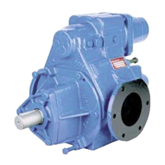
CC8-80 F - CC8-100 F
CC8 Series pumps are covered 24 months by warranty within the limits mentioned in our General Sales Conditions.
In case of a use other than that mentioned in the Instructions manual, and without preliminary agreement of MOUVEX,
warranty will be canceled.
Z.I. La Plaine des Isles - F 89000 AUXERRE - FRANCE
Tel. : +33 (0)3.86.49.86.30 - Fax : +33 (0)3.86.49.87.17
contact@mouvex.com - www.mouvex.com
pumps
WARRANTY :
INSTRUCTIONS 1010-L00 e
Section
1010
Effective
March 2018
Replaces
March 2017
Original instructions
INSTALLATION
OPERATION
MAINTENANCE
Your distributor :
Advertisement
Table of Contents

Related Manuals for Mouvex CC8-80 F


Summary of Contents for Mouvex CC8-80 F
- Page 1 CC8 Series pumps are covered 24 months by warranty within the limits mentioned in our General Sales Conditions. In case of a use other than that mentioned in the Instructions manual, and without preliminary agreement of MOUVEX, warranty will be canceled.
-
Page 2: Table Of Contents
17. SCRAPPING ....... . .16 18. CERTIFICATE OF CONFORMITY ....17 NT 1010-L00 03 18 CC8-80 F - CC8-100 F pumps e 2/17... -
Page 3: Presentation
Viscosity < 40 cSt 580 à 1000 The pumps CC8-80 F and CC8-100 F can work at a pressure equal to 8 bar. They are normally delivered with spring (4 or 8 bar) adjusted at 4 bar. When requested, they can be delivered with a 8 bar spring adjusted at the maximum pressure of use. -
Page 4: Overall Dimensions
3. OVERALL DIMENSIONS NT 1010-L00 03 18 CC8-80 F - CC8-100 F pumps e 4/17... -
Page 5: Installation
4.6 Bypass setting The bypass must be set depending on the needs and the limitations of the installation. NT 1010-L00 03 18 CC8-80 F - CC8-100 F pumps e 5/17... -
Page 6: Direct Drive By Motor
REMINDER : You cannot rely on the coupling to compensate for mis- alignment. NEVER START A UNIT IF THE COUPLING ALIGNMENT IS INCORRECT. THIS WILL RENDER OUR WARRANTY INVALID. NT 1010-L00 03 18 CC8-80 F - CC8-100 F pumps e 6/17... -
Page 7: Electric Motors
TY DAMAGE OR DEATH. Do not operate without guard in place. 6. DRIVE BY POWER TAKE OFF Refer to Instructions NT 1010-B00 CC8 CC10 CC20 PUMPS RIVEN BY POWER TAKE OFF NT 1010-L00 03 18 CC8-80 F - CC8-100 F pumps e 7/17... -
Page 8: Use
In the case of liquids containing particles settling on shut-down, it is necessary to make sure the consistency of the deposit will not impede restarting the pump. NT 1010-L00 03 18 CC8-80 F - CC8-100 F pumps e 8/17... -
Page 9: Protection From Frost
• Create an air entering on the suction side during 30 seconds. • Stop the pump and make sure no liquid is coming back > pump has to be closed. NT 1010-L00 03 18 CC8-80 F - CC8-100 F pumps e 9/17... -
Page 10: Necessary Tools
Before any dismantling, make sure that the pump has been drained and take all the necessary precautions to prevent it from star- ting up. The pump must not start up, even accidentally. NT 1010-L00 03 18 CC8-80 F - CC8-100 F pumps e 10/17... -
Page 11: Side Opposite To Drive System
Screw the 2 screws 411 with their nuts 412 in the bosses. Replace the screws 410. Remove the cover 712. Replace the circlip 537. Replace the shaft protector 712 with its o’ring 714 after check condition of seal. NT 1010-L00 03 18 CC8-80 F - CC8-100 F pumps e 11/17... -
Page 12: Assembly Of Flange For Hydraulic Trunk
Refit the vane (new if necessary) respecting the direction of assembly. Proceed so on for each vane. Reassemble the pump and check that it rotates freely when turned by hand. NT 1010-L00 03 18 CC8-80 F - CC8-100 F pumps e 12/17... -
Page 13: Changing Mechanical Seal And Ball Bearings13
Set bypass at desired pressure setting by tightening nut 834 with the same number of rotations as counted during Remove the valve 823 by pulling its cylindrical section with dismounting. the fingers. Check condition of bypass. NT 1010-L00 03 18 CC8-80 F - CC8-100 F pumps e 13/17... -
Page 14: Pneumatic Bypass
Set the bypass by screwing the nut 834 with the same turn numbers noticed. ln some cases, a light leak between the membrane 813 and the plate 802 is acceptable. NT 1010-L00 03 18 CC8-80 F - CC8-100 F pumps e 14/17... -
Page 15: Maintenance
- Pump damaged (see § Abnormal noise - Pump damaged due to passage of foreign matter). • Bypass valve hammer on its seat due to incorrect adjustment of the spring’s tension. NT 1010-L00 03 18 CC8-80 F - CC8-100 F pumps e 15/17... -
Page 16: Storage
The pump must be scrapped in compliance with the regulations During this operation, particular care must be paid to the drai- in force. nage stages of the pump (pumped product). NT 1010-L00 03 18 CC8-80 F - CC8-100 F pumps e 16/17... -
Page 17: Certificate Of Conformity
18. CERTIFICATE OF CONFORMITY NT 1010-L00 03 18 CC8-80 F - CC8-100 F pumps e 17/17...
Need help?
Do you have a question about the CC8-80 F and is the answer not in the manual?
Questions and answers