Table of Contents
Advertisement
Quick Links
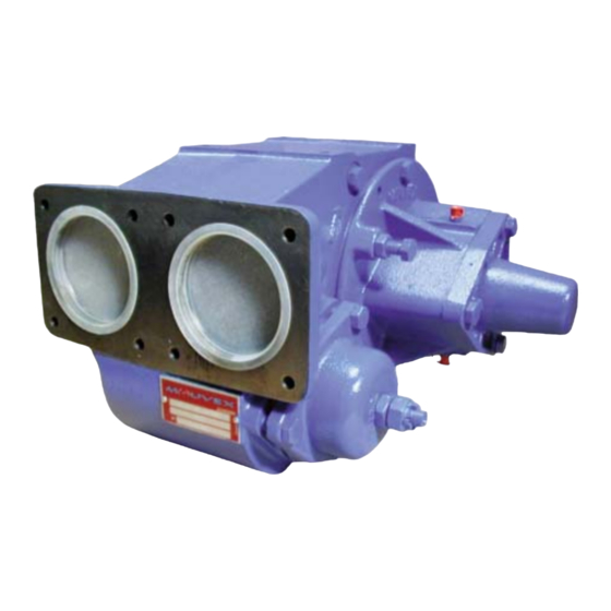
CC8-40 - CC8-50 - CC8-65
CC8 Series pumps are covered 24 months by warranty within the limits mentioned in our General Sales Conditions.
In case of a use other than that mentioned in the Instructions manual, and without preliminary agreement of MOUVEX,
warranty will be canceled.
Z.I. La Plaine des Isles - F 89000 AUXERRE - FRANCE
Tel. : +33 (0)3.86.49.86.30 - Fax : +33 (0)3.86.49.87.17
contact.mouvex@psgdover.com - www.mouvex.com
pumps
Constructions A & C
WARRANTY :
INSTRUCTIONS 1010-D00 e
Section
1010
Effective
May 2020
Replaces
March 2018
Original instructions
INSTALLATION
OPERATION
MAINTENANCE
Your distributor :
Advertisement
Table of Contents

Related Manuals for Mouvex CC8-40


Summary of Contents for Mouvex CC8-40
- Page 1 CC8 Series pumps are covered 24 months by warranty within the limits mentioned in our General Sales Conditions. In case of a use other than that mentioned in the Instructions manual, and without preliminary agreement of MOUVEX, warranty will be canceled.
-
Page 2: Table Of Contents
16. CERTIFICATE OF CONFORMITY ....20 NT 1010-D00 05 20 CC8-40 - CC8-50 - CC8-65 A & C pumps e 2/20... -
Page 3: Operating Limits
When requested, they can be delivered with a 8 bar spring adjusted at the maximum pressure of use. Temperature range allowed : Construction A ..-20°C to +80°C Construction C..-20°C to +170°C Products authorised : Clean petroleum product Other products: Contact us NT 1010-D00 05 20 CC8-40 - CC8-50 - CC8-65 A & C pumps e 3/20... -
Page 4: Overall Dimensions
2. OVERALL DIMENSIONS NT 1010-D00 05 20 CC8-40 - CC8-50 - CC8-65 A & C pumps e 4/20... - Page 5 2. OVERALL DIMENSIONS (continued) NT 1010-D00 05 20 CC8-40 - CC8-50 - CC8-65 A & C pumps e 5/20...
- Page 6 2. OVERALL DIMENSIONS (continued) NT 1010-D00 05 20 CC8-40 - CC8-50 - CC8-65 A & C pumps e 6/20...
- Page 7 2. OVERALL DIMENSIONS (continued) NT 1010-D00 05 20 CC8-40 - CC8-50 - CC8-65 A & C pumps e 7/20...
-
Page 8: Installation
NT 1010-D00 05 20 CC8-40 - CC8-50 - CC8-65 A & C pumps e 8/20... -
Page 9: Bypass Setting
• Check on the installation the pump gives the right pres- sure (using a manometer) with a closed valve on the 8,5 (1) discharge line. 9,5 (1) (1) Pressure limited to 8 bar, prohibited zone NT 1010-D00 05 20 CC8-40 - CC8-50 - CC8-65 A & C pumps e 9/20... -
Page 10: Direct Drive By Motor
You cannot rely on the coupling to compensate for mis- alignment. NEVER START A UNIT IF THE COUPLING ALIGNMENT IS INCORRECT. THIS WILL RENDER OUR WARRANTY INVALID. NT 1010-D00 05 20 CC8-40 - CC8-50 - CC8-65 A & C pumps e 10/20... -
Page 11: Electric Motors
Do not operate without guard in place. 5. DRIVE BY POWER TAKE OFF Refer to Instructions NT 1010-B00 CC8 CC10 CC20 PUMPS RIVEN BY POWER TAKE OFF NT 1010-D00 05 20 CC8-40 - CC8-50 - CC8-65 A & C pumps e 11/20... -
Page 12: Use
In the case of liquids containing particles settling on shut-down, it is necessary to make sure the consistency of the deposit will not impede restarting the pump. NT 1010-D00 05 20 CC8-40 - CC8-50 - CC8-65 A & C pumps e 12/20... -
Page 13: Protection From Frost
• Stop the pump and make sure no liquid is coming back > pump has to be closed. Step 2 : • Defect or in complement, drain by the bottom plug. Drain plug NT 1010-D00 05 20 CC8-40 - CC8-50 - CC8-65 A & C pumps e 13/20... -
Page 14: Necessary Tools
Before any dismantling, make sure that the pump has been drained and take all the necessary precautions to prevent it from star- ting up. The pump must not start up, even accidentally. NT 1010-D00 05 20 CC8-40 - CC8-50 - CC8-65 A & C pumps e 14/20... -
Page 15: Dismantling On Side Opposite To Drive System
SIDE OPPOSITE TO DRIVE SYSTEM. 8.4 Assembly of flange for hydraulic trunk Refer to Instructions NT 1010-K00 A SSEMBLY OF FLANGE CC8 CC10. FOR HYDRAULIC TRUNK ON PUMP NT 1010-D00 05 20 CC8-40 - CC8-50 - CC8-65 A & C pumps e 15/20... -
Page 16: Changing The Vanes
708 (if present). Place the second bearing 703 so it is supported on the spacer 734. Refit the end plate (see § REASSEMBLY OF THE PUMP). NT 1010-D00 05 20 CC8-40 - CC8-50 - CC8-65 A & C pumps e 16/20... -
Page 17: Bypass
Ball bearing are lubricated for life and don’t require any grease adding. 12.2 Inspection of the vanes Pump CC8-40 CC8-50 CC8-65 Original height h Change when h < to 30,5 32,5 35,5 NT 1010-D00 05 20 CC8-40 - CC8-50 - CC8-65 A & C pumps e 17/20... -
Page 18: Troubleshooting
- Pump damaged (see § Abnormal noise - Pump damaged due to passage of foreign matter). • Bypass valve hammer on its seat due to incorrect adjustment of the spring’s tension. NT 1010-D00 05 20 CC8-40 - CC8-50 - CC8-65 A & C pumps e 18/20... -
Page 19: Storage
The pump must be scrapped in compliance with the regulations During this operation, particular care must be paid to the drai- in force. nage stages of the pump (pumped product). NT 1010-D00 05 20 CC8-40 - CC8-50 - CC8-65 A & C pumps e 19/20... -
Page 20: Certificate Of Conformity
16. CERTIFICATE OF CONFORMITY NT 1010-D00 05 20 CC8-40 - CC8-50 - CC8-65 A & C pumps e 20/20...
Need help?
Do you have a question about the CC8-40 and is the answer not in the manual?
Questions and answers