
Related Manuals for Huck Howmet Aerospace BobTail BTT25


Summary of Contents for Huck Howmet Aerospace BobTail BTT25
-
Page 1: Table Of Contents
BTT25 Table of Contents EC/UKCA Declaration of Conformity Safety Instructions 3 - 5 Description BobTail Hydraulic ® Principle of Operation Installation Tool Program Cycle Tool Specifications 6 - 7 Instruction Manual Spare Parts and Accessories 7 - 8 Maintenance 8 - 9 Tool Disassembly Tool Assembly Preparation for Use... -
Page 2: Ec/Ukca Declaration Of Conformity
BTT25 BobTail® Hydraulic Installation Tool (HK1098) EC Declaration of Conformity UKCA Declaration of Conformity Manufacturer: Manufacturer: Huck International, LLC, Industrial Products Group, Huck International, LLC, Industrial Products Group, 1 Corporate Drive, Kingston, NY, 12401, USA 1 Corporate Drive, Kingston, NY, 12401, USA Description of Machinery:... - Page 3 • This high pressure hose is not to be used other than assembled in a genuine HUCK tool or hose assembly or used as a replacement hose of a genuine HUCK tool or hose assembly.
-
Page 4: Safety Instructions
BTT25 BobTail® Hydraulic Installation Tool (HK1098) Safety Instructions I. GENERAL SAFETY RULES: 2. Disconnect the assembly power tool from energy 1. A half hour long hands-on training session with source when changing inserted tools or accessories. qualified personnel is recommended before using 3. -
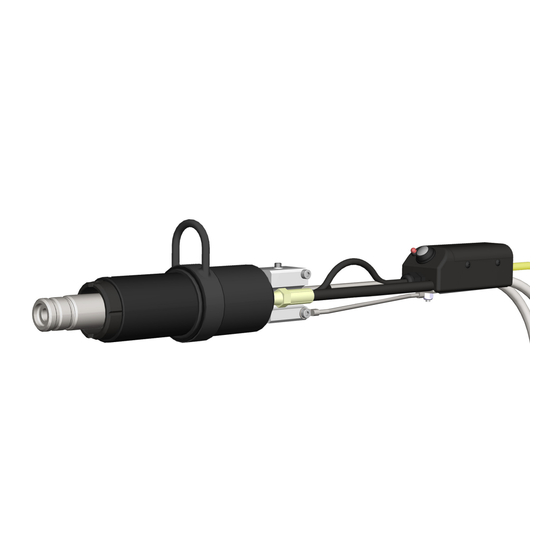
Page 5: Description
Use HUCK Set-up Gauge with actuator rod for detecting the presence of a fastener (P/N T-124833CE) to check and set pressures. The gauge is in the puller, a trigger switch assembly, and come complete available separately and includes instructions for use. -
Page 6: Principle Of Operation
Specifications Hose Kits: Use only genuine HUCK Hose Kits rated at 10,000 psi working pressure. Hydraulic fluid: Hydraulic fluid shall meet DEXRON III, DEXRON VI, MERCON, Allison C-4 or equivalent ATF specifications. Fire resistant fluid may be used if it’s an ester based fluid such as Quintolubric HFD or equivalent. -
Page 7: Spare Parts And Accessories
BTT25 BobTail® Hydraulic Installation Tool (HK1098) Specifications (continued) DESCRIPTION DETAIL DESCRIPTION DETAIL POWER SOURCE Huck Powerig® Hydraulic Unit MAX FLOW RATE 2 gpm 7.57 l/m MIN OPERATING TEMP 32 ° F STROKE 1.63 inches 0 ° C 4.1 cm MAX OPERATING TEMP 125 ° F WEIGHT (approximate) 8 lbs 51.7 °... -
Page 8: Maintenance
BTT25 BobTail® Hydraulic Installation Tool (HK1098) Spare Parts & Accessories (continued) 128457-* Cable Assembly Noses for BTT25 (Pressure Transmitter) NOSE DESCRIPTION PART # DETAILS PART # DETAILS BTT25 12MM BT 99-7850 128457-10 Cable Asm, Press Xmitter 10 FT 12MM BT BTT25 CUT 99-7850CX Cutter Nose 128457-25 Cable Asm, Press Xmitter 25 FT... -
Page 9: Tool Disassembly
BTT25 BobTail® Hydraulic Installation Tool (HK1098) Maintenance (continued) PREVENTIVE MAINTENANCE • Max contamination level: NAS 1638 class 9, or ISO CODE 18/15, or SAE level 6. SYSTEM INSPECTION POWERIG MAINTENANCE Operating efficiency of the tool is directly related to the Refer to the applicable Powerig instruction manual. -
Page 10: Tool Assembly
Hydraulic Unit before connecting Tool’s switch available independently, is recommended. control cord to unit. If not connected in this order, 2. Use only a Huck Powerig 918, 940, or equivalent severe personal Injury may occur. that has been prepared for operation per applicable instruction manual. -
Page 11: Operating Instructions
Sticker Locations HUCK hydraulic tools come labeled with stickers which contain safety and pressure settings information. Stickers must remain on the tool and readable. If a sticker becomes damaged or worn, or if it has been removed from the tool, or when replacing the hydraulic Cylinder, it must be ordered and placed in the locations shown. -
Page 12: Tool-To-Powerig ® Setup
10. Set the PULL and RETURN pressures on the Powerig Load Test Fastener Photo A using Huck Gauge P/N T-124833CE and TABLE 1. Cell 11. Using a load cell (Photo A) or a skidmore, and a test fastener in the tool, energize the Powerig using a trigger switch. -
Page 13: Assembly Of Nptf Threaded Components
BTT25 BobTail® Hydraulic Installation Tool (HK1098) Assembly of NPTF Threaded Components AIR FITTINGS 4) Final thread engagement can be checked (optional) 1) Apply TEFLON® stick to male threads which do by measuring the dimension from the flange of male not have pre-applied sealant per manufacturer’s fitting to the end of the thread before assembly recommendations. -
Page 14: Component Drawings
BTT25 BobTail® Hydraulic Installation Tool (HK1098) Component Drawings BTT25 Tool Assembly Figure 6 590517 590512-15 HUCK Trademark & Year of Manufacture Sticker CE & Warning Sticker, 8400 PSI 128781 Trigger & Terminal Box Assembly 128700 (see Figure 8.1) Tool Assembly... - Page 15 BTT25 BobTail® Hydraulic Installation Tool (HK1098) Component Drawings continued... 128700 Subassemblies Figure 8 128698 128696 Main Housing Assembly Rear Piston Assembly 128697 121343 506077 Rear Piston 501108 Lockscrew O-Ring Back-up Ring 128699 501138 500814 505917 Main Housing Back-up Ring (2) Polyseal O-Ring (2) 128694...
-
Page 16: Wiring Instructions
BTT25 BobTail® Hydraulic Installation Tool (HK1098) Component Drawings continued... 128745 Limit Switch Housing Assembly Figure 8.2 500048 Cap Screw 500166 Flat Washer 128747 128746 507570 Limit Switch Limit Switch 128749 Switch Plate Button-head Cap Screw (2) Upper Housing Lower Housing Apply Loc te 243 or equivalent, 508360 Spring per manufacturer’s instruc ons. -
Page 17: Puller Wear And/Or Replacement
BTT25 BobTail® Hydraulic Installation Tool (HK1098) Puller Wear and/or Replacement a) Insert the spring into the piston. TOOLS NEEDED b) Insert the actuator rod into the piston. 1. Interchangeable Anvil Micrometers or Dial Calipers c) Insert the rod guide into the piston. 2. -
Page 18: Nose Assembly Installation And Removal
BTT25 BobTail® Hydraulic Installation Tool (HK1098) Nose Assembly & Disassembly Instructions Assembly Instructions Anvil Holder 1. If tool is equipped with a switch, install spring, actuator rod, and rod guide into piston prior to installing puller. 2. Thread puller onto forward piston until machined alignment notch Anvil Assembly on puller hub is in line with face of forward gland when piston is fully retracted (in pull position). -
Page 19: Warranties
Huck International, Inc. warrants that its installation tools and Powerig® hydraulic power sources manufactured Huck shall not be liable for any loss or damage resulting after December 1, 2016 shall be free from defects in from delays or non-fulfillment of orders owing to strikes,... - Page 20 1 Corporate Drive, Kingston, NY 12401 implied, or statutory; all warranties are contained Tel: 800-431-3091 • Fax: 845-334-7333 only in Huck’s written quotations, acknowledgments, and/or purchase www.hfsindustrial.com/us orders. It is recommended the user secure specific, up-to-date data and information regarding each application and/or use of such products.
Need help?
Do you have a question about the Howmet Aerospace BobTail BTT25 and is the answer not in the manual?
Questions and answers