
Subscribe to Our Youtube Channel
Related Manuals for Huck BOBTAIL


Summary of Contents for Huck BOBTAIL
- Page 1 NSTRUCTION ANUAL AIL ® NSTALLATION YSTEM SFBTT15 SFBTT15 November 12, 2014 HK1151...
-
Page 2: Ec Declaration Of Conformity
SFBTT15 BOBTAIL® Hydraulic Tool Alcoa Fastening Systems (HK1151) -
Page 3: Table Of Contents
SFBTT15 BOBTAIL® Hydraulic Tool Alcoa Fastening Systems (HK1151) ONTENTS ONTENTS EC D ......2 ECLARATION OF ONFORMITY ......... .4-5 AFETY . -
Page 4: Safety
Huck equipment. 2. Disconnect the assembly power tool from energy source 2. Huck equipment must be maintained in a safe working con- when changing inserted tools or accessories. dition at all times. Tools and hoses should be inspected at the 3. - Page 5 SFBTT15 BOBTAIL® Hydraulic Tool Alcoa Fastening Systems (HK1151) AFETY NSTRUCTIONS CONTINUED AFETY NSTRUCTIONS CONTINUED IV. REPETITIVE MOTION HAZARDS: VIII. VIBRATION HAZARDS: 1. When using assembly power tool, the operator can experi- 1. Exposure to vibration can cause disabling damage to the ence discomfort in the hands, arms, shoulders, neck or nerves and blood supply to the hands and arms.
-
Page 6: Principle Of Operation
PECIFICATIONS PECIFICATIONS IGURE Power Source: Huck POWERIG Hydraulic Unit 3.74 2.63 (9.5) Hose Kits: Use only genuine HUCK Hose Kits rated @ (6.7) 3.27 10,000 psi working pressure. (1.2) (8.3) Hydraulic Fluid: Hydraulic fluid shall meet DEXRON III, DEXRON VI, MERCON, Allison C‐4 or equivalent ATF specifications. -
Page 7: Reparation For Se
RETURN, AND ARE NOT EQUIPPED 4. Connect PULL pressure hose, with coupler nipple, into WITH RELIEF VALVES ARE SPECIFICAL- port “P” of tool. Use only with HUCK supplied hoses LY NOT RECOMMENDED AND MAY BE rated at 10,000 psi or greater. Check trigger assembly DANGEROUS. -
Page 8: Ool To Owerig Et Up
Powerig. 5. Set Pull and Return pressures on Powerig and WARNING: Only use compatible equipment Relief Valve using Huck Gage P/N: T-124833CE with this tool. and Table 1. NOTE: To decrease Relief Valve pressure, turn the Relief Valve handle gradually counterclock- 6. -
Page 9: Perating Nstructions
2. Put BOBTAIL pin in hole. wear approved eye and ear protection. Ensure adequate clearance for Operator’s hands 3. Slide BOBTAIL collar over pin. (The flanged end of the before proceeding with fastener installation. collar must be towards the pieces being fastened.) ■... -
Page 10: Aintenance
Threadmate™ is available from Huck in a 4oz. tube as part number 508517. NOSE ASSEMBLY MAINTENANCE Daily cleaning of the nose assembly is recommended. -
Page 11: Disassembly And Assembly Preparation
Threadmate™, which grooves of the jaws. Apply anti-seize lubricant, part is available from Huck in a 4oz. tube as part number 505565, to outside of puller and inside of number 508517. DO NOT use Teflon tape on anvil. -
Page 12: Tool Assembly Drawings With Part Numbers
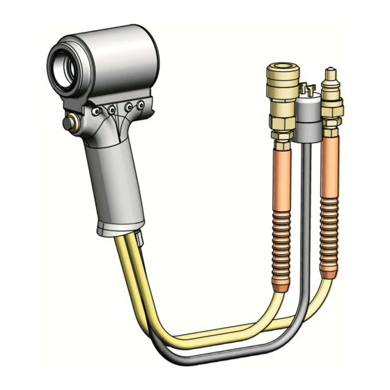
SFBTT15 BOBTAIL® Hydraulic Tool Alcoa Fastening Systems (HK1151) SSEMBLY RAWING ANDLE SSEMBLY RAWING ANDLE ORDER OF DISASSEMBLY: IGURE Remove 7 Screws “A” & “B” 501152 Back-up Ring 130211 Cylinder Assy Remove Aft and Plug Covers “C” & “D” 503848 O-Ring Remove Locking Disc “E”... - Page 13 SFBTT15 BOBTAIL® Hydraulic Tool Alcoa Fastening Systems (HK1151) SSEMBLY RAWING OSES IRINGS SSEMBLY RAWING OSES IRINGS IGURE 128938 Cord Assy 110439 Female Hydraulic Coupler 110438 Male Hydraulic Coupler Apply Loctite 242, HUCK p/n 505016, to these threaded joints Apply Loctite 242, per manufacturer’s...
-
Page 14: Ptional Quipment
SFBTT15 BOBTAIL® Hydraulic Tool Alcoa Fastening Systems (HK1151) PTIONAL QUIPMENT PTIONAL QUIPMENT To maintain CE conformity, only CE compatible equipment should be used with these tools. Installation tools and nose assemblies are the only CE components unless otherwise noted. Controls and other hardware shown in the manual are for domestic use only. - Page 15 Huck shall not be liable for any loss or damage result- THERE ARE NO WARRANTIES WHICH EXTEND ing from delays or nonfulfillment of orders owing to...
- Page 16 International. Huck provides technical assistance ments, and/or purchase orders. It is recommend‐ ™ For the Long Haul regarding the use and application of Huck fasten‐ ed that the user secure specific, up‐to‐date data ers and tooling. and information regarding each application and/or use of such products.
Need help?
Do you have a question about the BOBTAIL and is the answer not in the manual?
Questions and answers