Table of Contents
Advertisement
Quick Links
Hitachi Advanced Server HA805 G3 Series
User Guide
This document is for the person who installs, administers, and troubleshoots servers and storage
systems. Hitachi Vantara assumes you are qualified in the servicing of computer equipment and
trained in recognizing hazards in products with hazardous energy levels.
MK-90HAS8032-01
October 2023
Advertisement
Table of Contents

Related Manuals for Hitachi HA805 G3 Series


Summary of Contents for Hitachi HA805 G3 Series
- Page 1 User Guide This document is for the person who installs, administers, and troubleshoots servers and storage systems. Hitachi Vantara assumes you are qualified in the servicing of computer equipment and trained in recognizing hazards in products with hazardous energy levels.
- Page 2 Hitachi, Ltd., or Hitachi Vantara LLC (collectively “Hitachi”). Licensee may make copies of the Materials provided that any such copy is: (i) created as an essential step in utilization of the Software as licensed and is used in no other manner;...
-
Page 3: Table Of Contents
Contents Component identification..............7 Front panel components................................7 iLO Service Port..................................8 Front panel LEDs and buttons..............................9 Server UID LED..................................10 Using the UID button to view the Server Health Summary..................10 Front panel LED power fault codes.......................... 11 Rear panel components. - Page 4 Operations................39 Remove the front bezel................................39 Power down the server................................40 Open the cable management arm............................40 Extend the server out of the rack............................41 Remove the server from the rack............................42 Remove the access panel................................. 45 Remove the middle cover.
- Page 5 Memory option..................................113 SmartMemory speed and population information....................114 DIMM installation guidelines........................... 114 Installing a DIMM..............................114 Riser cage options.................................... 117 Installing the one-slot secondary riser cage......................117 NS204i-u + low-profile riser cage option..........................120 Installing the NS204i-u + secondary low-profile riser cage.
- Page 6 Drive power cabling..............................196 Energy pack cabling..............................199 Storage controller backup power cabling......................200 Optical drive cabling................................201 M.2 SSD pass-through card cabling........................... 202 NS204i Boot Device cabling..............................203 Pump signal cabling for the liquid cooling heatsink......................203 OCP bandwidth upgrade cabling.
- Page 7 Getting help Hitachi Vantara Support Connect is the destination for technical support of products and solutions sold by Hitachi Vantara. To contact technical support, log on to Hitachi Vantara Support Connect for contact information: https://support.hitachivantara.com/en_us/contact-us.html.
-
Page 8: Component Identification
Component identification This chapter describes the external and internal server features and components. Front panel components 4 LFF drive configuration Item Description Optical drive (optional) Serial number/ iLO information pull tab DisplayPort 1.1a (optional) USB 2.0 port (optional) USB 3.2 Gen1 port iLO Service Port 4 LFF drives (optional) The serial number/ iLO information pull tab is double-sided. -
Page 9: Ilo Service Port
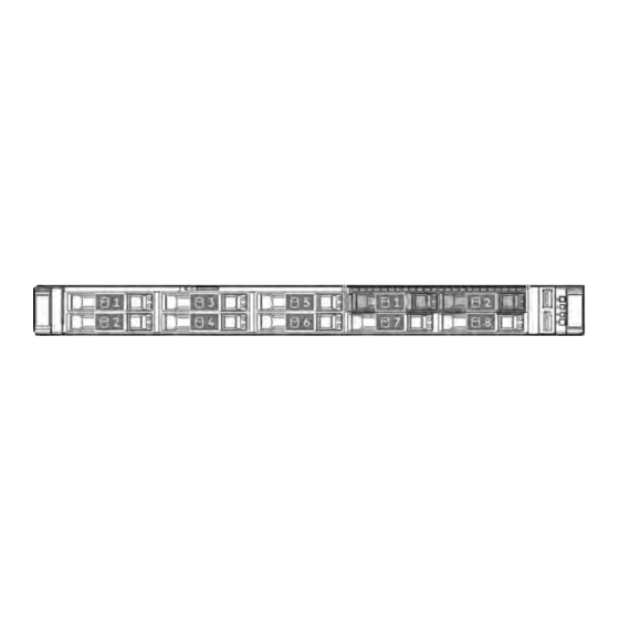
Item Description Serial number/ iLO information pull tab Optical drive cage assembly (optional) 2 SFF side-by-side drive cage assembly (optional) iLO Service Port USB 3.2 Gen1 port 8 SFF drives (optional) 1 serial number/ iLO information pull tab is double-sided. One side shows the server serial number and the customer asset tag label. The other side shows the default iLO account information. -
Page 10: Front Panel Leds And Buttons
When you use this feature, the connected USB flash drive is not accessible by the host operating system. • Connect a client (such as a laptop) with a supported USB to Ethernet adapter to access the following: ◦ iLO web interface ◦... -
Page 11: Server Uid Led
Item Description Status Definition Flashing red System critical NIC status LED Solid green Linked to network Flashing green Network active No network activity UID button/LED Solid blue Activated Flashing blue • 1 flash per second—Remote management or firmware upgrade in progress •... -
Page 12: Front Panel Led Power Fault Codes
Front panel LED power fault codes The following table provides a list of power fault codes, and the subsystems that are affected. Not all power faults are used by all servers. Subsystem LED behavior System board 1 flash Processor 2 flashes Memory 3 flashes Riser board PCIe slots... -
Page 13: Display Device Setup
Item Description Flexible Slot power supply 2 (optional) Flexible Slot power supply 1 VGA port Slot 22 OCP PCIe5 x8 Serial port (optional) iLO management port USB 3.2 Gen1 ports Slot 21 OCP PCIe5 x8 This riser slot is in the primary riser cage. This option is in the NS204i-u + low-profile riser cage. -
Page 14: System Board Components
Item Status Definition Power supply Solid green The power supply is operating normally. One or more of the following conditions exists: • Power is unavailable • Power supply failure • Power supply is in standby mode • Power supply error iLO link Solid green Network link... - Page 15 Item Description Serial port connector Stacked, dual USB 3.2 Gen1 ports Slot 21 OCP x16 upgrade connector Front USB and DisplayPort connector Primary riser connector Slot 21 OCP storage backup power connector Front I/O connector NVMe port 9A Pump-cold plate signal connector System battery GPU riser power connector NVMe/SATA port 1A...
-
Page 16: System Maintenance Switch Descriptions
Item Description Fan connector 5 NVMe port 3A Fan connector 4 NVMe port 4A NVMe port 5A Fan connector 3 NVMe port 6A Fan connector 2 NVMe port 7A Fan connector 1 NVMe port 8A NS204i-u signal connector Energy pack connector Drive backplane / Graphics card power connector C (J9019) Drive backplane/Graphics card power connector A (J9017) Drive backplane/Graphics card power connector B (J9018) -
Page 17: Dimm Label Identification
Position Default Function Reserved • Off—Power-on password is enabled. • On—Power-on password is disabled. 1,2 3 • Off—No function • On—Restore default manufacturing settings Reserved Reserved Reserved Reserved Reserved Reserved To access the redundant ROM, set S1, S5, and S6 to On. When the system maintenance switch position 6 is set to the On position, the system is prepared to restore all configuration settings to their manufacturing defaults. -
Page 18: Dimm Slot Numbering
Item Description Example Capacity 16 GB 32 GB 64 GB 128 GB 256 GB Rank 1R—Single rank 2R—Dual rank 4R—Quad rank 8R— Octal rank Data width on DRAM x4—4-bit x8—8-bit Memory generation PC5—DDR5 Maximum memory speed 4800 MT/s CAS latency B—42-42-42 B—50-42-42 (for 128 GB and 256 GB capacities) DIMM type... -
Page 19: Processor And Socket Components
Processor and socket components Item Description Processor socket Pin field cover cap Processor carrier Rail frame lift tabs Retention frame screw (T-20) Retention frame Rail frame Processor Riser board components Primary / secondary one-slot PCIe5 x16 riser Item Description Controller storage backup power connector Component identification... -
Page 20: Pcie5 Slot Description
Item Slot type Supported form factors Slot Slot number power 1 / 2 PCIe5 x16 (16, 8, 4, 1) slot 75 W • Full-height, half-length • Half-height, half-length (low-profile) Secondary low-profile one-slot PCIe5 x16 riser Item Description Controller storage backup power connector Item Slot Slot type... -
Page 21: Basic Drive Led Definitions
Item Description Definition PCI Express version Each PCIe version corresponds to a specific data transfer rate between the processor and peripheral devices. Generally, a version update corresponds to an increase in transfer rate. • PCIe 1.x • PCIe 2.x • PCIe 3.x •... - Page 22 SFF basic drive carrier The SFF basic drive carrier supports hot-plug SAS, SATA, or U.3 NVMe drives. Item State Definition Fault/Locate Solid amber This drive has failed, is unsupported, or is invalid. Solid blue The drive is operating normally and being identified by a management application.
-
Page 23: Edsff Ssd Led Definitions
Item State Definition Flashing green (4 flashes The drive is operating normally and has activity. per second) The drive is not configured by a RAID controller or is a spare drive. EDSFF SSD LED definitions This server supports hot-plug Enterprise and Data Center Standard Form Factor (EDSFF) drives. Specifically, E3.S PCIe5 NVMe SSDs. -
Page 24: Lff Drive Bay Numbering
LFF drive bay numbering The following drive backplane options are supported in the LFF drive configurations: • 4 LFF 12G x1 SAS UBM2 LP • 4 LFF 12G x1 SAS UBM6 LP For more information on the drive backplane description, see Drive backplane naming. In the LFF drive configuration: •... -
Page 25: E3.S Drive Bay Numbering
This topic explains the features represented in the drive backplane naming. This naming convention was adopted starting in the Hitachi Vantara G3 server release. Your server might not support all the features listed in this topic. For server-specific support information, see the server guides: Drive backplane support, see Drive bay numbering. -
Page 26: Fan Numbering
Item Description Values Port link width and interface x1 NVMe/SAS—U.3 NVMe, SAS, or SATA x4 NVMe/SAS—U.3 NVMe, SAS, or SATA x4 NVMe—U.2 NVMe x4 NVMe—E3.S Universal backplane manager (UBM) options UBM2—Segregated SAS/SATA UBM3 or UBM6—Converged UBM4 or UBM6—Segregated U.2 NVMe UBM5 or UBM7—EDSFF Drive carrier type BC—Basic carrier (SFF) -
Page 27: Liquid Cooling Options
Maximum Usage Limitation not to exceed five (5) years of operation. After reaching this five (5) years limit, it is required that the liquid cooling heatsink be replaced. Parts and components that Hitachi Vantara determines have reached or exceeded their Maximum Usage Limitation will not be provided, repaired, or replaced under a warranty or service contract. -
Page 28: Dsc-25 2-Port Sfp28 Card Ports And Leds
Item Description Liquid cooling fans (7, single-rotor) Coolant tubes Pump-cold plate Pump signal cable Radiator The liquid cooling heatsink has two pumps for redundancy. DSC-25 2-port SFP28 card ports and LEDs Ports Item Port Description Management port 1GbE RJ45 Network interface port 10/25G SFP+ based Network interface port 10/25G SFP+ based... - Page 29 LEDs The DSP DSC-25 2p SFP28 card is a dual-port, single-slot, half-height, half-length (HHHL) SFP28 network adapter. It has LEDs for Link (L) and Activity (A) for each port. A half-height bracket is shown in the following illustration with SFP28 ports and LEDs. Item Status Description...
-
Page 30: Trusted Platform Module 2.0 Guidelines
Recovery Mode after BitLocker detects a possible compromise of system integrity. • Hitachi Vantara is not liable for blocked data access caused by improper TPM use. For operating instructions, see the documentation for the encryption technology feature provided by the operating system. M.2 SSD pass-through card components The dual-slot M.2 SSD pass-through card option supports both SATA and NVMe SSDs in 2280 and 22110 form factors. -
Page 31: Ns204I-U Boot Device Components
Item Description M.2 SSD slot 1 2280 standoff 22110 standoff SlimSAS port Power connector Retaining latch M.2 SSD slot 2 NS204i-u Boot Device components Item Description Boot device cage M.2 slots Boot device carriers Component identification... -
Page 32: Ns204I-U Boot Device Led Definitions
NS204i-u Boot Device LED definitions Item Status Definition Fault/Locate Solid amber Drive has failed, unsupported, or invalid. Solid blue Drive is operating normally and being identified by a management application. Flashing amber/blue (1 Drive has failed, or a predictive failure alert is received for the drive. flash per second) The drive has also been identified by a management application. -
Page 33: Setup
The Installation Service is part of a suite of deployment services that are designed to give users the peace of mind that comes from knowing that their and Hitachi Vantara-supported products have been installed by a specialist. - Page 34 more information, contact customer support. ◦ Download the Service Pack for Advanced Server (SPV)—SPV is a comprehensive system software and firmware update solution that is delivered as a single ISO image. This solution uses Smart Update Manager (SUM) as the deployment tool.
-
Page 35: Operational Requirements
8. Deploy an OS or virtualization software. 9. After the OS is installed, update the drivers. Operational requirements When preparing the site and planning the installation for the Hitachi Advanced Server HS805 G3, be sure to observe the following general operational requirements: Space and airflow requirements •... -
Page 36: Temperature Requirements
CAUTION: To prevent improper cooling and damage to the equipment, do not block the ventilation openings. When vertical space in the rack is not filled by a server or rack component, the gaps between the components cause changes in airflow through the rack and across the servers. Cover all gaps with blanking panels to maintain proper airflow. CAUTION: Always use blanking panels to fill empty vertical spaces in the rack. -
Page 37: Electrical Grounding Requirements
Electrical grounding requirements The server must be grounded properly for proper operation and safety. In the United States, you must install the equipment in accordance with NFPA 70, National Electric Code Article 250, as well as any local and regional building codes. In Canada, you must install the equipment in accordance with Canadian Standards Association, CSA C22.1, Canadian Electrical Code. -
Page 38: Server Warnings And Cautions
WARNING: To reduce the risk of personal injury or equipment damage when unloading a rack: • At least two people are needed to safely unload the rack from the pallet. An empty 42U rack can weigh as much as 115 kg (253 lb), can stand more than 2.1 m (7 ft) tall, and might become unstable when being moved on its casters. •... -
Page 39: Electrostatic Discharge
CAUTION: Do not operate the server for long periods with the access panel open or removed. Operating the server in this manner results in improper airflow and improper cooling that can lead to thermal damage. Electrostatic discharge Be aware of the precautions you must follow when setting up the system or handling components. A discharge of static electricity from a finger or other conductor may damage system boards or other static-sensitive devices. -
Page 40: Operations
Operations This chapter describes the hardware operations carried out prior to and after installing or removing a hardware component, or performing a server maintenance or troubleshooting procedure. Before performing these hardware operations, review the: Rack warnings and cautions • Server warnings and cautions •... -
Page 41: Power Down The Server
Power down the server Before powering down the server for any upgrade or maintenance procedures, perform a backup of critical server data and programs. IMPORTANT: When the server is in standby mode, auxiliary power is still being provided to the system. To power down the server, use one of the following methods: •... -
Page 42: Extend The Server Out Of The Rack
Extend the server out of the rack Prerequisites Before you perform this procedure, review the Rack warnings and cautions. • • T-25 Torx screwdriver—This tool is required if the shipping screws located inside the chassis ears are secured. About this task WARNING: To reduce the risk of personal injury, be careful when pressing the server rail-release latches. -
Page 43: Remove The Server From The Rack
WARNING: To reduce the risk of personal injury, be careful when pressing the server rail-release latches. The inner rails could pinch your fingers. Press and hold the rear-end rail-release latches (callout 1), and then slide the server out of the rack until it is fully extended (callout 2). - Page 44 ◦ Rack warnings and cautions ◦ Server warnings and cautions • A fully populated server is heavy. Remove the external server components before removing the server from the rack. • T-25 Torx screwdriver—This tool is required if the shipping screws located inside the chassis ears are secured. Procedure 1.
- Page 45 WARNING: To reduce the risk of personal injury, be careful when pressing the server rail-release latches. The inner rails could pinch your fingers. Press and hold the rear-end rail-release latches (callout 1), and then slide the server out of the rack until it is fully extended (callout 2).
-
Page 46: Remove The Access Panel
8. Place the server on a flat, level work surface. Remove the access panel Prerequisites Before you perform this procedure, make sure that you have a T-15 Torx screwdriver available. About this task WARNING: To reduce the risk of personal injury from hot surfaces, allow the drives and the internal system components to cool before touching them. - Page 47 3. Remove all power: a. Disconnect each power cord from the power source. b. Disconnect each power cord from the server. 4. Disconnect all peripheral cables from the server. 5. Remove the server from the rack. 6. Place the server on a flat, level work surface. 7.
-
Page 48: Remove The Middle Cover
Remove the middle cover About this task CAUTION: For proper cooling, do not operate the server without the access panel, baffles, expansion slot covers, or blanks installed. CAUTION: To prevent damage to electrical components, properly ground the server before beginning any installation, removal, or replacement procedure. -
Page 49: Remove The Air Baffle
• SFF drive configuration Remove the air baffle About this task CAUTION: For proper cooling, do not operate the server without the access panel, baffles, expansion slot covers, or blanks installed. If the server supports hot-plug components, minimize the amount of time the access panel is open. Procedure 1. - Page 50 3. Remove all power: a. Disconnect each power cord from the power source. b. Disconnect each power cord from the server. 4. Disconnect all peripheral cables from the server. 5. Remove the server from the rack. 6. Place the server on a flat, level work surface. 7.
-
Page 51: Remove The Fan
Remove the fan About this task CAUTION: To prevent improper cooling and thermal damage, do not operate the server unless all bays are populated with either a component or a blank. IMPORTANT: The fan setup can either be standard, single-rotor fans or high-performance, dual-rotor fans. Do not mix fan types in the same server. -
Page 52: Remove The Riser Cage
Remove the riser cage About this task WARNING: To reduce the risk of personal injury from hot surfaces, allow the drives and the internal system components to cool before touching them. CAUTION: To prevent damage to electrical components, properly ground the server before beginning any installation, removal, or replacement procedure. -
Page 53: Remove The Secondary Riser Cage Blank
4. Disconnect all peripheral cables from the server. 5. Remove the server from the rack. 6. Place the server on a flat, level work surface. 7. Remove the access panel. 8. If an expansion card with internal cables is installed on the riser, disconnect the cables from the card. 9. - Page 54 3. Remove all power: a. Disconnect each power cord from the power source. b. Disconnect each power cord from the server. 4. Disconnect all peripheral cables from the server. 5. Remove the server from the rack. 6. Place the server on a flat, level work surface. 7.
-
Page 55: Install The Secondary Riser Cage Blank
Install the secondary riser cage blank Procedure 1. Align the secondary riser cage blank to the rear panel. 2. Press down the secondary riser cage blank. Make sure that the blank is firmly seated. Install the riser cage Procedure 1. If an expansion card or its internal cabling was removed, reinstall these components. 2. -
Page 56: Install The Air Baffle
Install the air baffle Procedure 1. Make sure that all internal cables have been properly routed and will not interfere with the air baffle installation. 2. Install the air baffle: a. Align the air baffle to the 4 and 6 screws on the heatsink (callout 1). b. -
Page 57: Install The Middle Cover
3. Install the access panel. 4. Perform the post-installation or maintenance steps required by the procedure that necessitates the removal of the air baffle. Install the middle cover Procedure 1. Take both sides of the middle cover and install on the server. •... -
Page 58: Install The Access Panel
2. Install the access panel. 3. Perform the post-installation or maintenance steps required by the procedure that necessitates the removal of the middle cover. Install the access panel Prerequisites Before you perform this procedure, make sure that you have a T-15 Torx screwdriver available. Procedure 1. -
Page 59: Install The Server Into The Rack
4. Perform the post-installation or maintenance steps required by the procedure that necessitates the removal of the access panel. Install the server into the rack Prerequisites Get help to lift and stabilize the server during rack installation. If the server is installed higher than chest level, an •... - Page 60 2. Open the chassis ears (callout 1), and then tighten the shipping screws (callout 2). 3. Connect all peripheral cables to the server. 4. Connect the power cords: a. Connect each power cord to the server. b. Connect each power cord to the power source. 5.
-
Page 61: Power Up The Server
Power up the server About this task To power up the server, use one of the following methods: • Press the Power On/Standby button. • Use the virtual power button through iLO 6. Operations 60... -
Page 62: Hardware Options Installation
Hardware options installation This chapter provides instructions for installing supported hardware options. To ensure proper server deployment and operation, install only validated hardware options.To view the warranty for your server and supported options, see Warranty information. Server data backup To avoid data loss, make sure to back up all server data before installing or removing a hardware option, performing a server maintenance, or a troubleshooting procedure. -
Page 63: Rack Mounting Options
CAUTION: To avoid data loss, back up all server data before installing or removing a hardware option, or performing a server maintenance or troubleshooting procedure. CAUTION: To prevent damage to electrical components, properly ground the server before beginning any installation, removal, or replacement procedure. - Page 64 • Rail identifier stamps on the inner rail of the friction rack rail • Rail identifier stamps on the mounting rail of the friction rack rail Hardware options installation...
-
Page 65: Rack Mounting Interfaces
Rack mounting interfaces The rack rails can be installed in a rack that has the following mounting interfaces: Round-hole Square-hole Threaded round-hole The illustrations used in this procedure show an icon on the upper right corner of the image. This icon indicates the type of mounting interface for which the action illustrated in the image is valid. - Page 66 2. Locate the orientation markers on the mounting rails. The front end of the rails is marked as FRONT LEFT or FRONT RIGHT. • The other end of the rails is marked as REAR. • 3. Extend the mounting rails to align with the depth of the rack. 4.
- Page 67 5. To install the mounting rails in a threaded round-hole rack, do the following: a. Remove the pins and washers from the mounting rails. b. Position the holes on the mounting flanges against the threaded holes on the rack post (callout 1). c.
-
Page 68: Installing The Server Into The Rack
6. Install the server into the rack. Installing the server into the rack Prerequisites • Before you perform this procedure, review the: ◦ Rack warnings and cautions ◦ Server warnings and cautions ◦ Space and airflow requirements • T-25 Torx screwdriver Procedure 1. - Page 69 2. Install the server into the rack: a. Insert the inner rails into the slide rails (callout 1). b. Slide the server into the rack until the chassis ears are flush against the rack posts (callout 2). 3. Open the chassis ears (callout 1), and then tighten the shipping screws (callout 2). Hardware options installation...
-
Page 70: Installing The Rack Rail Hook-And-Loop Strap
4. Connect all peripheral cables to the server. 5. Connect the power cords: a. Connect each power cord to the server. b. Connect each power cord to the power source. 6. If installed, close the cable management arm. Installing the rack rail hook-and-loop strap About this task If you do not require in-rack serviceability for your rack-mounted server, use the rack rail hook-and-loop strap, instead of a CMA, to manage the rear panel cables. -
Page 71: Installing The Cable Management Arm
Procedure 1. Attach the strap carabiner to the rack mounting rail. 2. Bundle the rear panel power cords and peripheral cables, and then wrap the strap around the cables. Installing the cable management arm Prerequisites Before you perform this procedure, review the Rack warnings and cautions. •... - Page 72 Connect the CMA hinged tabs and retention bracket to the rack rails: a. Insert the inner tab into the slide rail (callout 1). b. Insert the outer tab into the mounting rail (callout 2). c. Insert the retention bracket into the opposite mounting rail (callout 3). There will be an audible click to indicate that the tabs and bracket are locked into place.
- Page 73 (Optional) If your CMA has cable straps for additional cable strain relief, unwrap the straps. CAUTION: Employ industry best practices in managing peripheral cables and power cords secured in the CMA. These are some of the more important points: • Leave enough cable slack between the rear panel and the CMA to allow the full extension of the CMA when the server is extended out of the rack.
- Page 74 Close the cable clamps. (Optional) If your CMA has cable straps, fasten the straps. Hardware options installation...
- Page 75 Verify the operation of the rack rails: Two people might be needed for this procedure: one to slide the chassis in and out of the rack, and the other to observe the rear panel cables and power cords. a. Fully extend the chassis out of the rack. b.
-
Page 76: Installing The Front Bezel Option
Installing the front bezel option Procedure 1. Attach the front bezel to the right chassis ear. 2. Press and hold the front bezel release latch. 3. Close the front bezel. 4. (Optional) Install the Kensington security lock. For more information, see the lock documentation. The installation is complete. -
Page 77: Dc Power Supply Warnings And Cautions
WARNING: To reduce the risk of injury from electric shock hazards, do not open power supplies. Refer all maintenance, upgrades, and servicing to qualified personnel CAUTION: Mixing different types of power supplies in the same server might: • Limit or disable some power supply features including support for power redundancy. •... - Page 78 2. If you are installing a power supply in the power supply bay 2, remove the power supply blank. Retain the blank for future use. 3. Immediately slide the power supply into the bay until it clicks into place. 4. Connect the power cord to the power supply. 5.
- Page 79 CAUTION: Avoid tight bend radii to prevent damaging the internal wires of a power cord or a server cable. Never bend power cords and server cables tight enough to cause a crease in the sheathing. b. Secure the power cord with the strain relief strap. Roll the extra length of the strap around the power supply handle. 6.
-
Page 80: Installing A Dc Power Supply
The DC power supply option kits do not ship with a Power Supply DC cable Kit and may not include a Power Supply Cable Lug kit. The optional DC Cable kit or the optional DC Cable Lug Kit may be purchased directly from Hitachi Vantara or an authorized reseller. - Page 81 WARNING: To reduce the risk of electric shock, fire, and damage to the equipment, you must install this product in accordance with the following guidelines: • The 1600 W Flex Slot -48 VDC hot-plug power supply is intended only for installation in Hitachi Advanced Server models located in a restricted access location. •...
- Page 82 Remove the ground wire screw (callout 1), and then remove the positive return wire and negative input wire screws (callout 2). Retain the screws. These screws will be used to secure the wires on the new DC power supply. Attach the ground wire (green and yellow) to the DC power supply (callout 1) and tighten the screw and washer with 1.47 N-m (13 lbf-in) torque (callout 2).
- Page 83 Install the positive return wire (red): a. Insert the positive return wire (red) into the RTN slot on the DC power supply (callout 1). b. Tighten the screw with 0.98 N-m (8.68 lbf-in) torque (callout 2). Install the negative input wire (black): a.
- Page 84 Install the protective cover on the DC power supply. Make sure that the protective cover is locked. Secure the ground, positive return, and negative input wires in the strain relief strap. CAUTION: Avoid tight bend radii to prevent damaging the internal wires of a power cord or a server cable. Never bend power cords and server cables tight enough to cause a crease in the sheathing.
- Page 85 If you are installing a power supply in the power supply bay 2, remove the power supply blank. Retain the blank for future use. Immediately slide the power supply into the bay until it clicks into place. 10. Make sure the -48 V DC power source is off or the PDU breaker is in the off position, and then connect the power cord to the -48 V DC power source or PDU.
-
Page 86: Connecting A Dc Power Cable To A Dc Power Source
12. Connecting a DC power cable to a DC power source 13. Make sure that the power supply LED is green. The installation is complete. Connecting a DC power cable to a DC power source About this task WARNING: To reduce the risk of electric shock or energy hazards: •... -
Page 87: Transceiver Option
IMPORTANT: The minimum nominal thread diameter of a pillar or stud type terminal must be 3.5 mm (0.138 in). The diameter of a screw type terminal must be 5.0 mm (0.197 in). 2. If the power source requires ring tongues, use a crimping tool to install the ring tongues on the power cord wires. 3. -
Page 88: Drive Options
2. Remove the dust plug or protective cover from the transceiver. 3. Connect a compatible LAN segment cable to the transceiver. 4. Make sure that the NIC link LED on the port is solid green. For more information on the port LED behavior, see the documentation that ships with the transceiver. 5. -
Page 89: Installing A Hot-Plug Sas, Sata Or Nvme Drive
◦ They must be either all hard drives or all solid-state drives. ◦ Drives must be the same capacity to provide the greatest storage space efficiency. Installing a hot-plug SAS, SATA or NVMe drive About this task CAUTION: A discharge of static electricity from a finger or other conductor might damage system boards or other static-sensitive devices. - Page 90 • SFF drive 5. Install the drive. • LFF drive • SFF drive 6. Determine the status of the drive from the drive LED definition. 7. Install the front bezel. 8. To configure drive arrays, see the relevant storage controller guide. Hardware options installation...
-
Page 91: Installing An E3.S Drive
The installation is complete. Installing an E3.S drive About this task CAUTION: A discharge of static electricity from a finger or other conductor might damage system boards or other static-sensitive devices. To prevent damage, observe antistatic precautions. CAUTION: To prevent improper cooling and thermal damage, do not operate the server unless all bays are populated with either a component or a blank. -
Page 92: Installing The 2 Sff Side-By-Side Drive Cage Option
NOTE: To make sure that the drive has installed successfully, make sure that the latch is engaged with the drive cage. 6. Determine the status of the drive from the drive LED definition. 7. If removed, install the front bezel. 8. - Page 93 Procedure Back up all server data. If installed, remove the front bezel. Power down the server. If installed, open the cable management arm. Remove all power: a. Disconnect each power cord from the power source. b. Disconnect each power cord from the server. Disconnect all peripheral cables from the server.
- Page 94 12. Install the 2 SFF side-by-side drive cage assembly. 13. If you are planning to manage the 2 SFF side-by-side drives by storage controller, install one of following options: Type-p storage controller • Type-o storage controller (OROC) • 14. Connect following cables to 2 SFF side-by-side drive cage backplane: Storage controller cable •...
-
Page 95: Installing An 8 Sff Drive Backplane Option
19. If installed, close the cable management arm. 20. Power up the server. 21. Install the SAS, SATA, or U.3 NVMe drives. 22. Install the front bezel. The installation is complete. Installing an 8 SFF drive backplane option Prerequisites The following drive backplane options are supported in the 8 SFF drive configuration: •... - Page 96 About this task CAUTION: A discharge of static electricity from a finger or other conductor might damage system boards or other static-sensitive devices. To prevent damage, observe antistatic precautions. CAUTION: Before replacing a DIMM, backplane, expansion card, riser board, or other similar PCA components due to a perceived hardware error, make sure first that the component is firmly seated in the slot.
- Page 97 Remove the access panel. 10. Remove the middle cover. 11. Remove the air baffle. 12. Remove all fans. 13. Remove the fan wall. Retain the screws and fan wall. These screws will be used to secure the fan wall after internal component installation/ replacement.
- Page 98 a. Pull up and hold the latch (callout 1). b. Push the latch to detach from the chassis (callout 2). 16. Remove all drives. 17. Disconnect all cables from the backplanes. 18. If installed, remove the 2 SFF drive backplane: a.
- Page 99 19. Pull up the release latch (callout 1) and detach the backplane (callout 2). 20. Install the 8 SFF drive backplane. Make sure that the backplane is firmly seated in the drive cage and locked by the release latch. Hardware options installation...
- Page 100 21. Install the energy pack retention latch: a. Attach the energy pack retention latch on the chassis (callout 1). b. Push the retention latch until it locks on the chassis (callout 2). 22. Install the energy pack: a. Attach one end of energy pack on the chassis (callout 1). b.
- Page 101 23. Install the fan wall. 24. If you are planning to manage the 8 SFF drives by the storage controller, install one of following options: Type-p storage controller • Type-o storage controller (OROC) • 25. Connect following cables to the new 8 SFF drive backplane: Storage controller cable •...
-
Page 102: Optical Drive Option
30. If installed, close the cable management arm. 31. Power up the server. 32. Install the SAS, SATA, or U.3 NVMe drives. 33. Install the front bezel. The installation is complete. Optical drive option The server supports a slim-type SATA optical drive. Installing the optical drive in the LFF drive chassis Prerequisites •... - Page 103 Remove all power: a. Disconnect each power cord from the power source. b. Disconnect each power cord from the server. Disconnect all peripheral cables from the server. Remove the server from the rack. Place the server on a flat, level work surface. Remove the access panel.
- Page 104 12. Install the optical drive. 13. Connect the optical drive cable. 14. Install the middle cover. 15. Install the access panel. 16. Install the server into the rack. 17. Connect all peripheral cables to the server. 18. Connect the power cords: a.
-
Page 105: Installing The Optical Drive In The Sff Drive Chassis
20. Power up the server. 21. Install the front bezel. The installation is complete. Installing the optical drive in the SFF drive chassis Prerequisites This optical drive installation requires the optical drive cage assembly (P56654-B21). • Before you perform this procedure, make sure that you have the following items available: ◦... - Page 106 Remove all power: a. Disconnect each power cord from the power source. b. Disconnect each power cord from the server. Disconnect all peripheral cables from the server. Remove the server from the rack. Place the server on a flat, level work surface. Remove the access panel.
- Page 107 Retain the blank for future use. 12. Install the optical drive bracket. 13. Install the optical drive in the optical drive cage. 14. Install the optical drive cage in the universal media bay. Hardware options installation...
- Page 108 15. Connect following cables to the system board: Optical drive cable • Front USB and DisplayPort cable • 16. Install the middle cover. 17. Install the access panel. 18. Install the server into the rack. 19. Connect all peripheral cables to the server. 20.
-
Page 109: Installing The Front Usb And Displayport Option
22. Power up the server. 23. Install the front bezel. The installation is complete. Installing the front USB and DisplayPort option Prerequisites Before you perform this procedure, make sure that you have a T-10 Torx screwdriver available. About this task CAUTION: A discharge of static electricity from a finger or other conductor might damage system boards or other static-sensitive devices. - Page 110 Remove the access panel. Remove the middle cover. 10. Remove the front USB and DisplayPort blank. Retain the screws. These screws will be used to secure the front USB and DisplayPort assembly. 11. Install the front USB and DisplayPort assembly. 12.
-
Page 111: Fan Options
a. Connect each power cord to the server. b. Connect each power cord to the power source. 18. If installed, close the cable management arm. 19. Power up the server. 20. Install the front bezel. The installation is complete. Fan options To provide sufficient airflow to the system, the server is by default populated by seven fans. -
Page 112: Installing A Fan Option
• The system switches to nonredundant fan mode. The system continues to operate in this mode. • The system health LED flashes amber. If a second fan rotor failure or a missing fan occurs, the operating system gracefully shuts down. Installing a fan option Prerequisites Review the fan and heatsink requirements for specific hardware configurations. - Page 113 Remove the air baffle. 10. Install the fan: Make sure that the fan is firmly seated on its system board connector. • Standard / high performance fan • Liquid cooling fan 11. Perform the post-installation or maintenance steps required by the procedure that necessitates the removal of the fan. 12.
-
Page 114: Memory Option
a. Connect each power cord to the server. b. Connect each power cord to the power source. 18. If installed, close the cable management arm. 19. Power up the server. The installation is complete. Memory option The server has 12 DIMM slots supporting DDR5 SmartMemory (RDIMM). The arrow points to the front of the server. -
Page 115: Smartmemory Speed And Population Information
SmartMemory speed and population information For information about memory speed and server-specific DIMM population rules for Advanced Server models using AMD EPYC 9004 Series Processor, contact customer support. DIMM installation guidelines When handling a DIMM, observe the following: Observe antistatic precautions. •... - Page 116 Procedure Power down the server. If installed, open the cable management arm. Remove all power: a. Disconnect each power cord from the power source. b. Disconnect each power cord from the server. Disconnect all peripheral cables from the server. Remove the server from the rack. Place the server on a flat, level work surface.
- Page 117 Install the DIMM: a. Open the DIMM slot latches. b. Align the notch on the bottom edge of the DIMM with the keyed surface of the DIMM slot, and then fully press the DIMM into the slot until the latches snap back into place. The DIMM slots are structured to ensure proper installation.
-
Page 118: Riser Cage Options
15. Power up the server. 16. To configure the memory settings: a. From the boot screen, press F9 to access UEFI System Utilities. b. From the System Utilities screen, select System Utilities > System Configuration > BIOS/Platform Configuration (RBSU) > Memory Options. The installation is complete. - Page 119 Remove all power: a. Disconnect each power cord from the power source. b. Disconnect each power cord from the server. Disconnect all peripheral cables from the server. Remove the server from the rack. Place the server on a flat, level work surface. Remove the access panel.
- Page 120 11. Install the access panel. 12. Install the server into the rack. 13. Connect all peripheral cables to the server. 14. Connect the power cords: a. Connect each power cord to the server. b. Connect each power cord to the power source. 15.
-
Page 121: Ns204I-U + Low-Profile Riser Cage Option
The installation is complete. NS204i-u + low-profile riser cage option The server supports the NS204i-u + low-profile riser cage with a PCIe5 x16 riser board that connects to secondary riser connector. The PCIe5 x16 riser board supports a half-height, half-length (low-profile) expansion card. The riser cage supports NS204i Boot Device that includes two 2280 M.2 NVMe SSDs. - Page 122 Retain the screws and bracket. These screws will be used to secure the new NS204i + secondary low-profile riser cage bracket. 10. Install the following options: Low-profile expansion card • NS204i-u Boot Device • 11. If the boot device is not install in the riser cage, or to prevent hot-plug access to the SSDs on the boot device, install the security cover.
- Page 123 • The riser cage is aligned with the rear chassis. • The riser board is firmly seated on the system board. b. Simultaneously push and rotate the half-turn spring latch to 180° (callout 2). c. Close the spring latch (callout 3). 13.
-
Page 124: Storage Controller Options
When a tri-mode storage controller option is used together with a U.3 drive backplane, the system will support mixed drive configuration. Preparing the server for storage controller installation Prerequisites Before beginning this procedure, download the Service Pack for Advanced Server (SPV) from the Hitachi Vantara website https://support.hitachivantara.com/en/user/answers/downloads.html3hardware-download. Procedure 1. If the server was previously configured: a. -
Page 125: Installing A Type-P Storage Controller
CAUTION: In systems that use external data storage, be sure that the server is the first unit to be powered down and the last to be powered back up. Taking this precaution ensures that the system does not erroneously mark the drives as failed when the server is powered up. - Page 126 a. Disconnect each power cord from the power source. b. Disconnect each power cord from the server. Disconnect all peripheral cables from the server. Remove the server from the rack. Place the server on a flat, level work surface. Remove the access panel. Remove the middle cover.
-
Page 127: Installing A Type-O Storage Controller (Oroc)
13. Cable the type-p storage controller. 14. To enable the FBWC feature of the storage controller, install an energy pack. 15. If removed, install the middle cover. 16. Install the access panel. 17. Install the server into the rack. 18. Connect all peripheral cables to the server. 19. - Page 128 ◦ Compatible controller cable ◦ T-10 Torx screwdriver ◦ Spudger or any small prying tool About this task This server supports type-o storage controller installation in the OCP slot 22. CAUTION: A discharge of static electricity from a finger or other conductor might damage system boards or other static-sensitive devices.
- Page 129 Remove the secondary riser cage • Remove the secondary riser cage blank • 10. Remove the OCP slot blank: a. Remove the blank screw (callout 1). b. Use a plastic spudger to pry the top side of the blank from the chassis (callout 2). c.
-
Page 130: Energy Pack Options
12. Do one of the following: Install the secondary riser cage blank • Install the secondary riser cage • 13. To enable the FBWC feature of the storage controller, install an energy pack. 14. Install the middle cover. 15. Install the access panel. 16. -
Page 131: Smart Storage Battery
Smart Storage Battery • Smart Storage Hybrid Capacitor • One energy pack supports multiple devices. After it is installed, the status of the energy pack appears in iLO. For more information, see the iLO user guide: Smart Storage Battery The Smart Storage Battery supports both SR and MR storage controllers. A single 96 W battery can support up to 24 devices. - Page 132 Remove all power: a. Disconnect each power cord from the power source. b. Disconnect each power cord from the server. Disconnect all peripheral cables from the server. Remove the server from the rack. Place the server on a flat, level work surface. Remove the access panel.
- Page 133 Install the access panel. 10. Install the server into the rack. 11. Connect all peripheral cables to the server. 12. Connect the power cords: a. Connect each power cord to the server. b. Connect each power cord to the power source. 13.
-
Page 134: Installing An Energy Pack On The Chassis
Installing an energy pack on the chassis Prerequisites Before you perform this procedure: • Make sure that a SR/MR type-p or MR type-o storage controller is installed. • Make sure that you have the following items available: ◦ Storage controller backup power cable (ships with the storage controller) ◦... - Page 135 Make sure that the energy pack is locked in the retention latch. Connect the energy pack extension power cable to the system board and energy pack cable. 10. Install the access panel. 11. Install the server into the rack. 12. Connect all peripheral cables to the server. 13.
-
Page 136: Expansion Card Options
Expansion card options The server supports the installation of full-height, half-length, full-height, full-length (front GPU configuration) and half-height, half-length (low-profile) PCIe expansion / add-in (AIC) cards such as: • Type-p storage controller • Ethernet adapter • HDR InfiniBand adapter • Fibre channel host bus adapter (FC HBA) For more information on the expansion options validated for this server, contact customer support. - Page 137 Remove all power: a. Disconnect each power cord from the power source. b. Disconnect each power cord from the server. Disconnect all peripheral cables from the server. Remove the server from the rack. Place the server on a flat, level work surface. Remove the access panel.
- Page 138 Make sure that the expansion card is seated firmly in the slot. 12. Connect all necessary internal cabling to the expansion card. For more information on these cabling requirements, see the documentation that ships with the option. 13. Install the riser cage. 14.
-
Page 139: Installing The Expansion Card In The Ns204I-U + Secondary Low-Profile Riser Cage
The installation is complete. Installing the expansion card in the NS204i-u + secondary low-profile riser cage Prerequisites Before you perform this procedure, make sure that you have a T-10 Torx screwdriver available. About this task CAUTION: A discharge of static electricity from a finger or other conductor might damage system boards or other static-sensitive devices. - Page 140 10. Install the NS204i + secondary low-profile riser cage bracket. 11. If installed, remove the full-height bracket from the expansion card. Retain the screws and bracket. The screws will be used to secure the low-profile bracket on the expansion card. Hardware options installation...
- Page 141 12. Install the low-profile bracket on the expansion card. 13. Remove the riser slot blank. Retain the screw and blank. The screw will be used to secure the new expansion card. 14. Install the expansion card: Hardware options installation...
- Page 142 a. Pivot the NS204i-u + secondary low-profile riser cage and the riser slot is facing up. b. Install the expansion card (callouts 1 and 2). Make sure that the expansion card is seated firmly in the slot. c. Close the retention latch (callout 3). 15.
-
Page 143: Ns204I Boot Device Option
22. Power up the server. The installation is complete. NS204i Boot Device option The NS204i-u boot device can be installed in the NS204i-u + secondary low-profile riser cage. In a preconfigured server that ships with the NS204i boot device already installed in the riser cage, the accessory bag in the server box includes the security cover for the boot device. - Page 144 ◦ T-10 Torx screwdriver ◦ Phillips No. 1 screwdriver—This tool is required only if the M.2 SSDs are not preinstalled on the boot device carriers. About this task CAUTION: A discharge of static electricity from a finger or other conductor might damage system boards or other static-sensitive devices.
- Page 145 Install the boot device carriers: a. If closed, pivot the carrier latch to open. b. Slide the carrier into the boot device cage (callout 1). c. Pivot the latch to close (callout 2). Make sure that the carrier latch is locked on the boot device cage. Installing the boot device Power down the server.
- Page 146 Remove all power: a. Disconnect each power cord from the power source. b. Disconnect each power cord from the server. Disconnect all peripheral cables from the server. Remove the server from the rack. Place the server on a flat, level work surface. 10.
- Page 147 13. Install the NS204i + secondary low-profile riser cage bracket. 14. Install the boot device in the riser cage: a. Position the latch end of the boot device on the NS204 opening on the rear side of the riser cage (callout 1). b.
- Page 148 17. Install the NS204i-u + secondary low-profile riser cage. 18. Connect the boot device signal and power cables to the system board. 19. Install the access panel. 20. Install the server into the rack. 21. Connect all peripheral cables to the server. 22.
-
Page 149: Installing The Boot Device Security Cover In A Preconfigured Server
Installing the boot device security cover in a preconfigured server Prerequisites Before you perform this procedure, make sure that you have a T-10 Torx screwdriver available. About this task In a preconfigured server that ships with the boot device already installed in the NS204i-u + secondary low-profile riser cage, the accessory bag in the server box includes the security cover for the boot device. - Page 150 10. Install the security cover for the boot device. 11. Install the NS204i-u + secondary low-profile riser cage: a. Carefully press the riser down on its system board connector (callout 1). Make sure that: • The riser cage is aligned with the rear chassis. •...
- Page 151 12. Install the access panel. 13. Install the server into the rack. 14. Connect all peripheral cables to the server. 15. Connect the power cords: a. Connect each power cord to the server. b. Connect each power cord to the power source. 16.
-
Page 152: M.2 Ssd Options
M.2 SSD options The server supports the installation of M.2 SATA and NVMe SSD options for: • Booting up from flash solution • Data backup/redundancy In this server, M.2 SSD support is provided through the following options: NS204i Boot Device •... - Page 153 b. Install the hex screw on the 2280 standoff. Insert the SSD into the M.2 slot at a 45° angle (callout 1). Carefully press the SSD down to the horizontal position (callout 2). Install the SSD mounting screw (callout 3). Hardware options installation...
- Page 154 If you are installing a second M.2 SSD, repeat steps 2–4 on the slot 2. Installing the M.2 pass-through card Power down the server. If installed, open the cable management arm. Remove all power: a. Disconnect each power cord from the power source. b.
-
Page 155: Installing The M.2 Ssd Pass-Through Card Option
a. Connect each power cord to the server. b. Connect each power cord to the power source. 19. If installed, close the cable management arm. 20. Power up the server. The installation is complete. Installing the M.2 SSD pass-through card option Prerequisites Before you perform this procedure, make sure that you have the following items available: •... - Page 156 Retain the screws. These screws will be used to secure the M.2 2280 SSD. b. Install the hex screw on the 2280 standoff. Insert the SSD into the M.2 slot at a 45° angle (callout 1). Carefully press the SSD down to the horizontal position (callout 2). Install the SSD mounting screw (callout 3).
- Page 157 If you are installing a second SSD, repeat steps 2–4 on the slot 2. Installing the M.2 pass-through card Power down the server. If installed, open the cable management arm. Remove all power: a. Disconnect each power cord from the power source. b.
- Page 158 14. To remove the energy pack from the holder, do the following: a. Disconnect the cable (callout 1). b. Press and hold the release latch (callout 2). c. Lift one end of the energy pack and release it from the holder (callouts 3 and 4). 15.
- Page 159 Retain the screws. These screws will be used to secure the M.2 pass-through card assembly bracket. b. Press and hold the latch on the bracket (callout 2). c. Pull the bracket to detach from the chassis (callout 3). 17. Install the M.2 pass-through card assembly bracket: a.
- Page 160 19. Connect the power and signal cables to the M.2 SSD pass-through card. 20. Install the energy pack: a. Attach one end of energy pack on the chassis (callout 1). b. Press and hold the retention latch (callout 2). c. Pivot the energy pack downward and release the retention latch (callout 3). Make sure that the energy pack is locked in the retention latch.
-
Page 161: Ocp Nic 3.0 Adapter Option
a. Connect each power cord to the server. b. Connect each power cord to the power source. 27. If installed, close the cable management arm. 28. Power up the server. The installation is complete. OCP NIC 3.0 adapter option The server supports SFF dual-port and quad-port OCP NIC 3.0 adapter options with various interfaces and advanced interconnect features for high-bandwidth applications. -
Page 162: Installing The Ocp Nic 3.0 Adapter
Slot number Supported hardware components Slot 21 OCP PCIe5 x8 Dual-port or quad-port less than 100 GbE OCP NIC adapter ◦ Slot 22 OCP PCIe5 x8 Type-o storage controller ◦ Dual-port ≤10/25 GbE OCP NIC adapter When installing the first OCP NIC 3.0 adapter, always install in Slot 21. Installing the OCP NIC 3.0 adapter Prerequisites Review the OCP slot population rules... - Page 163 Remove all power: a. Disconnect each power cord from the power source. b. Disconnect each power cord from the server. Disconnect all peripheral cables from the server. Remove the server from the rack. Place the server on a flat, level work surface. Remove the access panel.
- Page 164 11. Install the OCP NIC 3.0 adapter: a. Rotate the locking pin to the open (vertical) position (callout 1). b. Slide the adapter into the bay until it clicks into place (callout 2). Make sure that the adapter is seated firmly in the slot. c.
-
Page 165: Heatsink Options
a. Connect each power cord to the server. b. Connect each power cord to the power source. 17. If installed, close the cable management arm. 18. Power up the server. The installation is complete. Heatsink options Before proceed the heatsink installation, observer all following: Identify the heatsink screw numbering and the orientation on the heatsink label •... -
Page 166: Heatsink Cautions
• When loosening 6 heatsink screws, start from 6 to 1. • When tightening 6 heatsink screws, start from 1 to 6. Verify Front of Server arrow on the heatsink label pointed to the fan and drive backplane. • Heatsink cautions CAUTION: Do not overtighten the captive screws on the heatsink. - Page 167 About this task CAUTION: A discharge of static electricity from a finger or other conductor might damage system boards or other static-sensitive devices. To prevent damage, observe antistatic precautions. Procedure Power down the server. If installed, open the cable management arm. Remove all power: a.
- Page 168 c. Loosen the heatsink screw numbers 2 and 1 (callouts 5 and 6). 11. Lift the standard heatsink away from the processor socket. Hardware options installation...
- Page 169 12. Place the heatsink on a flat work surface with its contact side facing up. 13. Use an alcohol wipe to remove the existing thermal grease from the heatsink and processor. Allow the alcohol to evaporate before continuing. 14. Install the high performance heatsink: CAUTION: To prevent mechanical damage or depositing oil on your hands or other contaminant to the heatsink contact surface, hold the heatsink only by the edge of its base plate.
- Page 170 d. Tighten the heatsink screw numbers 1 and 2 (callouts 1 and 2). e. Tighten the heatsink screw numbers 3, 4, 5, and 6 in a diagonal manner (callouts 3 to 6). Hardware options installation...
- Page 171 15. Install the high performance fan. 16. Install the air baffle. 17. Install the access panel. 18. Install the server into the rack. 19. Connect all peripheral cables to the server. 20. Connect the power cords: a. Connect each power cord to the server. b.
-
Page 172: Chassis Intrusion Detection Switch Option
The installation is complete. Chassis intrusion detection switch option whenever the access panel is physically opened or removed. An alert is also sent to the BIOS whenever a chassis intrusion is detected. The chassis intrusion detection occurs as long as the server is plugged in, regardless of whether the server is powered on or off. - Page 173 Install the access panel. 10. Install the server into the rack. 11. Connect all peripheral cables to the server. 12. Connect the power cords: a. Connect each power cord to the server. b. Connect each power cord to the power source. 13.
-
Page 174: Serial Port Option
For more information, see the iLO user guide or contact customer support. Serial port option Install the serial port option to enable communication to physical serial devices. You can also use the serial connection to remotely access the system BIOS and view POST error messages. Installing the serial port Prerequisites Before you perform this procedure, make sure that you have the following items available:... - Page 175 a. Disconnect each power cord from the power source. b. Disconnect each power cord from the server. Disconnect all peripheral cables from the server. Remove the server from the rack. Place the server on a flat, level work surface. Remove the access panel. Remove one of the following: Secondary riser cage blank •...
- Page 176 11. Install one of the following: Secondary riser cage blank • Secondary riser cage • 12. Install the access panel. 13. Install the server into the rack. 14. Connect all peripheral cables to the server. 15. Connect the power cords: a.
-
Page 177: Internal Usb Device Option
17. Power up the server. The installation is complete. Internal USB device option The server has an internal USB 3.2 Gen1 port to install a USB device that can be used as a flash boot media or for data backup/redundancy. Installing the internal USB device About this task CAUTION: A discharge of static electricity from a finger or other conductor might damage system boards or other... - Page 178 Remove all power: a. Disconnect each power cord from the power source. b. Disconnect each power cord from the server. Disconnect all peripheral cables from the server. Remove the server from the rack. Place the server on a flat, level work surface. Remove the access panel.
- Page 179 14. Power up the server. The installation is complete. Hardware options installation...
-
Page 180: Cabling
Cabling This chapter includes cabling guidelines and diagrams for internal component cabling. Cabling guidelines Observe the following: • Some diagrams show alphabetical callouts A, B, C, etc. These callouts correspond to labels near the connectors on the cable. • The cable colors in the cabling diagrams used in this chapter are for illustration purposes only. •... -
Page 181: Cabling Diagrams
• Remove cables that are no longer being used. Retaining them inside the server can restrict airflow. If you intend to use the removed cables later, label and store them for future use. Cabling diagrams Observe the following: Before cabling components, see the cabling guidelines. •... - Page 182 Component cabling Cable part number P54586-001 P54588-001 P54587-001 P57074-001 8 SFF Box 1 to the Slot 22 type-o controller P57075-001 P57070-001 8 SFF Box 1 to the Primary riser tri-mode type-p controller—4 single cables P57057-001 P57076-001 P57041-001 P57060-001 8 SFF Box 1 to the Secondary riser tri-mode type-p controller—4 single cables P57061-001 P57062-001 P57042-001...
- Page 183 Component cabling Cable part number P56679-001 8 SFF Box 1 to the system board P57080-001 8 SFF Box 1 to the Slot 22 type-o controller P56679-001 8 + 2 SFF Boxes 1 and 2 to the system board P57045-001 P57080-001 8 + 2 SFF Boxes 1 and 2 to the type-o controller P57040-001 Drive power...
-
Page 184: Internal Cabling Management
Internal cabling management Item Description Cable routing posts Cable routing foams Chassis intrusion detection switch cable clip These posts are in the LFF or E3.S drive configurations. Cabling 183... -
Page 185: Storage Cabling
Storage cabling Storage controller cabling 4 LFF SAS/SATA drive controller cabling 4 LFF drive: Onboard SATA cabling Cable part number Cable color From P57037-001 Orange Port 1 NVMe port 1A Option kit: P57015-B21 4 LFF drive controller cable: Type-o controller in the Slot 22 Cable part number Cable color From... -
Page 186: Sff Nvme Drive Controller Cabling
Option kit: P57016-B21 2 SFF NVMe drive controller cabling 2 SFF drive: Direct attach cabling Cable part number Cable color From P54592-001 Orange Port 1 NVMe/SATA port 2A Option kit: P55005-B21 Option kit: P56652-B21 2 SFF drive controller cabling: Tri-mode type-p storage controller in the secondary riser Cable part number Cable color From... -
Page 187: Sff Sas/Sata Drive Controller Cabling
Option kit: P59621-B21 2 SFF SAS/SATA drive controller cabling 2 SFF drive: Onboard SATA cabling Cable part number Cable color From P57045-001 Orange Port 1 NVMe/SATA port 2A Option kit: P59617-B21 2 SFF drive controller cabling: Type-o storage controller in the Slot 22 Cable part number Cable color From... -
Page 188: Sff Nvme Drive Controller Cabling
2 SFF drive controller cabling: Type-p storage controller in the secondary riser Cable part number Cable color From P57042-001 Orange Port Port 1 Option kit: P59621-B21 8 SFF NVMe drive controller cabling 8 SFF drive: Direct attach cabling Cable part number Cable color From P54589-001... - Page 189 Option kit: P55000-B21 8 SFF drive controller cabling: Type-o storage controller in the Slot 22 Cable part number Cable color From P57074-001 Orange Port 1 Port 2 Blue Port 2 P57075-001 Gold Port 3 Port 1 Pink Port 4 Option kit: P57008-B21 8 SFF drive controller cabling: Tri-mode type-p storage controller in the primary riser Cabling 188...
- Page 190 Cable part number Cable color From P57070-001 Orange Port 1 Port 4 P57057-001 Blue Port 2 Port 3 P57076-001 Gold Port 3 Port 2 P57041-001 Pink Port 4 Port 1 Option kit: P57004-B21 8 SFF drive controller cabling: Tri-mode type-p storage controller in the secondary riser •...
- Page 191 Cable part number Cable color From P57064-001 Orange Port 1 Port 3 Blue Port 2 P57065-001 Gold Port 3 Port 2 Pink Port 4 Option kit: P57006-B21 ◦ MR 416i-p G3 storage controller Cable part number Cable color From P57064-001 Orange Port 1 Port 2...
-
Page 192: Sff Sas/Sata Drive Controller Cabling
Cable part number Cable color From P57065-001 Gold Port 3 Port 1 Pink Port 4 Option kit: P57006-B21 8 SFF SAS/SATA drive controller cabling 8 SFF drive: Onboard SATA cabling Cable part number Cable color From P56679-001 Orange Port 1 NVMe / SATA port Option kit: P54999-B21 8 SFF drive controller cabling: Type-o storage controller in the Slot 22... -
Page 193: 8 + 2 Sff Nvme Drive Controller Cabling
Cable part number Cable color From P57080-001 Orange Port 1 Port 2 Option kit: P59619-B21 8 SFF drive controller cabling: Type-p storage controller in the secondary riser Cable part number Cable color From P57077-001 Orange Port 1 Port 1 Option kit: P57009-B21 8 + 2 SFF NVMe drive controller cabling 8 + 2 SFF drive: Direct attach cabling Cabling 192... - Page 194 Cable part number Cable color From P54589-001 Orange Box 1 Port 1 NVMe port 5A P54586-001 Blue Box 1 Port 2 NVMe port 6A P54588-001 Gold Box 1 Port 3 NVMe port 3A P54587-001 Green Box 1 Port 4 NVMe port 4A P54592-001 Pink Box 2 Port 1...
-
Page 195: 8 + 2 Sff Sas/Sata Drive Controller Cabling
8 + 2 SFF SAS/SATA drive controller cabling 8 + 2 SFF drive: Onboard SATA cabling Cable part number Cable color From P56679-001 Orange Box 1 Port 1 NVMe port 1A P57045-001 Blue Box 2 Port 1 NVMe/SATA port 2A Option kit: P54999-B21 Option kit: P59618-B21 8 + 2 SFF drive controller cabling: Type-o storage controller in the Slot 22... -
Page 196: 20 E3.S Drive Controller Cabling
Option kit: P59619-B21 Option kit: P59620-B21 20 E3.S drive controller cabling 20 E3.S x4 NVMe drive: Direct attach cabling Cable part number Cable color From P59645-001 Orange Port 1 NVMe/SATA port 1B Blue Port 2 NVMe port 5A Gold Port 3 NVMe port 6A Pink Port 4... -
Page 197: Drive Power Cabling
20 E3.S x2 NVMe drive: Direct attach cabling Cable part number Cable color From P57082-001 Orange Ports 1 and 2 NVMe port 5A Blue Ports 3 and 4 NVMe port 6A Gold Ports 5 and 6 NVMe port 7A P57083-001 Pink Ports 7 and 8 NVMe port 3A... - Page 198 Cable part number Cable color From P56680-001 Orange Box 1 Drive backplane / Graphics card power connector A (J9017) Option kit: P59623-B21 2 SFF drive power cable Cable part number Cable color From P54591-001 Orange Box 2 Box 1 Option kit: P55005-B21 8 SFF drive power cable Cabling 197...
- Page 199 Cable part number Cable color From P54590-001 Orange Box 1 Drive backplane / Graphics card power connector A (J9017) Option kit: P54999-B21 20 E3.S drive power cable Cable part number Cable color From P56682-001 Orange Box 1 Drive backplane / Graphics card power connector A (J9017)
-
Page 200: Energy Pack Cabling
Energy pack cabling Energy pack cabling from the energy pack holder Option part number Cable color From P01366-B21 Orange Energy pack Energy pack connector Energy pack power extension cabling from the energy pack retention latch Cable/option part number Cable color From P56688-001 Orange... -
Page 201: Storage Controller Backup Power Cabling
Storage controller backup power cabling The exact route of the storage controller backup power cabling will depend on: • The riser slot where the controller is installed • The location of the storage controller backup power connector on the controller Use the following diagrams for reference only. -
Page 202: Optical Drive Cabling
Optical drive cabling LFF drive chassis Cable part number Cable color From P58696-001 Orange Optical drive NVMe/SATA port 2A Blue Optical drive power connector Option kit: P56655-B21 SFF drive chassis Cabling 201... -
Page 203: M.2 Ssd Pass-Through Card Cabling
Cable part number Cable color From P56685-001 Orange Optical drive NVMe/SATA port 2A Blue Optical drive power connector Option kit: P56654-B21 M.2 SSD pass-through card cabling Cable part number Cable color From P56689-001 Orange M.2 SSD pass-through M.2 SSD power connector card P56690-001 Blue... -
Page 204: Ns204I Boot Device Cabling
NS204i Boot Device cabling Cable part number Cable color From P54087-001 Orange NS204i Boot NS204i-u signal Device connector P54088-001 Blue M.2 SSD power connector Option kit: P57013-B21 This power cable connector is used in both NS204i-u boot device and M.2 SSD pass-through card. Pump signal cabling for the liquid cooling heatsink Cabling 203... -
Page 205: Ocp Bandwidth Upgrade Cabling
Option part number Cable color From P58463-B21 Orange Pump-cold plate Pump signal connector OCP bandwidth upgrade cabling In the Slot 21 OCP, the OCP bandwidth upgrade cable is required to support a x16 OCP expansion option. Cable part number Cable color From P56686-001 Orange... -
Page 206: Chassis Intrusion Detection Switch Cabling
Cable part number Cable color From P47752-001 Orange Serial port Serial port connector Option kit: P50887-B21 Chassis intrusion detection switch cabling Cable part number Cable color From P47751-001 Orange Chassis intrusion Chassis intrusion detection switch detection switch connector Option kit: P48922-B21 Cabling 205... -
Page 207: Front I/O Cabling
Front I/O cabling LFF drive configuration Cable part number Cable color From P43727-001 Orange USB 3.2 Gen1 port Front I/O connector Blue iLO service port Gold Front I/O Option kit: P54990-B21 SFF / E3.S drive configuration Cabling 206... -
Page 208: Front Usb And Displayport Cabling
Cable part number Cable color From P43727-001 Orange iLO service port Front I/O connector Blue USB 3.2 Gen1 port Gold Front I/O Option kit: P54991-B21 Front USB and DisplayPort cabling LFF drive chassis Cable part number Cable color From P45619-001 Orange DisplayPort Front USB and... - Page 209 SFF drive chassis Cable part number Cable color From P45620-001 Orange DisplayPort Front USB and DisplayPort connector Blue USB 2.0 port Option kit: P56654-B21 Cabling 208...
-
Page 210: Configuration Resources
Configuration resources Use the following resources to find documentation for configuring and managing your server. • Products ordered from Factory Express might have already been configured with some or all the configurations in this chapter. To determine if any additional setup is required, see your Factory Express order. •... -
Page 211: Configuring The Server
Configuring the server To configure Single server (GUI) • Intelligent Provisioning • iLO remote console or web interface • UEFI System Utilities UCP Advisor for Compute Management • Contact customer support • RESTful Interface Tool Single server (scripting) https://knowledge.hitachivantara.com/Documents/Servers • Python iLO Redfish Library (python-ilorest-library) •... -
Page 212: Configuring Storage Controllers
Contact customer support Deploy an OS using Intelligent Provisioning Intelligent Provisioning user guide Contact customer support Configuration resources Configuring security Implement server security best practices. • Hitachi Advanced Server HA800 G3 Compute Security Reference Guide • iLO 6 Security Technology Brief... -
Page 213: Optimizing The Server
Contact customer support Optimizing the server Advanced Server model Performance Management and Tuning Optimize server performance through management and Guide tuning features. Contact customer support Configuration resources... -
Page 214: Server Management
Server management To monitor Single server Contact customer support UCP Advisor for Compute Management Single or multiple servers Contact customer support Managing Linux-based high performance compute clusters Provision, manage, and monitor clusters. Performance Cluster Manager Contact customer support Optimize your applications. Performance Analysis Tools Contact customer support Cray Programming Environment User Guide... -
Page 215: Troubleshooting
Troubleshooting NMI functionality An NMI crash dump enables administrators to create crash dump files when a system is not responding to traditional debugging methods. An analysis of the crash dump log is an essential part of diagnosing reliability problems, such as hanging operating systems, device drivers, and applications. -
Page 216: System Battery Replacement
System battery replacement If the server no longer automatically displays the correct date and time, then replace the battery that provides power to the real-time clock. Under normal use, battery life is 5–10 years. System battery information The server contains an internal lithium manganese dioxide, a vanadium pentoxide, or an alkaline battery that provides power to the real-time clock. - Page 217 Remove all power: a. Disconnect each power cord from the power source. b. Disconnect each power cord from the server. Disconnect all peripheral cables from the server. Remove the server from the rack. Place the server on a flat, level work surface. Remove the access panel.
-
Page 218: Safety, Warranty, And Regulatory Information
Additional regulatory information Hitachi Vantara is committed to providing our customers with information about the chemical substances in our products as needed to comply with legal requirements such as REACH (Regulation EC No 1907/2006 of the European Parliament and the Council). -
Page 219: Specifications
Specifications Environmental specifications Specifications Value Temperature range* — Operating 10°C to 35°C (50°F to 95°F) Nonoperating -30°C to 60°C (-22°F to 140°F) Relative humidity (noncondensing) — Operating 8% to 90% 28°C (82.4°F) maximum wet bulb temperature, noncondensing Nonoperating 5% to 95% 38.7°C (101.7°F) maximum wet bulb temperature, noncondensing Altitude —... -
Page 220: Mechanical Specifications
Mechanical specifications Specification Value Dimensions — Height 4.28 cm (1.69 in) Depth 64.94 cm (25.57 in) Width 43.46 cm (17.12 in) Weight, approximate values — Minimum 13.76 kg (30.33 lb) Maximum 14.57 kg (32.12 lb) Power supply specifications Depending on the installed options and the regional location where the server was purchased, the server can be configured with one of the following power supplies. -
Page 221: 800 W Flex Slot Platinum Hot-Plug Low Halogen Power Supply
Specification Value Power supply output — Rated steady-state power 500 W at 100 VAC to 127 VAC input 500 W at 100 VAC to 240 VAC input 500 W at 240 VDC input for China only Maximum peak power 500 W at 100 VAC to 127 VAC input 500 W at 100 VAC to 240 VAC input 500 W at 240 VDC input for China only... -
Page 222: 1600 W Flex Slot Platinum Hot-Plug Low Halogen Power Supply
Specification Value Rated steady-state power 800 W at 100 VAC to 127 VAC input 800 W at 100 VAC to 240 VAC input 800 W at 240 VDC input for China only Maximum peak power 800 W at 100 VAC to 127 VAC input 800 W at 100 VAC to 240 VAC input 800 W at 240 VDC input for China only... -
Page 223: 1600 W Flex Slot -48 Vdc Hot-Plug Power Supply
1600 W Flex Slot -48 VDC Hot-plug Power Supply Specification Value Input requirements — Rated input voltage -40 VDC to -72 VDC Rated input frequency Nominal input current 45 A DC at -40 VDC input 36.6 A DC at -48 VDC input 24.4 A DC at -72 VDC input Maximum Rated Input Wattage Rating 1798 W at -40 VDC input... - Page 224 Hitachi Vantara Corporate Headquarters HitachiVantara.com/contact 2535 Augustine Drive Santa Clara, CA 95054 USA...
Need help?
Do you have a question about the HA805 G3 Series and is the answer not in the manual?
Questions and answers