weBoost 460059 Installation Manual
Destination rv booster
Hide thumbs
Also See for 460059:
- Installation manual ,
- Installation manual (56 pages) ,
- Installation manual (40 pages)

Related Manuals for weBoost 460059


Summary of Contents for weBoost 460059
- Page 1 ENGLISH FRANÇAIS Installation Guide Home MultiRoom Destination RV RV Cellular Signal Booster with Telescoping Pole...
-
Page 2: Table Of Contents
Index Package Contents . . . . . . . . . . . . . . . . . . . . . . . . . . . . . . . . . . . . . . . . . . . . . . . . . . . . . . . . . . . 1 STEP 1 Mount Outside Antenna to Telescoping Pole . -
Page 3: Package Contents
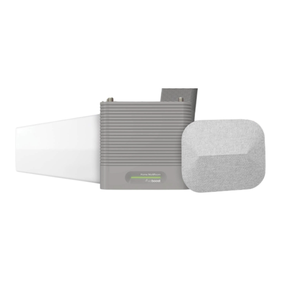
Package Contents Booster & Inside Antenna Outside Antenna Power Supply, Mounting & Mounting & Mounting Hardwire Power Bracket Bracket Bracket Supply & In-line Fuse Holder 2 Qty . 15 ft . (4 .5 m), Telescoping Pole, Wall 1 Qty . 30 ft . (9 m), Mount Brackets &... -
Page 4: Step 1 Mount Outside Antenna To Telescoping Pole
STEP 1 Mount Outside Antenna to Telescoping Pole Outside Antenna Mounting Bracket Mount outside antenna to telescoping pole with mounting bracket . Connect the 30 foot (9 meters) coax cable to outside antenna . Telescoping Pole coax cable connect STEP 2 Mount Telescoping recommended Pole to Side of RV placement... - Page 5 (STEP 2 cont .) upper Pole Foot Twist each Attach both wall mounts to the pole upper section feet located on the pole and fully counter-clockwise, extend, and then extend the pole . turn clockwise to lock into place. Insert the attached pin into the hole on Pole Foot Wall Mount the lower bracket to secure wall mount .
- Page 6 (STEP 2 cont .) remove adhesive backer Clean surface of RV where wall mounts will attach and remove the adhesive attach to side backer on both the upper and lower of RV wall mounts . NOTE: The wall mounts must be attached for the first-time setup of the Destination RV .
-
Page 7: Step 3 Mount Booster And Route Cable
STEP 3 Mount Booster and cabinet Route Cable Booster Find a location to place the booster inside the RV. A cabinet near a power source would be best . Be sure it’s in a location that the 9 meter outside Bracket antenna coax cable can reach . -
Page 8: Step 4 Mount Inside Antenna
STEP 4 Mount Inside Antenna Mount inside antenna using the 3M Inside Antenna Command™ Strips and connect coax cable. Be sure to have at least 20 feet (6 meters) vertical distance between the antennas . Then, check that the antennas point away from each other . -
Page 9: Step 5 Connect Coax Cables To Booster
STEP 5 Connect Coax Cables cable from Inside Antenna cable from to Booster Outside Antenna Connect the cable from the outside antenna to the port labeled “Outside Antenna” on the booster and connect the cable from the inside antenna to the port labeled “Inside Antenna”... -
Page 10: Booster Light Patterns
Booster Light Patterns SOLID GREEN This indicates that the booster is functioning properly, and there are no issues with installation . SOLID RED Band has shutoff . This is due to a feedback loop condition called oscillation . This is a built-in safety feature that causes a band to shut off to prevent harmful interference with a nearby cell tower . - Page 11 (Booster Light Patterns cont .) no further adjustments are necessary . If you are not experiencing the desired boost in coverage, then refer to Troubleshooting . SOLID YELLOW Band has shutoff due to overload from nearby cell tower . Outside antenna must be adjusted .
-
Page 12: Troubleshooting
Troubleshooting FIXING ANY RED LIGHT ISSUES This involves Solid Red & Blinking Green/Red lights. ■ Verify outside and inside antenna face away from each other . Unplug and replug in power supply . ■ Verify the inside antenna is at least 18 inches (45 centimeters) from the booster and pointed away from the booster . - Page 13 . The best way to keep these spheres of signal from overlapping is to maximize separation distance between the inside and outside antennas . 1 .866 .294 . 1 660 www .weboost .com or www .weboost .ca support@weboost .com ENGLISH...
- Page 14 Safety Guidelines Use only the power supply provided in this package . Use of a non-weBoost product may damage your equipment . Connecting this signal booster directly to the cell phone with use of an adapter will damage the cell phone .
- Page 15 (Safety Guidelines cont .) FOR MORE INFORMATION ON REQUIREMENTS SET OUT IN ISED CPC-2-1-05, SEE BELOW: http://www .ic .gc .ca/eic/site/smt-gst .nsf/eng/sf08942 .html FOR MORE INFORMATION ON REGISTERING YOUR SIGNAL BOOSTER WITH YOUR WIRELESS PROVIDER, PLEASE SEE BELOW: T-Mobile/Sprint/MetroPCS: https://www . t -mobile .com/support/coverage/register-a-signal-booster Verizon Wireless: https://www .
- Page 16 The following accessories are certified by the FCC to be used with the Destination RV . This radio transmitter 4726A-460059 has been approved by Innovation, Science and Economic Development Canada to operate with the antenna types listed below, with the maximum permissible gain indicated . Antenna types not included in this list that have a gain greater than the maximum gain indicated for any type listed are strictly prohibited for use with this device .
- Page 17 (Antenna Info cont .) FIXED OUTSIDE ANTENNA KIT OPTIONS Kit # Coax Type Antenna Type Ω Ln(ft) / Ln(m) 314445 RG-6 30 / 9 Directional 314475 RG-6 Directional 30 / 9 304423 RG-6 30 / 9 Omni 304421 RG-6 30 / 9 Omni ENGLISH...
- Page 18 Innovation, Science and Economic Development Canada’s licence-exempt RSS(s). Operation is subject to two conditions: (1) This device may not cause harmful interference, and (2) this device must accept any interference received, including interference that may cause undesired operation. Changes or modifications not expressly approved by weBoost could void the authority to operate this equipment. ENGLISH...
- Page 19 Returned Material Authorization (RMA) number supplied by weBoost . weBoost shall, at its option, either repair or replace the product . This warranty does not apply to any Signal Boosters determined by weBoost to have been subjected to misuse, abuse, neglect, or mishandling that alters or damages physical or electronic properties .
- Page 20 .weboost .com or www .weboost .ca support@weboost .com Copyright © 2021 weBoost . All rights reserved . Wilson Electronics products covered by U .S . patent(s) and pending application(s) For patents go to: weboost .com/us/patents NOT AFFILIATED WITH WILSON ANTENNA...
- Page 35 Mount Assembly (950630/YX030-15W) (971129) (850022) (900203) About Specifications The weBoost Destination RV is our most powerful cell signal MODEL NUMBER 470159* booster designed for large RVs, toy haulers, and trailers. FREQUENCIES Band 12/17 700 MHz For use only when parked, the booster stops dropped calls,...
- Page 36 Package Dimensions Support Combo Box: 9.125 in L x 9.125 in W x 76 in H 2-Year Warranty from Purchase. Website: http://support.weboost.com 9.125 in 9.125 in 9.125 in 9.125 in 9.125 in 9.125 in...
Need help?
Do you have a question about the 460059 and is the answer not in the manual?
Questions and answers