weBoost Destination RV (460059) Manual
- Installation manual (40 pages) ,
- Installation manual (60 pages)
Advertisement
Download the weBoost App
Use our app to guide you through setting up a weBoost cell phone signal booster in your home, business, or vehicle. Boost every network, including 5G, right away.


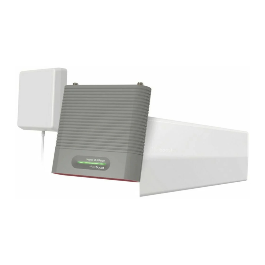
Package Contents

Installation Overview

 NOTE: Do not install pole on RV until stabilizer jacks and wheel chocks are in place and RV is immobilized.
STEP 1 Mount Outside Antenna to Telescoping Pole
Mount outside antenna to top section of telescoping pole with mounting bracket. Connect the 9 meter coax cable to outside antenna.

STEP 2 Prepare Telescoping Pole for Mounting
Extend the forth pole section to attach the top stabilizer.

NOTE: You may need to adjust the top latch with the included Allen wrench to get a secure fit.
DO NOT adjust the lower screw, as this may affect pole functionality.

Install the top stabilizer around the fourth section of telescoping pole by sliding both pieces together as shown.

Slide wall mount bracket onto the top stabilizer.

Slide on the other wall mount bracket onto the bottom stabilizer and use pin to lock in place.

Position the pole stabilizers so there is at Bracket least 1.2 meters of separation between them. This distance helps to stabilize the pole when mounted.

STEP 3 Mount Telescoping Pole to Side of RV
Find a location to install the pole. We recommend mounting near slide-out or toy hauler ramp door on the side.
Clean surface where the stabilizer mounts will attach.
Before fully securing the mounting brackets to RV, use the signal compass from within the weBoost app and point outside antenna toward the nearest cell tower in that area.

Fully extend pole and slide on pole foot at the bottom of pole. Remove the adhesive backer on both the top and bottom wall mount brackets.

Pole foot is intended for permanent attachment and should not be removed after installation.

Check for powerlines and avoid any overhead obstructions before remove adhesive securing pole to RV.

With firm pressure, apply the top stabilizer to the RV first, then press the bottom stabilizer in place.

When the pole is mounted, RV should not be in motion. Pole should be taken down prior to any of the following conditions:
- Moving RV
- Winds reaching over 35 mph
- Lightning occurrences
STEP 4 Mount Booster & Route Cable into RV
Find a location to place the booster inside the RV. A cabinet near a power source would be best. Be sure it can be reached by the 9 meter coax cable from the outside antenna. Use 3M Command™ Strips to secure mounting bracket into place and mount booster by sliding onto bracket.

Route the outside antenna cable into the RV. We recommend routing the cable through the slide-out gasket or through the back door of a toy hauler (flat entry cable included).

Do not fully extend the slide out until the cable is routed all the way through.
STEP 5 Mount Inside Antenna
Mount inside antenna with mounting bracket and 3M Command™ Strips. Connect the 5 meter coax cable to inside antenna.

Be sure to have at least 6 meter vertical distance between the antennas. Then, check that the antennas point away from each other. See installation overview.
STEP 6 Connect Coax Cables to Booster
Connect the cable from the outside antenna to the port labeled "Outside Antenna" on the booster and connect the cable from the inside antenna to the port labeled "Inside Antenna" on the booster.

STEP 7 Connect Power Supply to Booster
Connect AC power supply to the power jack at the bottom of the booster labeled " ". Plug the power supply into a power outlet in the RV.

Hardwiring to Power Option
This kit includes a Hardwire power option. Hardwire instructions are below. Use the steps below as a general template for wiring the power. There are multiple options for wiring and steps will vary depending on the vehicle type.
- Locate the vehicle fuse box. The fuse box location will vary by vehicle, refer to the vehicle's owner's manual.
- Route the power cable from the booster to the fuse box.
- Determine which fuse to hardwire the power to. Find an open fuse slot that is ignitionswitched, if there are no open fuse slots tied to the vehicle ignition power can be attached to an existing fuse. Wiring to an ignition-switched fuse will ensure the booster is not drawing power when the vehicle is off. Refer to the vehicle owner's manual for information about the fuses.
![information]() Note: You can use a circuit tester to test if the fuse is constant or ignition-switched. A constant fuse will stay on when the vehicle is off, and an ignition-switched fuse will have power when the vehicle is on but no power when it is off.
Note: You can use a circuit tester to test if the fuse is constant or ignition-switched. A constant fuse will stay on when the vehicle is off, and an ignition-switched fuse will have power when the vehicle is on but no power when it is off. - Connect the power supply. Once you have determined a fuse slot to use connect the positive lead on the power cable to the included in-line fuse then attach to a fuse tap and crimp into place (fuse tap is not included in the kit and will vary by vehicle type). Connect the fuse tap to the fuse slot you have chosen.
![information]() Note: You will need to determine which type of fuse tap is needed to complete the power wiring. Variations include ATO, Mini, Low Profile and Micro2. Consult the vehicle owner's manual to determine which fuse is needed for your installation.
Note: You will need to determine which type of fuse tap is needed to complete the power wiring. Variations include ATO, Mini, Low Profile and Micro2. Consult the vehicle owner's manual to determine which fuse is needed for your installation. - Ground the power supply. Most vehicle will have a factory grounding point. Slip the power supply's negative lead (black) under the metal bolt on the grounding point and tighten into place.
- Test the booster power. With the power supply hardwiring completed and inside and outside antennas in place attach the power supply to the booster. Turn the vehicle ignition on and make sure the booster power light turns on. Then turn the ignition off to make sure the booster powers off.
Booster Light Patterns
SOLID GREEN
This indicates that your Drive Reach booster is functioning properly and there are no issues with installation.
SOLID RED
Band has shutoff. This is due to a feedback loop condition called oscillation. This is a built in safety feature that causes a band to shut off to prevent harmful interference with a nearby cell tower. Refer to Troubleshooting section.
BLINKING RED, THEN SOLID GREEN
This indicates that one or more of the booster bands has reduced power due to a minor feedback loop condition called oscillation. This is a built in safety feature to prevent harmful interference with a nearby cell tower. If you are already experiencing the desired signal boost, then no further adjustments are necessary. If you are not experiencing the desired boost in coverage then refer to the Troubleshooting section.
LIGHT OFF
If the Drive Reach signal booster's light is off, verify your power supply has power.
NOTE: The signal booster can be reset by disconnecting and reconnecting the power supply.
After troubleshooting, you must initiate a new power cycle by disconnecting and then reconnecting power to the booster.
Troubleshooting
FIXING BLINKING OR RED LIGHT ISSUES
This section is only applicable if the light on the booster is red or blinking red and you are not experiencing the desired signal boost.
- Unplug the booster's power supply.
- Relocate the inside and outside antenna further from each other. The objective is to increase the separation distance between them, so that they will not create this feedback condition discussed before.
- Plug power supply back in and ensure switch is in ON position.
- Monitor the indicator light on your booster. If, after a few seconds of 'power on', a solid or blinking red light appears, repeat steps 1 through 3. Increase the separation distance until the condition is corrected and/or desired coverage area is achieved. Note: Horizontal separation of the two antennas typically requires a shorter separation distance than vertical separation.
If you are having any difficulties while testing or installing your booster, contact our weBoost Customer Support team for assistance (1-866-294-1660).
FREQUENTLY ASKED QUESTIONS
How can I contact customer support?
Customer Support can be reached Monday through Friday by calling 1-866-294-1660, or through our support site at support.weboost.com.
Why do I need to create distance between the outside antenna and inside antenna?
Antennas connected to a booster create spheres of signal. When these spheres overlap, a condition called oscillation occurs. Oscillation can be thought of as noise, which causes the booster to scale down its power or shut down to prevent damage. The best way to keep these spheres of signal from overlapping is to maximize separation between the inside and outside antennas.
1-866-294-1660
www.weboost.com
support@weboost.com
Safety Guidelines
Use only the power supply provided in this package. Use of a non-weBoost product may damage your equipment.
Connecting this signal booster directly to the cell phone with use of an adapter will damage the cell phone.
RF Safety Warning: Any antenna used with this device must be located at least 20 cm (8 inches) from all persons.
 AWS Warning: The Outside Antenna must be installed no higher than 10 meters (31 feet 9 inches) above ground.
This is a CONSUMER device.
BEFORE USE, you MUST REGISTER THIS DEVICE with your wireless provider and have your provider's consent. Most wireless providers consent to the use of signal boosters. Some providers may not consent to the use of this device on their network. If you are unsure, contact your provider.
In Canada, BEFORE USE you must meet all requirements set out in ISED CPC-2-1-05.
You MUST operate this device with approved antennas and cables as specified by the manufacturer. Antennas MUST be installed at least 20 cm (8 inches) from (i.e., MUST NOT be installed within 20 cm of) any person.
You MUST cease operating this device immediately if requested by the FCC (or ISED in Canada) or licensed wireless service provider.
E911 location information may not be provided or may be inaccurate for calls served by using this device.
FOR MORE INFORMATION ON REGISTERING YOUR SIGNAL BOOSTER WITH YOUR WIRELESS PROVIDER IN THE U.S., PLEASE GO TO THE LINK BELOW:
https://www.weboost.com/carrier-registration
Antenna Info
The following accessories are certified by the FCC to be used with the Destination RV.
| BAND 12/17 | BAND 13 | BAND 5 | BAND 4 | BAND 25/2 | |
| Outside antenna maximum permissible antenna gain (dBi) 50Ω | 4.9 | 4.9 | 4.5 | 4.6 | 4.2 |
| Inside antenna maximum permissible antenna gain (dBi) 50Ω | 3.2 | 3.2 | 3.2 | 2.6 | 2.7 |
This radio transmitter 4726A-460059 has been approved by Innovation, Science and Economic Development Canada to operate with the antenna types listed below, with the maximum gain indicated. Antenna types not included in this list that have a gain greater than the maximum gain indicated for any type listed are strictly prohibited for use with this device.
| FIXED INSIDE ANTENNA KIT OPTIONS | |||||||||
| Kit # | Coax Type | Ln(m) | Antenna Type | Ω | |||||
| 301211 | RG-6 | 9 | Desktop | 75 | |||||
| 304419 | RG-6 | 9 | Dome | 75 | |||||
| 311239 | RG-6 | 9 | Panel | 75 | |||||
| FIXED OUTSIDE ANTENNA KIT OPTIONS | |||||||||
| Kit # | Coax Type | Ln(m) | Antenna Type | Ω | |||||
| 314445 | RG-6 | 9 | Directional | 75 | |||||
| 314475 | RG-6 | 9 | Directional | 75 | |||||
| 304423 | RG-6 | 9 | Omni | 75 | |||||
| 304421 | RG-6 | 9 | Omni | 75 | |||||
Specifications
| Drive Reach Cell Signal Booster | |||||
| Model | 460059 | ||||
| FCC | PWO460059 | ||||
| IC | 4726A-460059 | ||||
| Connectors | F-Female | ||||
| Antenna Impedance | 75 Ohms | ||||
| Frequency | 698-716 MHz, 729-746 MHz, 746-757 MHz, 776-787 MHz, 824-849 MHz, 869-894 MHz, 1710-1755 MHz, 1850-1915 MHz, 1930-1995 MHz, 2110-2155 MHz | ||||
| Power output for single cell phone (Uplink) dBm | 700 MHz B12/17 24.8 | 700 MHz B13 25.0 | 800 MHz B5 25.3 | 1700 MHz B4 25.2 | 1900 MHz B2 25.1 |
| Power output for single cell phone (Downlink) dBm | 12.7 | 12.2 | 12.8 | 12.6 | 12.8 |
| Noise Figure | 5 dB (nominal) | ||||
| Isolation | > 110 dB | ||||
| Power Requirements | 5 VDC | ||||
Each Signal Booster is individually tested and factory set to ensure FCC compliance. The Signal Booster cannot be adjusted without factory reprogramming or disabling the hardware. The Signal Booster will amplify, but not alter incoming and outgoing signals in order to increase coverage of authorized frequency bands only. If the Signal Booster is not in use for five minutes, it will reduce gain until a signal is detected. If a detected signal is too high in a frequency band, or if the Signal Booster detects an oscillation, the Signal Booster will automatically turn the power off on that band. For a detected oscillation the Signal Booster will automatically resume normal operation after a minimum of 1 minute. After 5 (five) such automatic restarts, any problematic bands are permanently shut off until the Signal Booster has been manually restarted by momentarily removing power from the Signal Booster. Noise power, gain, and linearity are maintained by the Signal Booster's microprocessor.
Documents / Resources
References
![www.apple.com]() App Store - Apple
App Store - Apple![play.google.com]() Google Play
Google PlayCell Phone Signal Boosters for Home, Cars, & More - weBoost
Carrier Registration - Register Your weBoost
Download manual
Here you can download full pdf version of manual, it may contain additional safety instructions, warranty information, FCC rules, etc.
Advertisement


Need help?
Do you have a question about the Destination RV and is the answer not in the manual?
Questions and answers