Advertisement
UWAGA! Aby uniknąć zagroŜenia dla zdrowia
i Ŝycia oraz uszkodzenia sprzętu, urządzenie powinno być instalowane
z zastosowaniem obowiązujących norm przez wykwalifikowany
personel. Przedstawiany tu produkt moŜe być w kaŜdej chwili
zmodyfikowany. Dane techniczne oraz część opisowa oddają w jak
najdokładniejszy sposób posiadaną przez nas wiedzę, jednak nie
bierzemy odpowiedzialności za ewentualne błędy, braki oraz sytuacje
awaryjne.
Wprowadzenie
To proste urządzenie posiada zrozumiały, przyjazny dla uŜytkownika panel
przedni, który ułatwia korzystanie z niego nawet niezbyt biegłym
uŜytkownikom. WyposaŜony jest równieŜ w szeroki zakres funkcji
kontrolnych, normalnie stosowanych w urządzeniach o wyŜszym
standardzie.
Opis
• Sterowanie generatorem z funkcją automatycznego wykrywania błędu
sieci (AMF)
• Wejście pomiarowe sieci trójfazowej (L1-L2/N-L3)
• Wejście pomiarowe jednofazowe generatora (L1-L2/N)
• Uniwersalne zasilanie 12-24Vdc
• 1 wyświetlacz alfanumeryczny LED, 4 literowy
• 16 diód LED do wiuzualizacji statusu i pomiarów
• 6 przyciskowa klawiatura
• Port RS-232 do ustawiania
• 4 programowalne wejścia cyfrowe
• 5 programowalnych wyjść przekaźnikowych
Klawiatura
Przyciski OFF/RESET, AUT i TEST – Wciśnij te przyciski by wybrać tryb
pracy. Świecąca dioda LED wskaŜe wybrany tryb pracy; jeśli miga oznacza
to iŜ aktywne jest ustawianie przez RS232.
Przyciski MAINS i GEN – Działają tylko w trybie TEST, słuŜą do
przełączania obciąŜenia z sieci do generatora i odwrotnie. Świecąca dioda
LED przy symbolach sieci i generatora wskazuje czy odpowiednie,
ustawione napięcia są w zakresie limitów. Śiecąca dioda LED przy
urządzeniu przełączającym oznacza aktywacje urządzeń przełączających.
Przycisk
– SłuŜy do wyboru wyświetlanego pomiaru.
Tryb pracy
Tryb OFF/RESET – Silnik nie moŜe pracować. Jeśli sieć jest obecna,
obciąŜenie jest podłączone do sieci. Zmiana do trybu OFF/RESET
powoduje natychmiastowe zatrzymanie silnika, jeśli pracuje, a ewentualne
alarmy są kasowane. W przypadku kiedy obecny jest nadal jakiś alarm, nie
moŜe on zostać skasowany.
Tryb TEST – Rozruch silnika i przełączanie obciąŜenia z sieci do
generatora i odwrotnie nie mogą być przeprowadzone przy uŜyciu
przycisków MAINS i GEN. Zatrzymanie silnika odbywa się przy uŜyciu
przycisku OFF/RESET
Tryb AUT – W przypadku kiedy sieć nie jest obecna (poza ustalonymi
limitami), silnik automatycznie startuje, lub zatrzymuje się kiedy sieć
"powraca".
Alarmy
Kiedy pojawia się stan alarmu, na wyświetlaczu pokazuje się kod
identyfikujący, następnie po 2 sekundach wyświetlany jest opis alarmu
(przez przewijanie tekstu na wyświetlaczu).
Alarm moŜe być skasowany przez wciśniecie przycisku OFF/RESET
co zapobiega niezamierzonemu uruchomieniu silnika. Jeśli nie moŜna
skasować alarmu, oznacza to, iŜ przyczyna alarmu nadal istnieje.
Doc: MHPL_GB201A0206.doc
PL
RGAM 10
Sterownik generatora
z funkcją AMF
(Automatyczne wykrywanie
błędu sieci)
INSTRUKCJA UśYTKOWNIKA
RGAM 10
Gen-set controller
with AMF function
(Automatic Mains Failure)
INSTRUCTIONS MANUAL
WARNING! This equipment is to be installed by qualified personnel,
complying to current standards, to avoid damages or safety hazards.
Products illustrated herein are subject to alteration and changes without
prior notice. Technical data and descriptions in the documentation are
accurate, to the best of our knowledge, but no liabilities for errors,
omissions or contingencies arising therefrom are accepted
Introduction
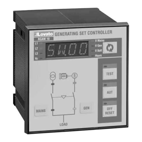
This simple, streamlined device features a clear, user-friendly front panel
that facilitates use also by less expert users. It is also equipped with a
wide range of control functions usually found only on higher range
appliances.
Description
• Gen-set control with automatic supervision of the AMF (Automatic
Mains Failure) function
• Three-phase mains measurement input (L1-L2/N-L3)
• Single-phase gen-set measurement input (L1-L2/N)
• 12-24VDC universal power supply unit
• 1 alphanumeric LED display with 4 characters
• 16 LEDs for status and measurement display
• 6-key membrane keyboard
• RS232 communication interface for set-up.
• 4 programmable digital inputs
• 5 programmable relay outputs
Front key function
OFF/RESET, AUT and TEST keys – Press these keys to select the
operating mode. The illuminated LED indicates the selected operating
mode; if it is flashing, set-up via RS232 is active.
MAINS and GEN keys – They work in TEST operating mode only, used
to switch the load from mains to generator and vice versa. The
illuminated LEDs of the mains and generator symbols indicate the
respective voltages are within preset limits. The illuminated LEDs next to
the changeover symbols indicate the activation of switching devices.
key – Used to select the measurement to display.
Operating mode
OFF/RESET mode – The engine cannot operate. If the mains is present,
the load is switched to mains. Changing to OFF/RESET mode and if the
engine is running, the engine is immediately stopped and eventual
alarms are reset. If the cause of an alarm is still present, it cannot be
reset.
TEST mode – The engine starts and load switching from mains to the
generator or vice versa can be done using the MAINS and GEN keys.
Engine stopping can be done using the OFF/RESET key.
AUT mode – In case of mains not present (out of the preset limits), the
engine automatically starts, or stops when the mains returns.
Alarms
When an alarm occurs, the display views an identification code; after 2
seconds, the description of the alarm is displayed in scrolling text.
Alarm conditions can be reset by pushing the OFF/RESET key and any
unintentional engine starting is prevented.
If the alarm does not reset, this means the alarm conditions are still
present.
13/02/2007
.
p. 1 / 12
Advertisement
Table of Contents

Subscribe to Our Youtube Channel
Related Manuals for LOVATO ELECTRIC RGAM 10


Summary of Contents for LOVATO ELECTRIC RGAM 10
- Page 1 RGAM 10 RGAM 10 Sterownik generatora Gen-set controller z funkcją AMF with AMF function (Automatyczne wykrywanie (Automatic Mains Failure) błędu sieci) INSTRUKCJA UśYTKOWNIKA INSTRUCTIONS MANUAL UWAGA! Aby uniknąć zagroŜenia dla zdrowia WARNING! This equipment is to be installed by qualified personnel, i Ŝycia oraz uszkodzenia sprzętu, urządzenie powinno być...
-
Page 2: Menu Komend
Zasilanie Power-up Przy zaniku napięcia, sterownik automatycznie przechodzi w tryb At power-up, the controller automatically sets to OFF/RESET mode. If OFF/RESET. Jeśli wymagane jest by sterownik RGAM10, po ponownym one needs the RGAM10 set to the same mode before it was powered zasileniu, ustawiony był... - Page 3 Ustawienia przez PC Set-up by means of PC Ustawień moŜna dokonać w bardzo prosty sposób przez podłączenie The set-up can be more easily done via PC connected to the controller do portu RS232 komputera osobistego. Przy uŜyciu oprogramowania, RS232 port. Using the set-up software, it is possible to transfer moŜliwy jest transfer parametrów (wcześniej ustawionych) ze sterownika parameters (previously set) from the controller to the PC and vice versa.
- Page 4 P0413 czas zalewania (s) OFF/1-60 P0413 Priming time (s) OFF/1-60 P0414 czas dławienia zaworu (s) OFF/1-60 P0414 Choke valve time (s) OFF/1-60 P0415 limit OFF cewki dławikowej (%) 3-100 P0415 Choke OFF limit (%) 3-100 P0416 liczba rozruchów przeprowadzanych 1-10 P0416 Number of starting attempts with choke 1-10 z dławieniem...
- Page 5 P0606 MIN/MAX limit histerezy (%) 0.0-5.0 P0606 MIN/MAX hysteresis limit (%) 0.0-5.0 P0607 MAX limit asymetrii (%) OFF / 5-25 P0607 MAX asymmetry limit (%) OFF / 5-25 P0608 opóźnienie MAX asymetrii (s) 0-600 P0608 MAX asymmetry delay (s) 0-600 P0609 MAX limit częstotliwości (%) 100-120/OFF P0609 MAX frequency limit (%)
- Page 6 MENU 08 – NIEDOSTĘPNE MENU 08 – NOT AVAILABLE MENU 09 – NIEDOSTĘPNE MENU 09 – NOT AVAILABLE MENU 10 – NIEDOSTĘPNE MENU 10 – NOT AVAILABLE MENU 11 – RÓśNE Domyślny Zakres MENU 11 – MISCELLANEOUS Default Range P1101 Wybór trybu NOR/EJP/ P1101 Mode selection NOR/EJP/...
- Page 7 termicznego equipment Zewnętrzne przełączanie W trybie AUT, wykonuje przełączanie E.CHO External Changeover In AUT mode, performs switching between E.CHO pomiędzy siecią a generatorem mains and generator Blokada klawiatury Blokuje klawiaturę K.LOC Keyboard Lock Blocks the keyboard K.LOC MENU 13 – WYJŚCIA PROGRAMOW. Domyślny Zakres MENU 13 –...
- Page 8 Niespodziewane zatrzymanie Unexpected stop Awaria zatrzymania Stop failure Niska częstotliwość generatora Low generator frequency Wysoka częstotliwość generatora High generator frequency Niskie napięcie generatora Low generator voltage Wysokie napięcie generatora High generator voltage Zadziałanie zewnętrznej ochrony generatora External generator protection trip Niewłaściwa kolejność...
- Page 9 Ustawienia alarmów (wartości domyślne) Alarms setting (default values) Wysoka temperatura High temperature Niskie ciśnienie oleju Low oil pressure Błąd czujnika ciśnienia oleju Oil pressure sensor fault Niski poziom paliwa Low fuel level Wysokie napięcie baterii High battery voltage Niskie napięcie baterii Low battery voltage Bateria rozładowana Inefficient battery...
-
Page 10: Technical Characteristics
Charakterystyka techniczna Technical characteristics Zasilanie pomocnicze Auxiliary power supply Znamionowe napięcie baterii 12 lub 24VDC (obojętnie) Battery rated voltage 12 or 24VDC indifferently Maksymalny pobór prądu 230mA przy12VDC i 120mA przy Maximum current consumption 230mA at 12VDC e 120mA at 24VDC 24VDC Maksymalny pobór/rozproszenie mocy 2,8W... -
Page 11: Schematy Połączeń
Masa 470g Weight 470g Normy i uznania Reference standards IEC/EN 61010-1, IEC/EN 55011, EN 50082-2, IEC/EN 60028-2-61, IEC/EN 61010-1, IEC/EN 55011, EN 50082-2, IEC/EN 60028-2-61, IEC/EN 60068-2-6 (LROS-Lloyd’s Register Of Shipping), IEC/EN 60068-2-52 IEC/EN 60068-2-6 (LROS-Lloyd’s Register Of Shipping), IEC/EN 60068-2-52 (RINA- (RINA-Italian Naval Register), UL 508 and CSA C22.2_N°14-95 (cULus). - Page 12 Schemat dla podłączenia jednofazowego Schemat połączeń generatora z magnetoelektryczną ładowarką alternatorową Wiring for single-phase generating set Wiring for generating set with permanent magnet battery charger alternator C.B. REG. Podłączenie zacisków (widok od tyłu) Terminal block connections (rear view) MAI NS GENERATOR - Nie używane - Not used...
Need help?
Do you have a question about the RGAM 10 and is the answer not in the manual?
Questions and answers