Table of Contents
Advertisement
Quick Links
LOVATO ELECTRIC S.P.A.
24020 GORLE (BERGAMO) ITALIA
VIA DON E. MAZZA, 12
TEL. 035 4282111
FAX (Nazionale): 035 4282200
FAX (International): +39 035 4282400
L
E
E-mail info@
ovato
lectric.com
L
E
Web
www.
ovato
lectric.com
WARNING!
– Carefully read the manual before the installation or use.
– This equipment is to be installed by qualified personnel, complying to current standards, to avoid
damages or safety hazards.
– Before any maintenance operation on the device, remove all the voltages from measuring and supply inputs and short-
circuit the CT input terminals.
– The manufacturer cannot be held responsible for electrical safety in case of improper use of the equipment.
– Products illustrated herein are subject to alteration and changes without prior notice. Technical data and descriptions
in the documentation are accurate, to the best of our knowledge, but no liabilities for errors, omissions or
contingencies arising there from are accepted.
– A circuit breaker must be included in the electrical installation of the building. It must be installed close by the
equipment and within easy reach of the operator. It must be marked as the disconnecting device of the equipment:
IEC /EN 61010-1 § 6.11.3.1.
– Clean the device with a soft dry cloth; do not use abrasives, liquid detergents or solvents.
ATTENTION !
– Lire attentivement le manuel avant toute utilisation et installation.
– Ces appareils doivent être installés par un personnel qualifié, conformément aux normes en vigueur en
matière d'installations, afin d'éviter de causer des dommages à des personnes ou choses.
– Avant toute intervention sur l'instrument, mettre les entrées de mesure et d'alimentation hors tension et court-circuiter
les transformateurs de courant.
– Le constructeur n'assume aucune responsabilité quant à la sécurité électrique en cas d'utilisation impropre du
dispositif.
– Les produits décrits dans ce document sont susceptibles d'évoluer ou de subir des modifications à n'importe quel
moment. Les descriptions et caractéristiques techniques du catalogue ne peuvent donc avoir aucune valeur
contractuelle.
– Un interrupteur ou disjoncteur doit être inclus dans l'installation électrique du bâtiment. Celui-ci doit se trouver tout
près de l'appareil et l'opérateur doit pouvoir y accéder facilement. Il doit être marqué comme le dispositif
d'interruption de l'appareil : IEC/ EN 61010-1 § 6.11.3.1.
– Nettoyer l'appareil avec un chiffon doux, ne pas utiliser de produits abrasifs, détergents liquides ou solvants.
ACHTUNG!
– Dieses Handbuch vor Gebrauch und Installation aufmerksam lesen.
– Zur Vermeidung von Personen- und Sachschäden dürfen diese Geräte nur von qualifiziertem
Fachpersonal und unter Befolgung der einschlägigen Vorschriften installiert werden.
– Vor jedem Eingriff am Instrument die Spannungszufuhr zu den Messeingängen trennen und die Stromwandler
kurzschlie en.
– Bei zweckwidrigem Gebrauch der Vorrichtung übernimmt der Hersteller keine Haftung für die elektrische Sicherheit.
– Die in dieser Broschüre beschriebenen Produkte können jederzeit weiterentwickelt und geändert werden. Die im
Katalog enthaltenen Beschreibungen und Daten sind daher unverbindlich und ohne Gewähr.
– In die elektrische Anlage des Gebäudes ist ein Ausschalter oder Trennschalter einzubauen. Dieser muss sich in
unmittelbarer Nähe des Geräts befinden und vom Bediener leicht zugänglich sein. Er muss als Trennvorrichtung für das
Gerät gekennzeichnet sein: IEC/ EN 61010-1 § 6.11.3.1.
– Das Gerät mit einem weichen Tuch reinigen, keine Scheuermittel, Flüssigreiniger oder Lösungsmittel verwenden.
ADVERTENCIA
– Leer atentamente el manual antes de instalar y utilizar el regulador.
– Este dispositivo debe ser instalado por personal cualificado conforme a la normativa de instalación
vigente a fin de evitar daños personales o materiales.
– Antes de realizar cualquier operación en el dispositivo, desconectar la corriente de las entradas de alimentación y
medida, y cortocircuitar los transformadores de corriente.
– El fabricante no se responsabilizará de la seguridad eléctrica en caso de que el dispositivo no se utilice de forma
adecuada.
– Los productos descritos en este documento se pueden actualizar o modificar en cualquier momento. Por consiguiente,
las descripciones y los datos técnicos aquí contenidos no tienen valor contractual.
– La instalación eléctrica del edificio debe disponer de un interruptor o disyuntor. Éste debe encontrarse cerca del
dispositivo, en un lugar al que el usuario pueda acceder con facilidad. Además, debe llevar el mismo marcado que el
interruptor del dispositivo (IEC/ EN 61010-1 § 6.11.3.1).
– Limpiar el dispositivo con un trapo suave; no utilizar productos abrasivos, detergentes líquidos ni disolventes.
UPOZORNĚNÍ
AVERTIZARE!
GB
GENERATING SET CONTROLLER
Instructions manual
RGK750
ATTENZIONE!
– Leggere attentamente il manuale prima dell'utilizzo e l'installazione.
– Questi apparecchi devono essere installati da personale qualificato, nel rispetto delle vigenti normative
impiantistiche, allo scopo di evitare danni a persone o cose.
– Prima di qualsiasi intervento sullo strumento, togliere tensione dagli ingressi di misura e di alimentazione e
cortocircuitare i trasformatori di corrente.
– Il costruttore non si assume responsabilità in merito alla sicurezza elettrica in caso di utilizzo improprio del dispositivo.
– I prodotti descritti in questo documento sono suscettibili in qualsiasi momento di evoluzioni o di modifiche. Le
descrizioni ed i dati a catalogo non possono pertanto avere alcun valore contrattuale.
– Un interruttore o disgiuntore va compreso nell'impianto elettrico dell'edificio. Esso deve trovarsi in stretta vicinanza
dell'apparecchio ed essere facilmente raggiungibile da parte dell'operatore. Deve essere marchiato come il dispositivo
di interruzione dell'apparecchio: IEC/ EN 61010-1 § 6.11.3.1.
– Pulire l'apparecchio con panno morbido, non usare prodotti abrasivi, detergenti liquidi o solventi.
UWAGA!
ПРЕДУПРЕЖДЕНИЕ!
DİKKAT!
G
B
1
Advertisement
Table of Contents

Subscribe to Our Youtube Channel
Related Manuals for LOVATO ELECTRIC RGK750


Summary of Contents for LOVATO ELECTRIC RGK750
- Page 1 GENERATING SET CONTROLLER Instructions manual LOVATO ELECTRIC S.P.A. 24020 GORLE (BERGAMO) ITALIA VIA DON E. MAZZA, 12 TEL. 035 4282111 FAX (Nazionale): 035 4282200 FAX (International): +39 035 4282400 RGK750 E-mail info@ ovato lectric.com www. ovato lectric.com WARNING! ATTENZIONE! – Carefully read the manual before the installation or use.
-
Page 2: Table Of Contents
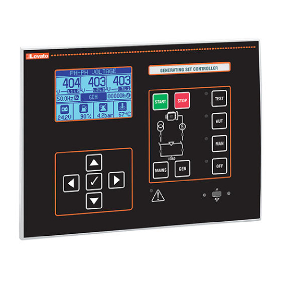
The RGK750 controller unit has been designed to offer state-of-the-art functions for generating set (genset) applications, both with and without automatic mains outage control. Built with dedicated components and extremely compact, the RGK750 combines the modern design of the front panel with practical installation and rear expansion slotting for EXP series modules. The LCD screen provides a clear and intuitive user interface. -
Page 3: Keyboard Functions
OPERATING MODES OFF mode - The engine will not be started. If running, the engine will stop immediately when this mode is selected. The mains contactor is closed. This mode reproduces the status of the RGK750 when it is not powered. -
Page 4: Main Menu
MAIN MENU – The main menu is made up of a group of graphic icons (shortcuts) that allow rapid access to measurements and settings. – Starting from normal viewing, press ✔ key. The main menu screen is displayed. – Press s t to rotate clockwise/counter clockwise to select the required function. The selected icon is highlighted and the central part of the display shows the description of the function. –... -
Page 5: Table Of Display Pages
TABLE OF DISPLAY PAGES PAGES EXAMPLE Line-to-line voltages Phase voltages Current … L-L voltages THD L-N voltages THD Currents THD Resistive sensors programmed as digital input L-L Voltages/Currents L-N Voltages/Currents Current asymmetry Active power Reactive power Apparent power Power factor Energy meters Summary of electrical measurements Engine speed... - Page 6 PAGES EXAMPLE Fuel level status Fuel autonomy Generator thermal protection Engine hour and work counters Maintenance intervals Rent List of events Alternative configurations...
-
Page 7: Harmonic Analysis Page
Note: Some of the pages listed above may not be displayed if the relevant function is disabled. For example, if the rent function is not programmed, the corresponding page will not be shown. HARMONIC ANALYSIS PAGE – In the RGK750, it is possible to enable the calculation of the FFT harmonic analysis up to the 31st order of the following measurements: • Phase-to-phase voltages •... -
Page 8: Waveform
– The user can create a maximum of 4 customised display pages. – Each of these pages can view 3 measurements, freely chosen among the available readings of the RGK750. – The title of the page can be freely programmed by the user. -
Page 9: Additional Resources
– The two channels can communicate at the same time. – Activating the Gateway function it is possible to use a RGK750 with both an Ethernet port and a RS485 port, that acts as a gateway over other RGKs equipped with RS485 only, in order to achieve a more economical configuration (one Ethernet port only). -
Page 10: Can Bus
– You can enter all the variables managed by the RGK750 in the program logic, such as inputs (INPx), limit thresholds (LIMx), remote variables (REMx), and controller status (RALx), etc. – The results of processing the various branches of the ladder logic are saved in internal variables (PLCx) which can then be used to control the outputs of the RGK750, or as backup memories to build a more complex logic, or also to control user-defined alarms (UAx). -
Page 11: Supported Measurements
– In view of the many sensors connected to an ECU, a high number of possible codes is managed. -
Page 12: Mutual Stand-By Function
– Email sending As with SMS, but sent to an email account. – Receiving SMS commands Allows to control the RGK750 by sending an SMS. The supported commands, which can be concatenated into a single message, are the following: COMMAND Action OFF, MAN, AUT, TEST Change operating mode according to the command. - Page 13 – Sending data and event files on remote FTP server All the events recorded by the RGK750 can be sent to a file managed by FTP server. In this way, the server has the updated history of what has happened on all gensets in the field.
- Page 14 – If the user does not press any key for more than 2 minutes, the system leaves the setup automatically and goes back to normal viewing without saving the changes done on parameters. – N.B.: A backup copy of the setup data (settings that can be modified using the keyboard) can be saved in the eeprom memory of the RGK750. This data can be restored when required in the work memory. The...
- Page 15 TABLE OF PARAMETERS M01 - UTILITY Default Range P01.01 Language English English Italiano Francais Espanol Russian P01.02 Set clock at power up OFF-ON P01.03 Power-up operating mode OFF mode OFF mode Previous P01.04 LCD contrast 0-100 P01.05 Display backlight high intensity 0-100 P01.06 Display backlight low intensity...
- Page 16 M04 – CONFIGURATIONS (CNFn, n=1…4) Default Range P04.n.01 Rated voltage 50-500000 P04.n.02 Type of connection L1-L2-L3-N L1-L2-L3-N L1-L2-L3 L1-N-L2 L1-N P04.n.03 Type of voltage control L-L + L-N P04.n.04 Rated current 1-10000 P04.n.05 Rated frequency P04.n.06 Rated engine rpm 1500 750-3600 P04.n.07 Rated active power Aut / 1-10000...
- Page 17 M07 – ENGINE SPEED Default Range P07.01 Engine speed reading source FREQ-GEN. LS Pick-up HS Pick-up P07.02 RPM/W - pick-up ratio 1.000 0.001-50.000 P07.03 MAX. speed limit 100-120 P07.04 MAX. speed alarm delay 0.5-60.0 P07.05 MIN. speed limit 80-100 P07.06 MIN.
- Page 18 M09 – COOLANT TEMPERATURE Default Range P09.01 Reading source P09.03 Type of resistive sensor VEGLIA DATCON CUSTOM …. P09.04 Resistive sensor offset -30.0 to +30.0 P09.05 Temperature unit of measurement °C °C °F P09.06 MAX. temperature prealarm ° 20-300 P09.07 MAX.
- Page 19 M11 – ENGINE STARTING Default Range P11.01 Engine started threshold via battery charger alternator voltage 10.0 OFF/3.0-30 P11.02 Engine started threshold via generator voltage OFF/10-100 P11.03 Engine started threshold via generator frequency OFF/10-100 P11.04 Engine started threshold via engine speed OFF/10-100 P11.05 Glow plugs preheating time...
- Page 20 P13.12 – Min. frequency trip delay. P13.13 – OFF = Mains control disabled. INT = Mains controlled by RGK750. EXT = Mains controlled by external device. A programmable input can be used with the External mains control function connected to the external mains control device.
- Page 21 P14.12 – Min. frequency trip delay. P14.13 – OFF = Generator control disabled. INT = Generator controlled by RGK750. EXT = Generator controlled by external device. A programmable input must be used with “External mains control” function connected to the external generator control device.
- Page 22 0.0-6000.0 Note: This menu is divided into 19 sections that refer to 19 possible digital inputs INP1…INP19, which can be managed by the RGK750; INP1..INP8 on the base device and INP9…INP16 on any installed expansion modules. Inputs 17-18-19 make reference to analog inputs FUEL, TEMP, PRESS and when these are set to OFF.
- Page 23 P19.n.03 Normal/reverse output NOR / REV Note: This menu is divided into 16 sections that refer to 16 possible digital outputs OUT1…OUT16, which can be managed by the RGK750; OUT1..OUT10 on the base device and OUT11…OUT16 on any installed expansion modules.
- Page 24 P21.01 – Selects the type of engine ECU. If the ECU you wish to use cannot be found in the list of possible choices, select “Generic J1939”. In this case, the RGK750 only analyses messages on the CAN that meet...
- Page 25 OUT = Communication through programmable output set as “Remote alarms” function, connected to the digital input of the RGKRR. CAN = The RGK750 and RGKRR communicate through the CAN interface. Unless there are indications to the contrary for a specific ECU, it is usually possible to communicate simultaneously with the RGKRR and the engine ECU on the same CAN line.
- Page 26 P25.n.01 – Signal that increments the count (on rising edge). This may be the power-up of the RGK750 (ON), when a threshold is exceeded (LIMx), an external input is enabled (INPx), or for a logic condition (PLCx), etc. P25.n.02 – Channel number x with reference to the previous parameter.
- Page 27 Note: This menu is divided into 6 sections, for the generation of energy consumption pulse variables PUL1…PUL6. P31.n.01 – Defines which energy source should generate pulsing for the 6 possible counters managed by the RGK750. kWh M = Mains active energy. kWh G = Generator active energy. kvarh M = Mains reactive energy. kvarh G = Generator reactive energy.
- Page 28 ALARM TABLE CODE DESCRIPTION DEFAULT ALARM PROPERTIES ● ● ● ● Engine temperature warning (analog sensor) ● ● ● ● ● ● ● High engine temperature (analog sensor) ● ● ● ● ● ● Analog temperature sensor fault ● ● ●...
-
Page 29: Alarm Properties
– If the alarm cannot be reset, the problem that generated the alarm must still be solved. – In the case of one or more alarms, the RGK750 operation depends on the property settings of the active alarms. ALARM PROPERTIES Various properties can be assigned to each alarm, including user alarms (User Alarms, UAx): –... - Page 30 See menu M17. Use the commands menu to reset the operating hours and the alarm after servicing. Maintenance request 2 Maintenance request 3 System error RGK750 internal error. See System errors chapter for possible solutions. Tank too empty The relevant programmable input signals tank too empty (default active open). Filling pump stopped.
-
Page 31: Input Function Table
Inhibits automatic switching back to the mains when its values are within the limits. MAINS contactor feedback Auxiliary contact of mains switchgear used to inform RGK750 of its actual status (feedback). Alarm A41 is generated in the case of incongruity between the command output and status. -
Page 32: Output Function Table
Start engine with compressed air, as an alternative/alternating with starter motor. See parameter P11.26. Operating mode Output energised when the RGK750 is in one of the modes set with parameter P23.13. Mains voltage state Energised when the mains voltage returns within the set limits. - Page 33 INSTALLATION – RGK750 is designed for flush-mount installation. With proper mounting, it guarantees IP65 front protection. – Insert the controller into the panel cutout. Making sure that the gasket is properly positioned between the panel and the controller front frame.
- Page 34 ∂ Reference earth/ground for analog sensors to be connected directly on the engine block. CANBUS CONNECTION The CANbus connection has two 120-Ohm termination resistors at both ends of the bus. To connect the resistor incorporated in the RGK750 board, jumper TR and CAN-L. WIRING FOR SINGLE-PHASE GENERATING SET WIRING FOR TWO-PHASE GENERATING SET...
- Page 35 WIRING FOR GENERATING SET WITH PERMANENT MAGNET BATTERY CHARGER ALTERNATOR WIRING FOR GENERATING SET WITH MAGNETIC PICK-UP SPEED DETECTOR RA OUTPUT (OUT 7) USED AS RELAY DRIVER NPN output PNP output DC coil relay DC coil relay MAX 50mA MAX 50mA F0,1A F0,1A...
-
Page 36: Terminal Arrangement
TERMINALS ARRANGEMENT 23 24 25 26 MAINS CURRENT OUT 9 OUT 10 SLOT 1 SLOT 2 BATTERY 53 54 55 56 57 58 59 60 MECHANICAL DIMENSIONS AND CUTOUT [mm] 220.00 240.00 56.40 11.30 32.60... - Page 37 TECHNICAL CHARACTERISTICS SSR output OUT3 - OUT 6 (+ battery voltage output) Supply Battery rated voltage 12 or 24V= indifferently Type of output 4 x 1 NO + one common terminal Maximum current consumption 400mA at 12V= and 200mA at 24V= Rated voltage 12-24V= from battery Maximum power consumption/dissipation 4.8W...
Need help?
Do you have a question about the RGK750 and is the answer not in the manual?
Questions and answers