LOVATO ELECTRIC RGK600 Instruction Manual
Generating set controller
Hide thumbs
Also See for RGK600:
- Instruction manual (43 pages) ,
- Installation manual (12 pages) ,
- Installation manual (12 pages)
Table of Contents
Advertisement
Quick Links
UWAGA!
● Należy uważnie przeczytać instrukcję przed instalacją lub użytkowaniem.
● By uniknąć zniszczeń lub zagrożenia życia urządzenia powinny
być instalowane przez wykwalifikowany personel w zgodzie z obowiązującymi
standardami.
● Przed pracami serwisowymi, należy odłączyć wszystkie napięcia od wejść pomiarowych i zasilania
pomocniczego oraz zewrzeć zaciski przekładnika prądowego.
● Produkty zaprezentowane w poniższym dokumencie mogą zostać zmienione lub ulepszone bez konieczności
wcześniejszego informowania o tym.
● Dane techniczne oraz opisy oddają w jak najdokładniejszy sposób posiadaną przez nas wiedzę, jednak
nie bierzemy odpowiedzialności za ewentualne błędy, braki oraz sytuacje awaryjne.
● W układzie należy zamontować rozłącznik (wyłącznik), który musi znajdować się niedaleko urządzenia
i być łatwo dostępny dla operatora. Musi spełniać wymogi następujących norm: IEC/ EN 61010-1 § 6.12.2.1.
● Należy czyścić urządzenie delikatną suchą szmatką, nie należy używać środków ściernych, płynnych
detergentów lub rozpuszczalników.
Spis treści
Wprowadzenie
Zdalny rozruch dla wersji ..SA
Wprowadzenie
Urządzenia RGK600 i RGK601, w dwóch wykonaniach: z kontrolą
parametrów sieci i do agregatów wolnostojących, zostały zaprojektowane
by zapewnić funkcje niezbędne w aplikacjach sterowania agregatami.
Sterowniki wykonano w kompaktowej obudowie z łatwym montażem
w oparciu o nowoczesny projekt i wyposażono w ekran LCD, który
zapewnia intuicyjny i czytelny interfejs dla użytkownika.
Doc: I378PLGB0214_RGK600_RGK600SA_RGK601_RGK601SA.doc
PL
RGK600 - RGK601
RGK600SA - RGK601SA
Sterowniki
agregatów
INSTRUKCJA OBSŁUGI
Strona
1
2
3
3
3
3
4
4
5
7
8
8
8
9
9
10
10
10
12
12
13
14
25
26
26
28
30
31
32
33
34
37
37
38
39
RGK600 - RGK601
RGK600SA - RGK601SA
Generating set
controller
INSTRUCTIONS MANUAL
WARNING!
Carefully read the manual before the installation or use.
This equipment is to be installed by qualified personnel, complying to current
standards, to avoid damages or safety hazards.
● Before any maintenance operation on the device, remove all the voltages from measuring and supply
inputs and short-circuit the CT input terminals.
● Products illustrated herein are subject to alteration and changes without prior notice.
● Technical data and descriptions in the documentation are accurate, to the best of our knowledge, but no
liabilities for errors, omissions or contingencies arising there from are accepted.
● A circuit breaker must be included in the electrical installation of the building. It must be installed close by
the equipment and within easy reach of the operator.
It must be marked as the disconnecting device of the equipment:
IEC /EN 61010-1 § 6.12.2.1.
● Clean the instrument with a soft dry cloth; do not use abrasives, liquid detergents or solvents.
Index
Introduction
Remote start for ...SA versions
CAN bus
Introduction
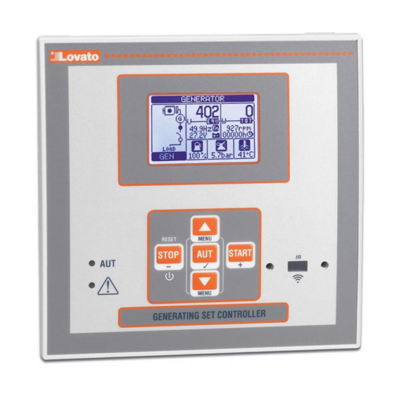
The RGK600 and RGK601 control units have been designed to offer
state-of-the-art functions for genset applications, both with and without
automatic mains outage control. Built with dedicated components and
extremely compact, the RGK600-RGK601 combine the modern design of
the front panel with practical installation and LCD screen that provides a
clear and intuitive user interface.
Page
1
2
3
3
3
3
4
4
5
7
8
8
8
9
9
10
10
10
12
12
13
14
25
26
26
28
30
31
32
33
34
37
37
38
39
29/08/2013
s. 1 / 39
Advertisement
Table of Contents

Subscribe to Our Youtube Channel
Related Manuals for LOVATO ELECTRIC RGK600


Summary of Contents for LOVATO ELECTRIC RGK600
-
Page 1: Table Of Contents
Wprowadzenie Introduction Urządzenia RGK600 i RGK601, w dwóch wykonaniach: z kontrolą The RGK600 and RGK601 control units have been designed to offer parametrów sieci i do agregatów wolnostojących, zostały zaprojektowane state-of-the-art functions for genset applications, both with and without by zapewnić funkcje niezbędne w aplikacjach sterowania agregatami. -
Page 2: Opis
Description 4 dostępne wersje: 4 versions available: RGK600 – z funkcja kontroli sieci i wej. czujnika prędkości RGK600 – AMF with Pick-up speed input RGK600SA – do jedn. wolnostojących i wej. czujnika prędkości RGK600SA – Stand alone with Pick-up speed input RGK601 –... -
Page 3: Funkcje Przycisków
AUT Mode (Atomatic) – The AUT mode is highlighted by the relative podświetlona. Silnik kontrolowany przez RGK600 jest uruchamiany green LED. The engine of the RGK600 is started automatically in the automatycznie, gdy parametry sieci są poza limitami i zatrzymywany, kiedy case of a mains outage (outside the set limits) and stops when the mains parametry sieci powracają... -
Page 4: Menu Główne
Status wejść/wyjsć Lista konfiguracji Lista zdarzeń Input/output status List of events Menu Główne (RGK600) Main menu (RGK600) Hasło dostępu Password access Hasło używane jest do udzielania dostępu lub blokowania dostępu The password is used to enable or lock the access to setting menu ... -
Page 5: Tabela Wyświetlanych Stron
Tabela wyświetlanych stron Table of display pages STRONA PRZYKŁAD PAGES EXAMPLE Strona Główna Home page Tekst opisu Ekwiwalent Generator Equivalent Total (RGK600-RGK601) (RGK600-RGK601) agregatu (P01.10) napięcia całkowita identification text voltage power (P01.10) Status Run/stop silnika engine status Częstot., Frequency, RPM, RPM, Napięcie w... - Page 6 Prędkość silnika Engine speed Uwaga: Wskaźnik Z poziomu tej strony Note: prędkości możliwe jest From this page it is automatyczne possible to acquire Speed ustawienie proporcji automatically the ratio indicator pomiędzy RPM between RPM and W a sygnałem W. Zobacz frequency.
-
Page 7: Czujniki Rezystancyjne Paliwa, Temperatury I Ciśnienia
Czujniki rezystancyjne poziomu paliwa, temperatury chłodziwa Resistive sensors for fuel, oil and temperature i ciśnienia oleju • RGK600 can handle three analog resistive sensors for fuel level, engine RGK600 może obsługiwać trzy czujniki analogowe: poziomu paliwa, temperature and oil pressure. -
Page 8: Wejścia, Wyjścia, Zmienne Wewnętrzne, Liczniki
The following table groups all the I/O and the internal variables managed Poniższa tabela wskazuje wszystkie zmienne wewnętrzne zarządzane by the RGK600. przez RGK600. KOD. OPIS ILOŚĆ... -
Page 9: Zmienne Kontrolowane Zdalnie (Remx)
(OUTx), it will be possible to freely energise or de-energise one relay przekaźnikowych przy użyciu oprogramowania do zdalnej kontroli. through the supervision software. This allows to use the RGK600 relays to Ta funkcjonalność umożliwia stosowanie wyjść przekaźnikowych drive lighting or similar loads. -
Page 10: Automatyczny Test
By skasować jeden alarm, który posiada ustawioną blokadę, należy użyć To reset one alarm that has been programmed with latch, use the odpowiedniej komendy w menu komend. dedicated command in the commands menu. W celu zaprogramowania alarmów i ich definicję należy zapoznać For details on alarm programming and definition, refer to setup menu M32. - Page 11 Dostępne pomiary Supported measurements Port CAN umożliwia dekodowanie i udostępnianie zestawu pomiarów The CAN port is able to decode and make available a set of zdefiniowanych przez standardy J1939 a identyfikowanych po numerze measurements defined by the J1939 standard and identified by a number SPN (Suspect Parameter Number).
-
Page 12: Port Podczerwieni Ir Do Programowania
W przypadku wystąpienia kilku alarmów jednocześnie wyświetlane In the case of several simultaneus alarms, these are cycled periodically. są one cyklicznie w pewnych odstępach. W zależności od wagi kodu generowany jest wskaźnik alarmu: According to the seriousness of the code, an amber alarm indicator ... -
Page 13: Ustawienia Parametrów Przez Panel Przedni
Ustawienia parametrów przez panel przedni Parameter setting (setup) from front panel By otworzyć menu ustawień parametrów (setup): To open the parameters programming menu (setup): Należy przełączyć urządzenie w tryb STOP/RESET Turn the unit in STOP/RESET mode Przy normalnym wyświetlaniu pomiarów, należy jednocześnie In normal measurements view, press ▲▼simultaneously to call up wcisnąć... -
Page 14: Tabela Parametrów
By zmienić ustawienia parametru należy go wybrać i wcisnąć . To modify the setting of one parameter, select it and then press . Jeśli hasło dostępu zaawansowanego nie zostało wprowadzone If the Advanced level access code has not been entered, it will not be ... - Page 15 M02 - OGÓLNE Domyślnie Zakres M02 – GENERAL Default Range P02.01 Strona pierwotna przekładnika prądowego 1-10000 P02.01 CT Primary 1-10000 P02.02 Strona wtórna przekładnika prądowego P02.02 CT Secondary P02.03 Wartość odczytu przekładnika Obciążenie Obciążenie P02.03 CT Current valve Load Load Agregat Generator P02.04...
- Page 16 M07 – ENGINE SPEED Default Range P07.01 Źródło odczytu prędkości silnika W/czujnik P07.01 Engine speed reading source W/Pick-up (dla FREQ-AGR. (for FREQ-GEN. RGK600) W/czujnik RGK600) W/Pick-up CAN (dla CAN (for RGK601) RGK601) P07.02 Stosunek RPM / W - czujnik 1.0000 0.0001-50.000 P07.02 RPM/W ratio –...
- Page 17 …. …. P09.04 Przesunięcie dla czujnika rezystancyjnego -30.0 - +30.0 P09.04 Resistive sensor offset -30.0 - +30.0 P09.05 Jednostka pomiaru temperatury °C °C P09.05 Temperature measurement unit °C °C °F °F P09.06 Alarm wstępny dla temp.maksymalnej ° 20-300 P09.06 MAX. temperature prealarm °...
- Page 18 i rozruchem P11.09 Ilość prób rozruchu 1-30 P11.09 Number of attempted starts 1-30 P11.10 Czas trwania próby rozruchu 1-60 P11.10 Duration of attempted starts 1-60 P11.11 Przerwa pomiędzy próbami rozruchu 1-60 P11.11 Pause between attempted starts 1-60 P11.12 Przerwa między zakończeniem próby OFF/1-60 P11.12 Pause between end of attempted start and...
- Page 19 świec jest pobudzone przez ustawiony czas przed rozruchem. +Rozruch = wyjście energized for the set time before starting. +Start= The glowplugs output remains rozgrzewanie świec pozostaje pobudzone również podczas fazy rozruchu. +Cykl = energized also during the starting phase. +Cycle= The glowplugs output remains wyjście rozgrzewanie świec pozostaje pobudzone również...
- Page 20 P13.12 – Opóźnienie zadziałania dla częstotliwości minimalnej. P13.12 – Min. frequency intervention delay. P13.13 – OFF = kontrola sieci wyłączona INT = sieć kontrolowana przez sterownik RGK600. P13.13 – OFF = Mains control disabled. INT = Mains controlled by RGK600.
- Page 21 P14.12 – Min. frequency intervention delay. P14.13 – OFF = kontrola agregatu wyłączona INT = agregat kontrolowany przez sterownik P14.13 – OFF = Generator control disabled. INT = Generator controlled by RGK600. EXT = RGK600. EXT = kontrola agregatu wykonywana przez urządzenie zewnętrzne.
- Page 22 Uwaga: To menu zostało podzielone na 6 części, każda z 6 możliwych części odnosi OUT2, OUT3, OUT4, OUT5 and OUT6 , which can be managed by the RGK600. się do wyjść cyfrowych OUT1, OUT2, OUT3, OUT4, OUT5 i OUT6 które mogą...
- Page 23 żaden alarm. P23.04 – Type of connection between RGK600 and RGKRR relay remote unit. OFF = P23.04 – Typ podłączenia między RGK600 a RGKRR. OFF = komunikacja wyłączona. OUT= Communication disabled.
- Page 24 Komunikacja przez programowalne wyjście ustawione na funkcję Zdalne alarmy, for Remote alarms function, connected to the digital input of the RGKRR. CAN = The podłączone do cyfrowego wejścia w RGKRR. CAN = RGK600 i RGKRR komunikują RGK600 and RGKRR communicate through the CAN interface. Unless there are się...
-
Page 25: Alarmy
P25.n.01 – Signal that increments the count (on the output side). This may be the start-up of P25.n.01 – Sygnał który zwiększa stan licznika (po stronie wyjścia). Może być uruchomiony the RGK600 (ON), when a threshold is exceeded (LIMx), an external input is przez RGK600 (ON), przekroczony zostanie limit (LIMx), aktywacją zewnętrznego enabled (INPx), or for a logic condition (PLCx), etc. -
Page 26: Właściwości Alarmów
Czerwona dioda LED blisko ikony alarmu, na panelu przednim, będzie The red LED near the alarm icon on the front panel will flash when an alarm migać, gdy pojawią się warunki alarmowe. W synoptycznej części is active. In the area of synoptic on the display remains a flashing icon that wyświetlacza pozostaje migająca ikona odpowiadająca typowi alarmu. - Page 27 Błąd czujnika / sygnału W “Pick-up/W” signal fault ● ● ● ● ● ● ● ● ● ● Niska prędkość silnika “czujnik / “Pick-up/W” engine speed low ● ● ● ● ● ● ● ● ● ● sygnał W” Wysoka prędkość silnika “czujnik “Pick-up/W”...
-
Page 28: Opis Alarmów
Opis alarmów Alarm description DESCRIPTION ALARM EXPLANATION OPIS WYJAŚNIENIE ALARMU Ostrzeżenie, temperatura silnika Temperatura silnika jest wyższa niż poziom przed Engine temperature Engine temperature higher than prealarm (czujnik analogowy) alarmu ustawiony w P09.06. prealarm (analog sensor) threshold set in P09.06. Wysoka temperatura silnika Temperatura silnika jest wyższa niż... - Page 29 Maintenance request 3 Błąd systemu Błąd wewnętrzny RGK700. Zobacz rozdział Błędy System error RGK600 internal error. SeeSystem errors systemu w celu uzyskania możliwego chapter for possible solutions. rozwiązania. Zbiornik zbyt pusty Odpowiednie programowalne wejście sygnalizuje...
-
Page 30: Tabela Funkcji Wejść
Wyłącznik otwarty ręcznie Alarm generowany w trybie AUT podczas fazy Manual circuit breaker Alarm generated in AUT mode during the rozruchu, z pracującym silnikiem, kiedy wykryto open starting phase, with the engine running, when status ‘włączony’ wejścia zaprogramowanego the enabled state of the input programmed funkcją... -
Page 31: Tabela Funkcji Wyjść
Włącznie zwiększenia Zgoda na podłączenie obciążenia do sieci. Enable mains load Go-ahead for connection of load to mains. obciążenia sieci Niedostępne w RGK600SA. Not available on RGK600SA. Włącznie zwiększenia Zgoda na podłączenie obciążenia do agregatu. Enable generator load Go-ahead for connection of load to generator. obciążenia agregatu Zdalne przełączanie W trybie AUT, kiedy silnik został... -
Page 32: Menu Komend
Pobudzane, gdy trwa cykl wychładzania. Generator ready Indicates the RGK600 is in automatic mode and there are Agregat gotowy Wskazuje, że RGK600 jest w trybie AUT i nie ma żadnych no active alarms. aktywnych alarmów. Preheating valve Controls the fuel preheating valve See description of Zawór podgrzewania... -
Page 33: Instalacja
Instalacja Installation RGK600 jest dedykowany do montażu tablicowego. Przy właściwym RGK600 is designed for flush-mount installation. With proper mounting, it montażu zapewnia, od strony panelu przedniego, stopień ochrony IP65. guarantees IP65 front protection. Należy umieścić urządzenie w otworze montażowym; należy upewnić... -
Page 34: Schematy Połączeń
Należy wykonać tę samą operację dla czterech klipsów montażowych. Repeat the same operation for the four clips. Należy dokręcać wkręty z maksymalną siłą momentu obrotowego 0,5Nm Tighten the fixing screw with a maximum torque of 0,5Nm. W przypadku konieczności deinstalacji należy wykonać... - Page 35 Schemat połączeń w układzie trójfazowym i komunikacją CAN bus Schemat połączeń w układzie trójfazowym i wejściami analogowymi wykorzystywanymi jako cyfrowe Wiring diagram for three-phase generating set with CAN bus Wiring diagram for three-phase generating set with analog imputs used communication port as digital inputs L3 N L3 N...
- Page 36 Schemat połączenia w układzie jednofazowym Schemat połączenia w układzie dwufazowym Wiring for single-phase generating set Wiring for two-phase generating set 36 37 39 40 46 47 49 50 51 54 55 36 37 39 40 21 20 49 50 51 54 55 Schemat połączenia agregatu z ciągłym ładowaniem alternatora magnetycznego...
-
Page 37: Rozkład Zacisków
Rozkład zacisków Terminals position MAINS CURRENT BATTERY 53 54 55 56 34 35 36 37 38 39 40 41 43 49 50 51 52 Wymiary mechaniczne i otwór montażowy (mm) Mechanical dimensions and front panel cut-out (mm) Doc: I378PLGB0214_RGK600_RGK600SA_RGK601_RGK601SA.doc 29/08/2013 s. -
Page 38: Dane Techniczne
Dane techniczne Technical characteristics Zasilanie pomocnicze Supply Napięcie znamionowe akumulatora 12 lub 24V= Battery rated voltage 12 or 24V= indifferently Maksymalny pobór prądu 90mA przy 12V= i 45mA przy 24V= Maximum current consumption 90mA at 12V= e 45mA at 24V= Maksymalny pobór mocy / rozproszenie 1,1W Maximum power consumption/dissipation... -
Page 39: Historia Wersji Oprogramowania
Wejścia prądowe Current inputs Prąd znamionowy Ie 1A~ lub 5A~ Rated current Ie 1A~ or 5A~ Zakres pomiaru dla skali 5A: 0,050 – 6A~ Measuring range for 5A scale: 0.050 – 6A~ dla skali 1A: 0,050 – 1,2A~ for 1A scale: 0.050 – 1.2A~ Typ wejścia bocznikowe, przez zewnętrzny Type of input...
Need help?
Do you have a question about the RGK600 and is the answer not in the manual?
Questions and answers