Table of Contents
Advertisement
Внимание!Технические описания и данные,
приведенные в данном руководстве, являются
наиболее полными на данный момент, но могут быть
изменены без предупреждения. Установка прибора
производится специально обученным персоналом, и в
полном соответствии с требованиям существующих
стандартов и нормативов во избежание несчастных
случаев.
Введение
Это простое устройство с понятным экраном для использования
пользователем неспециалистом в этой области. Данный прибор
обладает широким рядом функций, которые доступны лишь в более
сложных приборах.
Описание
Контроль генератора с функцией автоматического запуска (AMF)
Входы измерения трех фаз сети (L1-L2/N-L3)
Вход измерения однофазной сети генератора (L1-L2/N)
Универсальное питание 12-24Vdc
1 экран типа LED с 4 характеристиками
19 LED индикаторов для режима и измерений
Клавиатура с 8 кнопками.
Порт связи RS-232 для программирования и удаленного контроля.
6 программируемых цифровых входов
6 программируемых релейных выходов (5НO + 1 C/O)
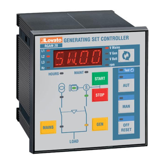
Клавиатура
Кнопки OFF/RESET, MAN и AUT – Нажимая эти кнопки можно
выбрать рабочий режим. Свечение индикаторов укажет выбранный
режим, мигание индикаторов- удаленный контроль активирован.
Кнопки START и STOP – Эти кнопки работают только в режиме
РУЧНОЙ и используются для пуска и останова двигателя. Нажав
кнопку START будет предпринята попытка пуска, удерживая эту
кнопку, время пуска будет увеличено. Мигание Led индикатора
двигателя указывает что он пущен с запретом сигналов; постоянное
свечение индикатора указывает на конец времени запрета сигналов.
Двигатель может быть остановлен кнопкой OFF/RESET.
Кнопки MAINS и GEN – Кнопки функционируют только в режиме MAN
и используются для переключения нагрузки на генератор и наоборот.
Свечение символов сети и генератора индикаторов указывает на
наличие соответствующего напряжения с установленными пределами.
Свечение символов переключателей указывает на замкнутое
состояние переключающего устройства; если символы мигают,
поступает некорректный сигнал от устройства переключения о
замыкании или оно разомкнуто.
Кнопка – используется для выбора измерения.
Рабочие режимы
Режим OFF/RESET – Двигатель не работает. Если присутствует сеть,
нагрузка переключена на MAINS. Если двигатель работает, при
изменении TEST, AUT или MAN на положение OFF/RESET двигатель
будет немедленно остановлен и сигналы сброшены. В случае
присутствия сигналов, сброс не возможен.
Режим MAN – Двигатель может запускаться и останавливаться в
ручном режиме только кнопками START и STOP, нагрузка
переключается на генератор и обратно кнопками MAINS и GEN. В
режиме MAN при нажатии и удержании кнопки старт время пуска
RGAM 20
Контроллер генератора с
функцией автоматического
запуска
РУКОВОДСТВО ПО ЭКСПЛУАТАЦИИ INSTRUCTIONS MANUAL
RGAM 20
Gen-set controller
with AMF function
(Automatic Mains Failure)
WARNING! This equipment is to be installed by qualified
personnel, complying to current standards, to avoid damages or
safety hazards. Products illustrated herein are subject to alteration
and changes without prior notice. Technical data and descriptions
in the documentation are accurate, to the best of our knowledge,
but no liabilities for errors, omissions or contingencies arising
therefrom are accepted.
Introduction
This simple, streamlined appliance features a clear, user-friendly front
panel that facilitates use also by less expert users. It is also equipped
with a wide range of control functions usually found only on higher range
appliances.
Description
Gen-set control with automatic management of the AMF (Automatic
Mains Failure) function
Three-phase mains measurement input (L1-L2/N-L3)
Single-phase gen-set measurement input (L1-L2/N)
12-24Vdc universal power supply unit
1 alphanumeric LED type display with 4 characters
19 LEDs for status and measurement display
8-key membrane keyboard
RS-232 communication interface for set-up, remote control and
supervision
6 programmable digital inputs
6 programmable relay outputs (5NO + 1 C/O)
Keyboard
OFF/RESET, MAN and AUT keys – Press these keys to select the
operating mode. The illuminated LED indicates the selected operating
mode; if it is flashing, remote control is active.
START and STOP keys – These work in MAN operating mode only,
used to start and stop the engine. By quickly pressing the START key,
one start attempt takes place; by keeping the START key pressed, the
duration of the start attempts can be extended. The flashing LED of the
engine symbol denotes engine started, with alarms inhibited; and is
constantly on at the end of the alarms inhibition time. The engine can be
stopped using the OFF/RESET key.
MAINS and GEN keys – They work in MAN operating mode only, used
to switch the load from mains to generator and vice versa. The
illuminated LEDs of the mains and generator symbols indicate the
respective voltages are within preset limits. The illuminated LEDs of the
changeover symbols indicate the actual closing of switching devices;
when flashing, there is an incorrect feedback signal for the actual closing
or opening of the switching devices.
Key – used to select the measurement to be displayed
Operating mode
OFF/RESET mode – The engine cannot operate. If the mains is present,
the load is switched to the mains. Changing from TEST, AUT or MAN to
the OFF/RESET mode and if the engine is running, the engine is
immediately stopped and eventual alarms are reset. If the cause of the
alarm is still present, it cannot be reset.
MAN mode – The engine can be manually started or stopped using the
START and STOP keys only, in addition to load switching from mains to
generator and vice versa, by means of the MAINS and GEN keys.
Always in MAN mode, at the start command and by keeping the key
p. 1 / 17
Advertisement
Table of Contents

Subscribe to Our Youtube Channel
Related Manuals for LOVATO ELECTRIC RGAM 20


Summary of Contents for LOVATO ELECTRIC RGAM 20
- Page 1 RGAM 20 RGAM 20 Контроллер генератора с Gen-set controller функцией автоматического with AMF function запуска (Automatic Mains Failure) РУКОВОДСТВО ПО ЭКСПЛУАТАЦИИ INSTRUCTIONS MANUAL Внимание!Технические описания и данные, WARNING! This equipment is to be installed by qualified приведенные в данном руководстве, являются...
- Page 2 будет увеличено, при удержании кнопки останова более чем на 6 сек, pressed, the preset starting time can be prolonged while at the stop топливный насос отключиться через 4 минуты. command and by keeping the key pressed for more than 6 seconds, the Режим...
- Page 3 МЕНЮ КОМАНД Код COMMANDS MENU Code C.01 – Сброс часов обслуживания M.RES C.01 – Maintenance hours reset M.RES C.02 – Сброс часов двигателя E.HOU C.02 – Engine hours clearing E.HOU C.03 – Сброс часов работы RENT C.03 – Rent hours reset RENT C.04 –...
- Page 4 P0101 – Выбор языка для сигналов и текстов. P0101 –Selection of language for alarm and parameter texts P0102-03-04-05-06-07-08 – Установка виртуальных часов. P0102-03-04-05-06-07-08 – Setting of the virtual date clock P0109 – Активация автоматического доступа к часам при включении P0109 –Activation of automatic access for clock set-up at power-on P0110 –...
- Page 5 P0412 – Время работы реле функции СТОП магнето двигателя. P0411 – Time between disconnection of the load from the generator and stopping of the P0413 – Время между пуском двигателя и началом работы реле запрограммированного как engine. функция “GAS”. P0412 – Energization time of the relay programmed with the “STOP” stop magnet function. P0414 –...
- Page 6 сигналов активировано или не зависит то наличия сети или отсутствия ее. ON+GBL mains control in RESET mode is activated and the relay programmed P0614 – Смотрите описание P0613 в режиме MAN with global alarm function is activated or not according to whether the mains P0615 –...
- Page 7 P1001 Адрес серийного порта RS232 1-99 P1001 RS232 serial port address 1-99 P1002 Скорость RS232 9600 OFF/1200-38400 P1002 RS232 baud-rate 9600 OFF/1200-38400 P1003 Протокол Rs232 P.ASC AUTO P1003 RS232 communication protocol P.ASC AUTO Prop. ASCii Prop. ASCii Modbus RTU Modbus RTU P1004 Паритет...
- Page 8 P12.1.2 Тип контакта НО НО/НЗ P12.1.2 Contact type NO/NC P12.1.3 Задержка закрытия (s) 0.0-6000.0 P12.1.3 Closing delay (s) 0.0-6000.0 P12.1.4 Задержка открытия(s) 0.0-6000.0 P12.1.4 Opening delay (s) 0.0-6000.0 P12.2.1 Входная клемма6.2 Температура См. таблицу P12.2.1 Input terminal 6.2 Temperature See list below P12.2.2 Тип...
- Page 9 Сигнал зарядного Эта функция показывает сигнал от BAT.C Battery charger alarm This function indicates an external battery BAT.C устройства внешнего зарядного устройства. Сигнал charger alarm. The alarm is generated only генерируется только при наличии with the mains voltage present напряжения в сети User Alarm 1 User alarm input.
- Page 10 MODE Режимы работы OFF,MAN,AUT доступны на программируемом выходе как рабочие режимы. Коды параметров: R=RESET/OFF A=автоматический MODE OFF,MAN,AUT operating modes enable the output programmed as „operating mode‟. M=ручной The codes of the parameter correspond to: R=RESET/OFF A=Automatic M=Manual NO.MA Режим сети : См. таблицу колонка A NO.MA Mains status : see table below column A E.RUN...
- Page 11 скорости W не поступает течение 5 секунд. speed signal is not detected for 5 seconds. A10 – Происходит когда двигатель пущен (зарядное устройство генератора, A10 – Occurs when engine running is detected (battery charger alternator присутствует напряжение и/или частота генератора) и сигнал presence of the voltage and/or frequency of the generator) and the „W‟...
- Page 12 Установка сигналов (по умолчанию) Alarms setting (default values) High temperature Высокая температура Low oil pressure Низкое давление масла Неисправность датчика Oil pressure sensor fault масла Fuel shortage Низкий уровень топлива High battery voltage Высокое напряжение батареи Низкое напряжение Low battery voltage батареи...
- Page 13 -2 OPEN = открытие контактора генератора -2 OPEN = causes opening of the gen-set contactor -3 COOL = активация прцедуры охлаждения -3 COOL = enables the cooling procedure -4 STOP = немедленный останов -4 STOP = causes immediate stopping ...
- Page 14 Максимальное потребление мощности Maximum power consumption/dissipation 3W Пределы напряжения Voltage range 9…36VDC 936VDC Минимальное напряжение при пуске 6,7VDC Minimum voltage at the starting 6.7VDC Ток режима готовности 110mA -12VDC и 60mA при 24VDC Stand-by current 110mA at 12VDC and 60mA at 24VDC Чувствительность...
- Page 15 Степень защиты IP54 по фронту Degree of protection IP54 on front Вес 480g Weight 480g Соответствие стандартам Reference standards IEC/EN 61010-1, IEC/EN 55011, EN 50082-2, IEC/EN 60028-2-61, IEC/EN 61010-1, IEC/EN 55011, EN 50082-2, IEC/EN 60028-2-61, IEC/EN 60068-2-6 (LROS-Lloyd‟s Register Of Shipping), IEC/EN 60068-2-52 IEC/EN 60068-2-6 (LROS-Lloyd‟s Register Of Shipping), IEC/EN 60068-2-52 (RINA- (RINA-Italian Naval Register), UL 508 and CSA C22.2_N14-95 (cULus).
- Page 16 Присоединение с однофазным генератором Присоединение с генератором с системой постоянных магнитов Wiring for single-phase generating set Wiring for generating set with permanent magnet battery charger alternator C.B. REG. Блок клемм (реальный вид) Terminal block connections (rear view) M AI NS GENERATOR L2-N L2-N...
- Page 17 94,00 91,00 96,00 82,00 96.00 91,00 96,00 p. 17 / 17...
Need help?
Do you have a question about the RGAM 20 and is the answer not in the manual?
Questions and answers
Good day , i need to start generator by remote start . how do i program RGAM LOVATO CONTROLLER . The gen will get signal from inverter to stard up . Thanks
To program the RGAM 20 Lovato Electric controller for remote start of a generator, follow these steps:
1. Ensure Proper Installation: The controller must be installed by qualified personnel following relevant safety standards.
2. Select Operating Mode: Set the controller to AUT (Automatic Mode) using the operating mode selection.
3. Enable Remote Control: Ensure that the R.LOC (Remote Control Lock) is disabled to allow communication.
4. Connect External Start Signal: Use the appropriate external input to provide a remote start signal.
5. Verify External Generator Control: Ensure the E.GEN (External GEN Control) input is properly connected to monitor the generator voltage.
6. Test the Configuration: Initiate a test by sending a remote start signal and observing the controller’s response.
These steps enable remote starting of the generator using the RGAM 20 controller.
This answer is automatically generated