LOVATO ELECTRIC RGK600 Installation Manual
Generating set controller
Hide thumbs
Also See for RGK600:
- Instruction manual (43 pages) ,
- Installation manual (12 pages) ,
- Installation manual (12 pages)
Table of Contents
Advertisement
Available languages
Available languages
LOV TO ELECTRIC S.P. .
24020 GORLE (BERGAMO) ITALIA
VIA DON E. MAZZA, 12
TEL. 035 4282111
L
E
E-mail info@
ovato
lectric.com
L
E
Web
www.
ovato
lectric.com
NOTE: THE REL TIVE INSTRUCTIONS M NU L (I378) IS V IL BLE IN V RIOUS L NGU GES IN DOWNLO DS T THE GLOB L WEBSITE WWW.LOV TOELECTRIC.COM.
W RNING!
– Carefully read the manual before the installation or use.
– This equipment is to be installed by qualified personnel, complying to current standards, to avoid damages or safety hazards.
– Before any maintenance operation on the device, remove all the voltages from measuring and supply inputs and short-circuit the CT input terminals.
– The manufacturer cannot be held responsible for electrical safety in case of improper use of the equipment.
– Products illustrated herein are subject to alteration and changes without prior notice. Technical data and descriptions in the documentation are accurate, to the best of our knowledge, but no liabilities for errors,
omissions or contingencies arising there from are accepted.
– A circuit breaker must be included in the electrical installation of the building. It must be installed close by the equipment and within easy reach of the operator. It must be marked as the disconnecting device of the
equipment: IEC /EN 61010-1 § 6.11.
– Clean the instrument with a soft dry cloth; do not use abrasives, liquid detergents or solvents.
INTRODUCTION
The RGK6... control units have been designed to offer state-of-the-art functions for genset applications, both with and without automatic mains outage control. Built with dedicated components and extremely compact,
the RGK6... combine the modern design of the front panel with practical installation and LCD screen that provides a clear and intuitive user interface.
DESCRIPTION
– 5 versions available:
• RGK600 – AMF with Pick-up speed input
• RGK600SA – Stand alone with Pick-up speed input
• RGK601 – AMF with CAN bus interface
• RGK601SA – Stand alone with CAN bus interface.
• RGK610 – AMF with Pick-up speed input and 1 expansion module slot
– Genset control with automatic management of mains-generator switching (RGK600-RGK601-
RGK610) or remote starting management (RGK600SA-RGK601SA).
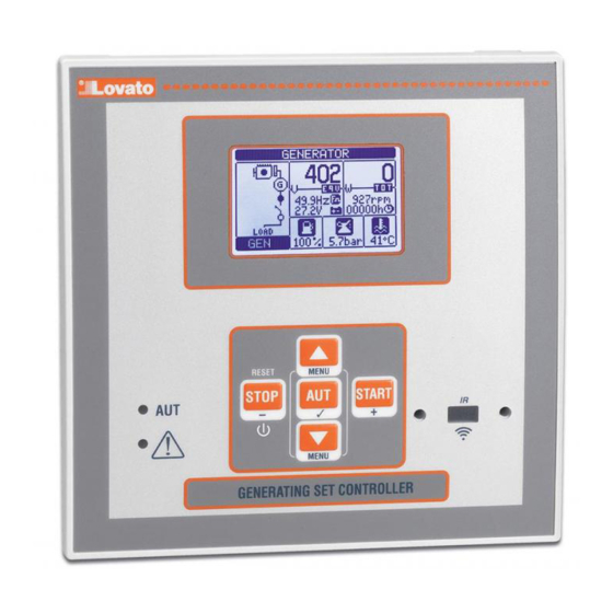
– 128x80 pixel, backlit LCD screen with 4 grey levels.
– 5 keys for function and setting.
– 2 LEDs indicate operating modes and states.
– 5-language text for measurements, settings and messages.
– Advanced programmable I/O functions.
– 4 alternative functions can be managed, selecting the same with a selector.
– Fully user-definable alarms.
– High accuracy TRMS measurement.
– 3-phase + neutral mains voltage reading input.
– 3-phase + neutral genset voltage reading input.
– 3-phase load currents reading input.
– 12-24VDC universal battery power supply.
FRONT BUTTONS FUNCTIONS
STOP / RESET button - Performs a manual shutdown of the engine and then exit the Automatic (AUT green LED turns off). Use to reset the alarms.
UT button - Used to select the operation mode automatically. The green AUT LED lights.
ST RT button - Performs a manual start of the engine, and exits from the automatic mode, moving to manual mode. Holding it down you can manually extend the duration of cranking.
For RGK600, RGK601 and RGK610 pressing simultaneously START and s you can manually switch the mains contactor. Pressing simultaneously START and t you can manually switch the generator contactor.
For RGK600SA and RGK601SA press simultaneously START and s to close the generator contactor, and press simultaneously START and t to open the generator contactor.
Buttons s and t - Used to scroll through the display pages or to select the list of options in a menu. Simultaneously pressing t + s calls up the main menu with rotating icons.
FRONT LED INDICATIONS
UT LED (green) – Indicates that the automatic mode is active.
larm LED (red) – Flashing, indicates an active alarm.
OPERATING MODES
To change the operating mode press for at least 0.5 sec the button correspondent to the desired mode.
STOP/RESET mode (Manual stop) - The engine will not start. The engine will stop immediately when this mode is selected- The mains contactor is closed. This mode reproduces the state of the RGK600-RGK601-
RGK610 when it is not powered. Use this mode to program the parameters and use the commands menu. The siren is disabled in STOP mode.
ST RT Mode (Manual start) - The engine is started manually (exiting AUT mode). It is possible to manually switch the load as explained in the Front button function chapter.
UT Mode ( utomatic) – The AUT mode is highlighted by the relative green LED. The engine of the RGK600-RGK601-RGK610 is started automatically in the case of a mains outage (outside the set limits) and stops
when the mains parameters are once again within said limits, on the basis of the times set in menu M13 Mains control. In the presence of voltage, the load is switched automatically in both directions.
The RGK600SA-RGK601SA is started and stopped remotely through a digital input (remote starting) normally controlled by an ATS. The load can be switched automatically or controlled remotely.
For both models, if the engine fails to start, the system continues attempting to start the engine up to the maximum number of programmed attempts. If the automatic test is enabled, it runs at the preset times.
GB
GENER TING SET CONTROLLER
Installation manual
RGK600 - RGK601 - RGK610
RGK600S - RGK601S
– Front optical programming interface: galvanically isolated, high speed, waterproof, USB and WiFi
compatible.
– 3 analog inputs for resistive sensors:
• Oil pressure
• Coolant temperature
• Fuel level
– 5+3 digital inputs:
• 4 programmable, negative
• 3 programmable, negative, used as an alternate function of resistive inputs
• 1 for emergency-stop pushbutton, positive
– 6 digital outputs:
• 6 protected positive static outputs
– Power control from external start (RGK600SA – RGK601SA)
– Engine speed reading W, pick-up and AC from permanent magnet b.c. input (RGK600-RGK600SA-
RGK610)
– CAN bus-J1939 engine ECU control communications interface (RGK601-RGK601SA).
– Memorization of last 50 events.
– Support for remote alarms.
– IP41 front protection. Upgrade to IP65 with optional gasket.
– Expandability with 1 EXP module (RGK610)
G
B
1
Advertisement
Table of Contents

Related Manuals for LOVATO ELECTRIC RGK600


Summary of Contents for LOVATO ELECTRIC RGK600
- Page 1 ST RT Mode (Manual start) - The engine is started manually (exiting AUT mode). It is possible to manually switch the load as explained in the Front button function chapter. UT Mode ( utomatic) – The AUT mode is highlighted by the relative green LED. The engine of the RGK600-RGK601-RGK610 is started automatically in the case of a mains outage (outside the set limits) and stops when the mains parameters are once again within said limits, on the basis of the times set in menu M13 Mains control.
-
Page 2: Installation
POWER-UP – RGK600, RGK601 and RGK610 (AMF versions) are switched on directly by applying power to battery terminals. – RGK600SA and RGK601SA (stand-alone versions) instead have an electronic switch-on/off circuit. With power applied, to switch on the unit press and hold STOP button for 1 sec. To switch off the unit press and hold STOP button for 5 sec. -
Page 3: Wiring Diagrams
WIRING DIAGRAMS Wiring diagram for three-phase generating set with “W” input signal Wiring diagram for three-phase generating set with “Pick-up” input signal L3 N L3 N 36 37 39 40 46 47 49 50 51 54 55 36 37 39 40 46 47 49 50 51 54 55... -
Page 4: Mechanical Dimensions And Front Panel Cut-Out (Mm)
WIRING FOR SINGLE-PHASE GENERATING SET WIRING FOR TWO-PHASE GENERATING SET 36 37 39 40 21 20 49 50 51 54 55 36 37 39 40 46 47 49 50 51 54 55 WIRING FOR GENERATING SET WITH PERMANENT MAGNET BATTERY CHARGER ALTERNATOR 36 37 39 40... - Page 5 TECHNICAL CHARACTERISTICS Supply Current inputs Battery rated voltage 12 or 24V= indifferently Rated current Ie 1A~ or 5A~ Maximum current consumption 90mA at 12V= and 45mA at 24V= Measuring range for 5A scale: 0.050 – 6A~ for 1A scale: 0.050 – 1.2A~ Maximum power consumption/dissipation 1.1W Type of input Shunt supplied by an external current transformer (low voltage).
- Page 6 Modo ST RT (Start manuale) - Il motore viene avviato manualmente (si esce dal modo AUT). E’ possibile la commutazione manuale del carico con le modalità descritte nel precedente capitolo Funzioni dei tasti frontali. Modo UT (Automatico) - La modalità AUT è evidenziata dalla accensione del corrispondente LED verde. Per RGK600-RGK601-RGK610, il motore viene avviato automaticamente in caso di assenza rete (fuori dai limiti impostati) e fermato al rientro della stessa, secondo tempi e soglie impostati nel menu M13 Controllo rete.
-
Page 7: Menu Principale
MESSA IN TENSIONE – RGK600, RGK601 e RGK610 (versioni AMF) vengono alimentati direttamente collegando tensione ai morsetti di batteria. – RGK600SA e RGK601SA (versioni stand-alone) hanno invece un circuito di accensione e spegnimento elettronico. Con alimentazione collegata, per accendere l’apparecchio premere il tasto STOP per 1 sec . -
Page 8: Schemi Di Connessione
SCHEMI DI CONNESSIONE Schema di collegamento per gruppi elettrogeni trifase con ingresso “W” Schema di collegamento per gruppi elettrogeni trifase con ingresso “Pick-up” L3 N L3 N 36 37 39 40 46 47 49 50 51 54 55 36 37 39 40 46 47 49 50 51... -
Page 9: Dimensioni Meccaniche E Foratura Pannello (Mm)
SCHEMA DI COLLEGAMENTO PER GRUPPI ELETTROGENI MONOFASE SCHEMA DI COLLEGAMENTO PER GRUPPI ELETTROGENI BIFASE 36 37 39 40 21 20 49 50 51 54 55 36 37 39 40 46 47 49 50 51 54 55 SCHEMA DI COLLEGAMENTO PER GRUPPI ELETTROGENI CON ALTERNATORE CARICABATTERIA A MAGNETI PERMANENTI 36 37 39 40... - Page 10 CARATTERISTICHE TECNICHE limentazione Ingressi amperometrici Tensione nominale di batteria 12 o 24V= indifferentemente Corrente nominale Ie 1A~ o 5A~ Corrente massima assorbita 90mA a 12V= e 45mA a 24V= Campo di misura per scala 5A: 0,050 – 6A~ per scala 1A: 0,050 – 1,2A~ Potenza massima assorbita/dissipata 1,1W Tipo di ingresso...
Need help?
Do you have a question about the RGK600 and is the answer not in the manual?
Questions and answers