Advertisement
Quick Links
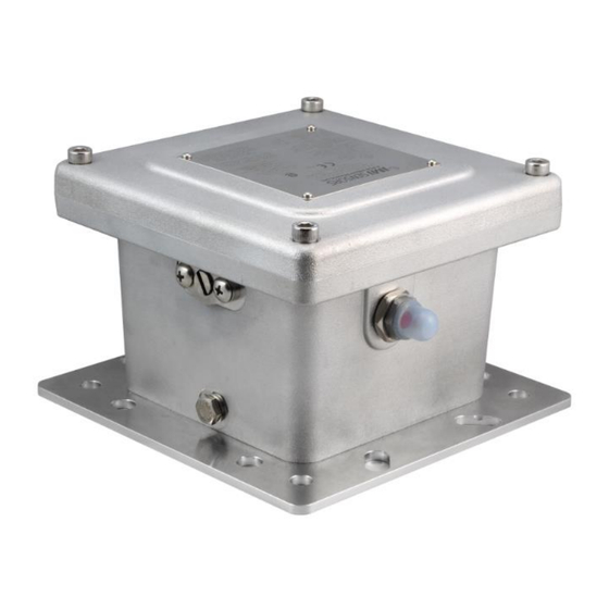
Model EX685A09
Intrinsically safe, linear adjust mechanical switch, 0 to 7 g's, 0 to 100 Hz, pushbutton reset
Installation and Operating Manual
For assistance with the operation of this product,
contact the PCB Piezotronics, Inc.
Toll-free: 800-959-4464
24-hour SensorLine: 716-684-0001
Fax: 716-684-3823
E-mail: imi@pcb.com
Web: www.imi-sensors.com
Advertisement

Subscribe to Our Youtube Channel
Related Manuals for PCB Piezotronics IMI SENSORS EX685A09


Summary of Contents for PCB Piezotronics IMI SENSORS EX685A09
- Page 1 Intrinsically safe, linear adjust mechanical switch, 0 to 7 g’s, 0 to 100 Hz, pushbutton reset Installation and Operating Manual For assistance with the operation of this product, contact the PCB Piezotronics, Inc. Toll-free: 800-959-4464 24-hour SensorLine: 716-684-0001 Fax: 716-684-3823 E-mail: imi@pcb.com...
- Page 2 Assistance is needed to safely operate equipment PCB Piezotronics is an ISO-9001 certified company whose Damage is visible or suspected calibration services are accredited by A2LA to ISO/IEC Equipment fails or malfunctions 17025, with full traceability to SI through N.I.S.T.
- Page 3 CAUTION Refers to hazards that could damage the instrument. NOTE Indicates tips, recommendations and important information. The notes simplify processes and contain additional information on particular operating steps. The following symbols may be found on the equipment described in this manual: This symbol on the unit indicates that high voltage may be present.
- Page 4 PCB工业监视和测量设备 - 中国RoHS2公布表 PCB Industrial Monitoring and Measuring Equipment - China RoHS 2 Disclosure Table 有害物质 镉 汞 铅 (Pb) 六价铬 (Cr(VI)) 多溴联苯 (PBB) 多溴二苯醚 (PBDE) 部件名称 (Hg) (Cd) 住房 PCB板 电气连接器 压电晶体 环氧 铁氟龙 电子 厚膜基板 电线 电缆 塑料 焊接...
- Page 5 Component Name Hazardous Substances Lead (Pb) Mercury (Hg) Cadmium (Cd) Chromium VI Polybrominated Polybrominated Compounds Biphenyls (PBB) Diphenyl Ethers (Cr(VI)) (PBDE) Housing PCB Board Electrical Connectors Piezoelectric Crystals Epoxy Teflon Electronics Thick Film Substrate Wires Cables Plastic Solder Copper Alloy/Brass This table is prepared in accordance with the provisions of SJ/T 11364.
- Page 6 Model EX685A09/685A19/29/39 Mechanical Vibration Switch Operating Guide 3425 Walden Avenue, Depew, New York 14043-2495 Phone (716) 684-0003 Fax (716) 684-3823 Toll Free Line 1-800-959-4IMI MANUAL NUMBER: 77919 MANUAL REVISION: NR ECN NUMBER:...
-
Page 7: Table Of Contents
Table of Contents Introduction ........................Page 3 General Features Warning Installation ........................Page 4 Internal Switches ......................Page 4 Remote Reset and Power On Delay ................Page 5-6 Setting Up The Switch ....................Page 6-7 Typical Installation Locations ..................Page 8-9 PAGE 2... -
Page 8: Introduction
Introduction The Mechanical Vibration Switch is a shock sensitive mechanism for shutdown of engine or electric motor powered equipment. This switch uses a patented linear adjustment magnetic latch technology to ensure reliable operation. Pushing the reset button moves the tripping latch into a magnetically held position. A shock/vibration will move the magnet beyond this holding position, thus freeing the spring loaded tripping latch to transfer the contacts and shut down the machinery. -
Page 9: Installation
Installation: The vibration switch is sensitive to shock and vibration in all three planes of motion – up/down, front/back and side/side. Side/side (in the same plane as the reset pushbutton) is the most sensitive. For maximum sensitivity, mount the unit so that the side with the reset button is in-line with the direction of rotation of the machine. The vibration switch must be firmly attached/mounted to the machine so that all mounting surfaces are in rigid contact with the mounting surface of the machine. -
Page 10: Remote Reset And Power On Delay
Chassis Screw Terminal Remote Reset and Power On Delay Models EX685A19, EX685A29 and EX685A39 have provisions to reset the switch remotely. The vibration switch can be remotely reset after being tripped by applying the correct voltage across the reset terminal as shown below. -
Page 11: Setting Up The Switch
NOTE: If using the solenoid for a power on delay, do not exceed the “on” times listed. If the “on” time exceeds 4 minutes and/or the “off” time is shortened before energizing the solenoid again, the solenoid will be permanently damaged. - Page 12 Figure 1: Reset Button Figure 2: Sensitivity Adjustment Screw Figure 1A: Resetting the Switch Figure 2A: Adjusting the Sensitivity 3) Start the machine. 4) If the instrument trips on start-up, allow the machine to stop. Turn the sensitivity adjustment ¼ to ½ turn clockwise (less sensitive).
-
Page 13: Typical Installation Locations
Typical Installation Locations Cooling Tower Fan and Motor Reciprocating Compressor PAGE 8... - Page 14 Vibratory Screens PAGE 9...
- Page 15 Model Number Revision: NR VIBRATION SWITCH EX685A09 ECN #: 54129 OPTION AL VERSION S Performance EN GLISH Optional versions have identical specifications and accessories as listed for the standard model except Measurement Range 0 to 7 g pk 0 to 68.7 m/s² pk where noted below.
- Page 16 PCB Piezotronics Inc. claims proprietary rights in REVISIONS the information disclosed hereon. Neither it nor any reproduction thereof will be disclosed to others DESCRIPTION without the written consent of PCB Piezotronics Inc. RESET SWITCH RELEASED TO DRAFTING 54129 SENSITIVITY ADJUSTMENT...
- Page 32 Master Contract: 184981 Project: 70153084 Date Issued: 2017-11-21 Issued to: Industrial Monitoring Instr. (IMI) A Div. of PCB Piezotronics, Inc. 3425 Walden Ave Depew, New York 14043 Attention: Carrie Termin The products listed below are eligible to bear the CSA Mark shown with adjacent indicators 'C' and 'US' for Canada and US or with adjacent indicator 'US' for US only or without either indicator for Canada only.
- Page 33 Certificate: 70031613 Master Contract: 184981 Project: 70153084 Date Issued: 2017-11-21 CLASS 2258 02 PROCESS CONTROL EQUIPMENT - For Hazardous Locations CLASS 2258 82 PROCESS CONTROL EQUIPMENT - For Hazardous Locations – Certified to US Standards Ex d IIB T6 Gb Ex tb IIIC T85°C Db IP66 Class I, Zone 1 A/Ex d IIB T6 Gb Zone 21 AEx tb IIIC T85°C Db IP66...
- Page 34 Certificate: 70031613 Master Contract: 184981 Project: 70153084 Date Issued: 2017-11-21 The manufacturer is required to apply the following markings: • Products shall be marked with the markings specified by the particular product standard. • Products certified for Canada shall have all Caution and Warning markings in both English and French. Additional bilingual markings not covered by the product standard(s) may be required by the Authorities Having Jurisdiction.
- Page 35 Certificate: 70031613 Master Contract: 184981 Project: 70153084 Date Issued: 2017-11-21 This includes equipment supply, description of I/O connections and operating environmental conditions. Pollution degree 2; Installation category II; Altitude 2000m; Electrical supply 24Vdc, 120 Vac, 240 Vac Temperature 5°C to 40°C Do not exceed the maximum relay ratings as noted below.
- Page 36 Supplement to Certificate of Compliance Certificate: 70031613 (103164_0_000) Master Contract: 184981 The products listed, including the latest revision described below, are eligible to be marked in accordance with the referenced Certificate. Product Certification History Project Date Description 70153084 2017-11-21 Update 70031613 to revised construction of the Model 685A Series Mechanical Vibration Switch to include Zones and Divisions for North America hazardous locations certification.
Need help?
Do you have a question about the IMI SENSORS EX685A09 and is the answer not in the manual?
Questions and answers