Advertisement
Quick Links
Advertisement

Subscribe to Our Youtube Channel
Related Manuals for PCB Piezotronics IMI SENSORS 685A08


Summary of Contents for PCB Piezotronics IMI SENSORS 685A08
- Page 1 Model 685A08 Mechanical Vibration Switch Installation and Operating Manual For assistance with the operation of this product, contact PCB Piezotronics, Inc. Toll-free: 800-959-4464 24-hour SensorLine: 716-684-0001 Fax: 716-684-3823 E-mail: imi@pcb.com Web: www.imi-sensors.com...
- Page 2 Assistance is needed to safely operate equipment PCB Piezotronics is an ISO-9001 certified company whose Damage is visible or suspected calibration services are accredited by A2LA to ISO/IEC Equipment fails or malfunctions 17025, with full traceability to SI through N.I.S.T.
- Page 3 CAUTION Refers to hazards that could damage the instrument. NOTE Indicates tips, recommendations and important information. The notes simplify processes and contain additional information on particular operating steps. The following symbols may be found on the equipment described in this manual: This symbol on the unit indicates that high voltage may be present.
- Page 4 PCB工业监视和测量设备 - 中国RoHS2公布表 PCB Industrial Monitoring and Measuring Equipment - China RoHS 2 Disclosure Table 有害物质 镉 汞 铅 (Pb) 六价铬 (Cr(VI)) 多溴联苯 (PBB) 多溴二苯醚 (PBDE) 部件名称 (Hg) (Cd) 住房 PCB板 电气连接器 压电晶体 环氧 铁氟龙 电子 厚膜基板 电线 电缆 塑料 焊接...
- Page 5 Component Name Hazardous Substances Lead (Pb) Mercury (Hg) Cadmium (Cd) Chromium VI Polybrominated Polybrominated Compounds Biphenyls (PBB) Diphenyl Ethers (Cr(VI)) (PBDE) Housing PCB Board Electrical Connectors Piezoelectric Crystals Epoxy Teflon Electronics Thick Film Substrate Wires Cables Plastic Solder Copper Alloy/Brass This table is prepared in accordance with the provisions of SJ/T 11364.
- Page 6 Model 685A08 Mechanical Vibration Switch Model 685A08 Mechanical Vibration Switch Operating Guide 3425 Walden Avenue, Depew, New York 14043-2495 Phone (716) 684-0003 Fax (716) 684-3823 Toll Free Line 1-800-959-4IMI MANUAL NUMBER: 34377 MANUAL REVISION: NR ECN NUMBER:...
-
Page 7: Table Of Contents
Table of Contents Introduction........................Page 3 General Features Specifications ........................Page 4 Dimension Drawing ......................Page 5 Installation ........................Page 6 Typical Mounting Locations .................... Page 7 Internal Switches ......................Page 8 Electrical........................Pages 9-10 Sensitivity Adjustment ....................Page 11 PAGE 2... -
Page 8: Introduction
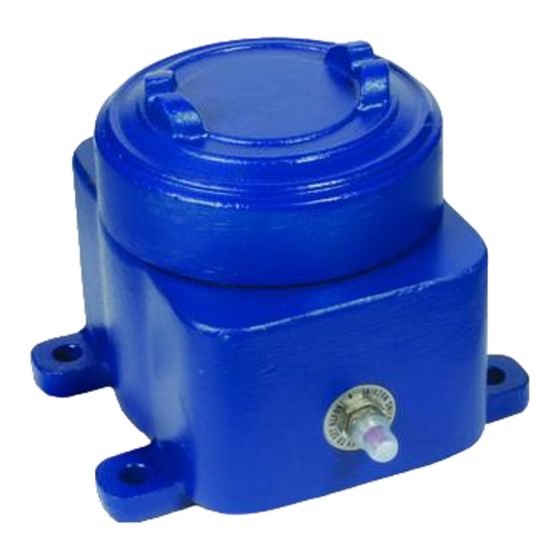
Introduction The Model 685AX8 Series Mechanical Vibration Switches are shock sensitive mechanisms for shutdown of engine or electric motor powered equipment. These switches use a magnetic latch to ensure reliable operation. Pushing the reset button moves the tripping latch into a magnetically held position. A shock/vibration will move the magnet beyond this holding position, thus freeing the spring loaded tripping latch to transfer the contacts and shutdown the machinery. -
Page 9: Specifications
Specifications • Sensing Geometry: …… Inertial Element • Vibration Range: …… 0-7g-peak • Alarm function Select: …… Latch • Alarm Relay: …… 5A Form C 480VAC, 2A Resistive, 1A Inductive @ 30VDC • Operating Temperature Range: …… -40 to 140°F (-40 to 60°C) •... -
Page 10: Dimension Drawing
The Model 685AX8 is designed to be mounted directly on the equipment to be monitored via integral mounting The Model 685AX8 is designed to be mounted directly on the equipment to be monitored via integral mounting holes. holes. 685A08 Dimension Drawing 685A18/A28 Dimension Drawing WARNING AC and DC input signals and power supply voltages could be hazardous. -
Page 11: Typical Mounting Locations
Disconnect all electrical power to the machine. Make sure the machine cannot operate during installation. Follow all safety warnings of the machine manufacturer. Read and follow all installation instructions. The 685AX8 Series vibration switches are sensitive to shock and vibration in all three planes of motion - up/down, front/back and side/side. - Page 12 RESET RESET RESET RESET RESET RESET RESET RESET RESET PAGE 7...
-
Page 13: Internal Switches
Internal Switches The 685A08 uses 2-SPDT switch terminals with removable screws for all connections (see below.) 685A08 Screw Connections The 685A18 and 685A28 use 1-SPDT switch terminals with removable screws for all connections (see below.) 685A18 & A28 Screw Connections Screw Connections: Normally Open Common... - Page 14 685A08 685A18/A28 PAGE 9...
- Page 15 685A08, A18, & A28 685A08, A18, & A28 PAGE 10...
-
Page 16: Sensitivity Adjustment
Sensitivity Adjustment WARNING: REMOVE ALL POWER BEFORE OPENING THE ENCLOSURE. IT IS YOUR RESPONSIBILITY TO HAVE A QUALIFIED PERSON PERFORM ADJUSTMENTS AND MAKE SURE IT CONFORMS TO NEC AND LOCAL CODES. DO NOT ADJUST SENSITIVITY WHILE THE MACHINE IS RUNNING. STAND CLEAR OF THE MACHINE AT ALL TIMES WHEN IT IS OPERATING.
Need help?
Do you have a question about the IMI SENSORS 685A08 and is the answer not in the manual?
Questions and answers