Advertisement
Quick Links
Advertisement

Related Manuals for PCB Piezotronics IMI SENSORS 685A09


Summary of Contents for PCB Piezotronics IMI SENSORS 685A09
- Page 1 Model 685A09 Mechanical Vibration Switch Installation and Operating Manual For assistance with the operation of this product, contact PCB Piezotronics, Inc. Toll-free: 800-959-4464 24-hour SensorLine: 716-684-0001 Fax: 716-684-3823 E-mail: imi@pcb.com Web: www.imi-sensors.com...
- Page 2 Piezotronics, user servicing or repair is critical test. not recommended and, if attempted, may void the factory warranty. Routine PCB Piezotronics maintains an ISO- maintenance, such as the cleaning of 9001 certified metrology laboratory and electrical connectors, housings, and offers calibration services, which are...
- Page 3 50% of the general contact numbers are: replacement cost returned item(s). PCB will provide a price PCB Piezotronics, Inc. quotation replacement 3425 Walden Ave. recommendation for any item whose Depew, NY14043 USA repair costs would exceed 50% of...
- Page 4 PCB工业监视和测量设备 - 中国RoHS2公布表 PCB Industrial Monitoring and Measuring Equipment - China RoHS 2 Disclosure Table 有害物质 汞 镉 六价铬 (Cr(VI)) 多溴联苯 (PBB) 多溴二苯醚 (PBDE) 部件名称 铅 (Pb) (Hg) (Cd) 住房 PCB板 电气连接器 压电晶体 环氧 铁氟龙 电子 厚膜基板 电线 电缆 塑料 焊接...
- Page 5 Component Name Hazardous Substances Lead Mercury Cadmium Chromium VI Polybrominated Polybrominated (Pb) (Hg) (Cd) Compounds Biphenyls Diphenyl (Cr(VI)) (PBB) Ethers (PBDE) Housing PCB Board Electrical Connectors Piezoelectric Crystals Epoxy Teflon Electronics Thick Film Substrate Wires Cables Plastic Solder Copper Alloy/Brass This table is prepared in accordance with the provisions of SJ/T 11364.
- Page 6 Model 685A09/685A19/29/39 Mechanical Vibration Switch Operating Guide 3425 Walden Avenue, Depew, New York 14043-2495 Phone (716) 684-0003 Fax (716) 684-3823 Toll Free Line 1-800-959-4IMI MANUAL NUMBER: 56534 MANUAL REVISION: A ECN NUMBER: 43636...
-
Page 7: Table Of Contents
Table of Contents Introduction ........................Page 3 General Features Warning Installation ........................Page 4 Internal Switches ......................Page 4 Remote Reset and Power On Delay ................Page 5-6 Setting Up The Switch ....................Page 6-7 Typical Installation Locations ..................Page 8-9 PAGE 2... -
Page 8: Introduction
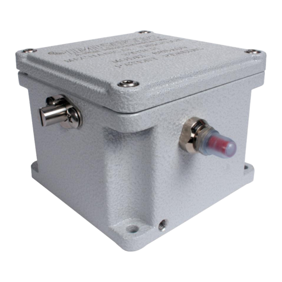
Introduction The Mechanical Vibration Switch is a shock sensitive mechanism for shutdown of engine or electric motor powered equipment. This switch uses a patent pending linear adjustment magnetic latch technology to ensure reliable operation. Pushing the reset button moves the tripping latch into a magnetically held position. A shock/vibration will move the magnet beyond this holding position, thus freeing the spring loaded tripping latch to transfer the contacts and shut down the machinery. -
Page 9: Installation
Installation: The vibration switch is sensitive to shock and vibration in all three planes of motion – up/down, front/back and side/side. Side/side (in the same plane as the reset pushbutton) is the most sensitive. For maximum sensitivity, mount the unit so that the side with the reset button is in-line with the direction of rotation of the machine. The vibration switch must be firmly attached/mounted to the machine so that all mounting surfaces are in rigid contact with the mounting surface of the machine. -
Page 10: Remote Reset And Power On Delay
Chassis Screw Terminal Remote Reset and Power On Delay Models 685A19, 685A29 and 685A39 have provisions to reset the switch remotely. The vibration switch can be remotely reset after being tripped by applying the correct voltage across the reset terminal as shown below. NOTE: There is no positive/negative polarity needed for the wiring. -
Page 11: Setting Up The Switch
685A29 Only – A 120VAC power supply is needed to remotely reset the switch by energizing a solenoid. Upon applying 120VAC to the solenoid, the unit will need 184mA to energize the remote reset coil. At standard ambient temperature, the solenoid has a 25% “on” 75% “off” cycle. Maximum allowed On Time ( remote reset energized ) versus minimum Off Time ( remote reset de-energized ) On Time ( 25% ) Off Time ( 75% ) - Page 12 Figure 1: Reset Button Figure 2: Sensitivity Adjustment Screw Figure 2A: Resetting the Switch Figure 2A: Adjusting the Sensitivity 3) Start the machine. 4) If the instrument trips on start-up, allow the machine to stop. Turn the sensitivity adjustment ¼ to ½ turn clockwise.
-
Page 13: Typical Installation Locations
Typical Installation Locations Cooling Tower Fan and Motor Reciprocating Compressor PAGE 8... - Page 14 Vibratory Screens PAGE 9...
- Page 15 Model Number Revision: C MECHANICAL VIBRATION SWITCH 685A09 ECN #: 43636 Performance ENGLISH OPTIONAL VERSIONS Measurement Range 7 g pk 68.7 m/s² pk Optional versions have identical specifications and accessories as listed for the standard Frequency Range 0 to 6000 cpm 0 to 100 Hz model except where noted below.
- Page 16 PCB Piezotronics Inc. claims proprietary rights in REVISIONS the information disclosed hereon. Neither it nor any reproduction thereof will be disclosed to others DESCRIPTION without the written consent of PCB Piezotronics Inc. ADDED NOTE 1 46319 SENSITIVITY ADJUSTMENT RESET SWITCH SCREW 3.70 [94.0]...
Need help?
Do you have a question about the IMI SENSORS 685A09 and is the answer not in the manual?
Questions and answers