
Related Manuals for Body Solid Endurance CL300


Summary of Contents for Body Solid Endurance CL300
- Page 1 CL300 v. 091709 Endurance CL300 Climber ® by Body-Solid User Manual v. CL300-20230116...
-
Page 2: Table Of Contents
Table of Contents CONGRATULATIONS..................3 IMPORTANT SAFETY INSTRUCTION............4 SAFETY GUIDELINES.................5 - 6 REFERENCE DRAWING................7 HARDWARE PACK LIST................8 ASSEMBLY INSTRUCTION.................9 - 21 OPERATING YOUR CLIMBER..............22 - 23 OPERATING THE CONSOLE..............24 - 27 MONITORING YOUR HEART RATE............31 CHEST STRAP OPERATION...............32 MAINTENANCE....................33 PART LIST....................35 - 38 EXPLODED VIEW DIAGRAM..............39... -
Page 3: Congratulations
CONGRATULATIONS Congratulations!! Thank you for purchasing your new Endurance Climber. Using state-of-the-art techniques, robust frame structure and superior ergonomic design, Endurance Climber set a new standard for excellence. The En- durance Climber can improve your quality of life by keeping you fit and healthy, increasing your energy levels and enhancing your lifestyle. -
Page 4: Important Safety Instruction
The CL300 is designed for your enjoyment. By following these precautions and using com- mon sense, you will have many safe and pleasurable hours of healthful exercise with your Endurance CL300. After assembly, you should check all functions to ensure correct operation. If you experience problems, first recheck the assembly instructions to locate any possible errors made during assembly. -
Page 5: Safety Guidelines
Safety Guidelines Successful cardio training programs have one prominent feature in common...safety. Cardio training has some inherent dangers, as do all physical activities. The chance of injury can be greatly reduced or completely removed by using correct running techniques, proper breathing, maintaining equipment in good working condition, and by wearing the appropriate clothing. - Page 6 Safety Guidelines This exercise equipment is designed and built for optimum safety for home use. However, certain precautions always apply whenever you operate any exercise equipment. Be sure to read the entire manual before assembly and operation of this machine. Also, please note the following safety precautions.
-
Page 7: Reference Drawing
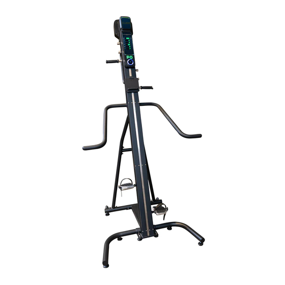
hours of quality exercise to make you feel better, look better, achieving a happier and healthier lifestyle. and enjoy life to its fullest. Before reading further, please review the drawing below and Reference Drawing It's a fact that a regular exercise program can improve your familiarize yourself with the parts that are labeled. Read this physical and mental health. Too often, our busy lifestyles limit manual carefully before using the CLIMBER. our time and opportunity to exercise. Console Monitor Handlebar Tablet Holder Right Side Handrail Left Side Handrail Main Frame Left Rear Support Left Pedal Right Pedal Rear Stabilizer Front Stabilizer 7 ... -
Page 8: Hardware Pack List
HARDWARE IDENTIFICATION CHART Hardware Pack List After unpacking the unit, open the hardware bag and make sure that you have all the following fasteners. Some fasteners may be already attached to the parts. Picture Parts Description Pre-assembled Socket Head Cap Screw, M8x14mm 24 pcs (include Spring Washer &... -
Page 9: Assembly Instruction
Assembly Instruction Assembly of the CL300 takes professional installers about 1/2 hour to complete. If this is the first time you have assembled this type of equipment, plan on significantly more time. Professional installers are highly recommended! However, if you acquire the appropriate tools, obtain assistance, and follow the assembly steps sequentially, the process will take time, but is fairly easy. - Page 10 Step 1 Be careful to assemble all components in the sequence they are presented. Note: Fully tighten bolts at the End of Step 1B. Attach Front Stabilizer (#2) to Center Connection Tube (#4) using: m8x70mm socket Head Cap screw (#105), Qty: 2 m8 lock Washer (#106), Qty: 2 m8 arc Washer (#107), Qty: 2 Attach Rear Stabilizer (#2) to Center Connection Tube (#4) using:...
- Page 11 Step 1 Above shows STEP 1 assembled and completed. mponents. ocket Head sher M8 Arc Washer ocket Head sher M8...
- Page 12 Step 2 Be careful to assemble all components in the sequence they are presented. Note: Do not fully tighten bolts until instructed Attach Left/Right Support Tube (#5L & #5R) to Support Connection Tube (#108) using: m8x14mm socket Head Cap screw with Washers (#109), Qty: 4 Attach Left/Right Support Tube (#5L &...
- Page 13 Step 2 Above shows STEP 2 assembled and completed.
- Page 14 Step 3 Be careful to assemble all components in the sequence they are presented. Note: Do not fully tighten bolts until instructed Attach Main Frame (#1) to Front Stabilizer (#2) using: m8x14mm socket Head Cap screw with Washers (#109), Qty: 4 Note: Please have at least two persons to lift and hold the Main Frame (#1) during this Step.
- Page 15 Step 3 Above shows STEP 3 assembled and completed.
- Page 16 Step 4 Be careful to assemble all components in the sequence they are presented. Note: Fully tighten bolts at the End of below Step. Attach Main Frame (#1) to Left/Right Support Tube (#5L & #5R) using: m8x14mm socket Head Cap screw with Washers (#109), Qty: 4 Note: Please have at least two persons to hold the Main Frame (#1) during this Step.
- Page 17 Step 4 Above shows STEP 4 assembled and completed.
- Page 18 Step 5 Be careful to assemble all components in the sequence they are presented. Note: Fully tighten bolts at the End of Step 4C. Attach Left Side Handrail (#6) to Main Frame (#1) using: m8x14mm socket Head Cap screw with Washers (#109), Qty: 4 Insert Right Side Handrail (#7) into Left Side Handrail (#6) Attach Right Side Handrail (#7) to Main Frame (#1) using: m8x14mm socket Head Cap screw with Washers (#109), Qty: 4...
- Page 19 Step 5 Above shows STEP 5 assembled and completed.
- Page 20 Step 6 Be careful to assemble all components in the sequence they are presented. Note: Fully tighten bolts at the End of each Step. Press the Spring loaded Handlebar Lock (#95) inward. Insert the Handlebar (#8)into the Spring Loaded Handlebar Lock (#95). Lock the Handlebar (#8) in place by rotating the Spring Loaded Handlebar Lock (#95) Attach Left / Right Foot Pedals (#14 / #15) on Left/Right Foot Pedal...
- Page 21 Step 6 Above shows STEP 6 assembled and completed.
-
Page 22: Operating Your Climber
BALANCE HANDLES Operating your Climber While stepping onto the climber, you may use the Balance Handles (6/7) to support yourself. It is a great tool to help you get on and get off easily without falling. TURN POWER ON Step onto the lower pedal and then grab the Balance Handles with both hands. Lift your body up with the support of Balance Handles. - Page 23 HANDLEBAR ADJUSTMENT BEGINNER’S GUIDE Our Handlebar (8) provide 3 different positions to fit with different height of people. HANDLEBAR ADJUSTMENT Operating your Climber To change the position, unlock the Handlebar (8) by pressing the Spring Handlebar Lock (95) inward. Rotate the Our Handlebar (8) provide 3 different positions to fit with different height of people.
-
Page 24: Operating The Console
Operating the Console... - Page 25 Operating the Console CONSOLE DISPLAY TIME: Workout time is accumulated under any workout mode, except for Time Countdown Program. - Display range: 00:00 ~ 99:59 MINUTES:SECONDS. DISTANCE: - Display the total height accumulated during the workout, except for Distance Countdown Program. - Unit displayed in feet or meter.
- Page 26 Operating the Console RESISTANCE LEVEL - Display resistance level on the bottom screen during exercise. - Turn the knob clockwise or counter-clockwise to change the resistance level. - Display range: 01-16 INITIAL SETUP POWER ON: - Press the “ON/OFF” switch to turn on the console POWER OFF: - Press the “ON/OFF”...
- Page 27 Operating the Console SMART KNOB OPERATION ROTATION: - Rotate clockwise or counter-clockwise to choose settings, programs and values. PRESS: - Press the knob to confirm settings, programs or values. - During Workout Mode, press the knob to pause the program. Press the knob again to resume the program.
- Page 28 Operating the Console DISTANCE COUNTDOWN (DIST): - Rotate the knob until the LED matrix displays “DIST” - Press the knob to go to distance setting. - Rotate the knob to change the target distance and press the knob to start the workout program.
- Page 29 Operating the Console - LED matrix screen display the numbers of cycle left during the workout. - Rotate Knob to change resistance level during workout. INTERVAL (I3): - Rotate the knob until the LED matrix displays “I3” - Press the knob to go to the cycle setting. - Rotate the knob to choose the numbers of cycle and press the knob to start the workout program.
- Page 30 target time and press the knob to confirm the setting. Target time is displayed at Time window. Operating the Console In the Preset Programs, Target Time will be divided equally into 16 sections. Each section will have different preset resistance level as shown below: Target time/16 = Time in each section Sections Programs...
-
Page 31: Monitoring Your Heart Rate
Monitoring Your Heart Rate FITNESS SAFETY The Heart Rate chart indicates average rate zones for different ages. A variety of different factors (including medication, emotional state, temperature and other conditions) can affect the target heart rate zone that is best for you. Your physician or health care professional can help you determine the exercise intensity that is appropriate for your age and condition. -
Page 32: Chest Strap Operation
Chest Strap Operation Your Endurance ® Climber has the capability to determine Heart Rate with the use of a Heart Rate Chest Strap. A Heart Rate Chest Strap can be purchased seperately. The frequency of the receiver is 5KHz It is suggested for the Chest Strap Transmitter that you position the transmitter as close to your heart as possible, against the skin, 1-2 inches below the pectoral muscles. -
Page 33: Maintenance
TO PREVENT SEVERE INJURIES AND MAINTAIN HEALTHY CONDITION, PLEASE CAREFULLY EVALUATE PERSONAL CAPABILITY AND MONITOR THE HEART RATE CONSTANTLY. STOP IMMEDIATELY IF YOU FEEL ANY KIND OF DISCOMFORT AND Maintenance CONSULT FOR PHYSICAL ADVICE FROM PROFESSIONALS. The safety and integrity designed into the CLIMBER can only be maintained when the CLIMBER is regularly CABLE ADJUSTMENT examined for damage and wear. - Page 34 Maintenance MAGNETIC BRAKE VALUE SETTING ADJUSTMENT - Resistance force level can be changed by changing the magnetic brake value - In the standby mode (P0), Press the Knob and hold it for 10 seconds. LED screen will display the default setting of the magnetic brake value. Rotate the knob to increase/ decrease the value with range from 30 - 50.
-
Page 35: Part List
Parts List Part# DesCriPtion PART# DESCRIPTION Main Frame Front Stabilizer Rear Stabilizer Base Connection Tube Left Support Tube Right Support Tube Left Side Handrail Right Side Handrail Handlebar Left Traveling Bracket Right Traveling Bracket Left Foot Pedal Connector Right Foot Pedal Connector Handlebar Adjustment Base Motor Bracket Cable Adjustment Bracket... - Page 36 Bearing Spacer Front Cover Parts List Back Cover Braking System Motor Aluminum Alloy Pulley Part# DesCriPtion Bearing 6000 C Ring Φ26 Roller Guide Rail ø ø ø Roller 41.5 35.5 28.5mm Base of Bearing 6004 Bearing 6004 Belt Pulley Axis Belt Pulley Belt D8M15-760mm...
- Page 37 Phillips Pan Head Self-Tapping Screw, ST4.2x16mm Phillips Pan Head Screw, M4x30mm Parts List Button Head Cap Screw, M5x8mm Button Head Cap Screw, M6x8mm Flat Washer M6 Part# DesCriPtion Socket Head Cap Screw, M4x20mm Button Head Cap Screw, M6x12mm Socket Head Cap Screw, M6x16mm Spring Washer M6 Socket Head Cap Screw, M8x10mm Socket Head Cap Screw, M8x40mm...
- Page 38 Open End Wrench 13-15-17mm Roller Protector Long Parallel Key Parts List Short Parallel Key Spring Handlebar Lock Spring Handlebar Lock Axis Part# DesCriPtion Handlebar Sleeve LED Console ø ø Nylon Spacer 5x 6mm Socket Head Cap Screw, M5x37mm Socket Head Cap Screw, M5x45mm Socket Head Cap Screw, M5x10mm Flat Washer 16*6.2*1.5T Socket Head Cap Screw, M8x70mm...
-
Page 39: Exploded View Diagram
Exploded View Diagram PRODUCT PARTS DRAWING 94 93 24 27 24 27 24 27 76 77... - Page 40 Serial Number is Located on the Frame CL300 Model Name Purchase Date : _______________________________ Serial Number : 017979-_______________________ Customer Tech Support Hotline Toll Free: 1-800-556-3113 Phone: 1-708-427-3555 Fax: 1-708-427-3556 Hours: M-F 8:30-5:00 CST E-Mail: service@bodysolid.com Copyright 2009. Body-Solid. All rights reserved. Body-Solid reserves the right to change design and specifications when we feel it will improve the product. Body-Solid machines maintain several patented and patent pending features and designs.
Need help?
Do you have a question about the Endurance CL300 and is the answer not in the manual?
Questions and answers