Table of Contents
Advertisement
Advertisement
Table of Contents

Related Manuals for Body Solid EXM2500


Summary of Contents for Body Solid EXM2500
- Page 1 EXM2500 Assembly Instructions / Owner’s Manual...
-
Page 2: Table Of Contents
Contents Before You Begin . . . . . . . . . . . . . . . . . . . . . . . . . . . . . 3 Dimensions . -
Page 3: Before You Begin
Before You Begin Thank you for purchasing the EXM2500 . This gym is part of the Body-Solid line of quality strength training machines, which let you target specific muscle groups to achieve better muscle tone and overall body conditioning . -
Page 4: Dimensions
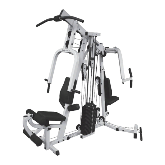
Dimensions The dimensions of the EXM2500 are: length 85 .4” x width 61 .3” x Height is 83” . The diagrams below are without the optional Leg Press Station GLP2500 . 85 .4” EXM2500 Top View Location of your Serial Number... -
Page 5: Preparations
. Assembly of the EXM2500 takes professional installers about 3-5 hours to complete . If this is the first time you have assembled this type of equipment, plan on significantly more time . -
Page 6: Important Safety Instructions
• Do not remove any safety labels from the machine. • Assemble and operate the EXM2500 on a solid, • Do not allow children on or near the equipment. level surface. Locate the unit a few feet from the •... -
Page 7: Warning, Safety & Maintenance
Warning, Safety & Maintenance Be sure that all users carefully read and understand all warning, safety and maintenance labels on the machine before use . Failure to do so may result in serious injury . It is imperative that you retain this Owner’s Manual and be sure all warning labels are legible and intact . - Page 8 Check slack in cables and re-adjust cable tension tance to ensure the maximum safety and performance if needed. See pages 54-55. of the EXM2500. Body-Solid uses the highest quality materials available, but wear is inevitable. • Check that locking nut at the Weight Stack is tight.
-
Page 9: Safety Guidelines
Safety Guidelines Successful resistance training programs have one prominent feature in common . . .safety . Resis- tance training has some inherent dangers, as do all physical activities . The chance of injury can be greatly reduced or completely removed by using correct lifting techniques, proper breathing, maintaining equipment in good working condition, and by wearing the appropriate clothing . -
Page 10: Parts List
EXM2500 Parts List Part # Description Main Base Frame 2” x 2” Rear Stabilizer 2” x 2” Upright 2” x 4” Upright 2” x 2” Front Stabilizer Leg Extension Main Frame 2” x 4” Top Frame 2” x 2” Seat Pad Frame Leg Ext . -
Page 11: Parts Diagram
EXM2500 Parts Diagram Main Base Frame 2” x 2” Rear Stabilizer 2” x 2” Upright 2” x 2” Front Stabilizer 2” x 4” Upright Leg Extension Main Frame 2” x 4” Top Frame Foot Brace Leg Ext . Seat Pad Frame 2”... - Page 12 EXM2500 Parts Diagram Seated Press Arms Leg Extension Seat Pad Pec Dec Seat Pad Foam Roller Bar (2) 2” x 2” Pulley Frame Pulley Rectangles (2) Double Pulley Holder Big Pulley Holder Small Pulley Holder Guide Rods (2) Lat Bar...
-
Page 13: Hardware List
EXM2500 Hardware List Part # Description 1/2” x 5” Hex Head Bolt (10) 1/2” x 3” Hex Head Bolt ” x 7 ” Hex Head Bolt ” x 2 ” Hex Head Bolt ” x 2 ” Hex Head Bolt ”... - Page 14 EXM2500 Hardware List Part # Description (smaller) 3” Pulley Short Nylon Bushing 38 x 38 mm Rubber Pad ” Rubber Donut 2” x 2” Square Rubber Cap (10) Steel Bushing 4” x 8” Foam Roller 95 x 140mm Grip Tape...
-
Page 15: Hardware Diagram
EXM2500 Hardware Diagram d1(2) d2(3) d3(18) d4(1) d5(3) d6(21) d7(1) d8(2) d9(2) d10(2) d11(1) d12(10) d13(6) d15(2) d18(3) d19(1) d20(5) d21(4) d28(4) d29(1) d32(3) d33(2) d34(2) d35(2) d36(1) d37(1) d38(12) d39(2) d40(4) 15 15... - Page 16 EXM2500 Hardware Diagram ( Shown in actual size ) 16 16...
- Page 17 EXM2500 Hardware Diagram ( Shown in actual size ) 17 17...
-
Page 18: Assembly Instructions
STEP Be careful to assemble all components in the sequence they are presented. NOTE: STEP Finger tighten all hardware in this step. Do Not wrench tighten until end of Attach (2) Weight Stack Shims d33, (2) End Caps d3, and (2) Frame Levelers d32 to the bottom of Main Base Frame A, as shown . - Page 19 STEP 2” x 2” Upright 2” x 4” Upright 2” x 2” Front Stabilizer Foot Brace 2” x 2” Rear Stabilizer Main Base Frame...
- Page 20 STEP Be careful to assemble all components in the sequence they are presented. NOTE: STEP Finger tighten all hardware in this step. Do Not wrench tighten until end of Attach (1) End Cap d28 onto 2” x 4” Upright D, as shown . Attach (1) End Cap d5 onto 2”...
- Page 21 STEP 2” x 4” Top Frame 2” x 2” Pec Dec Top 2” x 2” Upright M10 x 16mm hex head bolt 2” x 4” Upright M10 washer 2” x 2” Pulley Frame Main Base Frame...
- Page 22 STEP Be careful to assemble all components in the sequence they are presented. NOTE: STEP Finger tighten all hardware in this step. Do Not wrench tighten until end of Attach Leg Extension Main Frame F to the 2” x 2” Front Stabilizer E using: (1) a17 1/2”...
- Page 23 STEP Foam Roller Bar 2” x 4” Upright 32 X 12 M8 washer bearing Leg Ext . Seat M8 x 15mm M12 X 75mm Pad Frame round bolt shaft Foam Roller Bar 2” x 2” Front Stabilizer Leg Extension Frame Leg Extension Main Frame...
- Page 24 STEP Be careful to assemble all components in the sequence they are presented. NOTE: STEP Finger tighten all hardware in this step. Do Not wrench tighten until end of Attach Leg Extension Seat Pad R to the Leg Ext . Seat Pad Frame I using: (2) a11 5/16”...
- Page 25 STEP Seated Row Foam Roller Bar Back Pad Leg Extension Seat Pad Leg Ext . Seat Pad Frame Seated Row Foam Roller Bar 2” x 4” Upright...
- Page 26 STEP Be careful to assemble all components in the sequence they are presented. NOTE: STEP Finger tighten all hardware in this step. Do Not wrench tighten until end of Attach Seated Press Arms P to the 2” x 4” Top Frame G using: This hardware is pre-installed in Seated Press Arm P, loosen both allen head bolts to remove shaft, install and then re-tighten.
- Page 27 STEP Need to Loosen Both Allen Head Bolts in Order to Remove Shaft 19 X 180L shaft 2” x 4” Top Frame Seated Press Arms...
- Page 28 STEP Be careful to assemble all components in the sequence they are presented. NOTE: STEP Finger tighten all hardware in this step. Do Not wrench tighten until end of At this point make sure that the gym is in the right location. Insert (2) Guide Rods X into the Main Base Frame A .
- Page 29 STEP Weight Stack Top 2” x 4” Top Frame Guide Rods Guide Rods Main Base Frame...
- Page 30 STEP Be careful to assemble all components in the sequence they are presented. NOTE: STEP Finger tighten all hardware in this step. Do Not wrench tighten until end of Attach Right Pec Dec Arm N (there is a Red dot on this piece) onto the top of 2”...
- Page 31 STEP M10 x 16mm hex head bolt Right Pec Dec Arm M10 washer Right Pec Dec Handle 1/2” nylon lock nut Left Pec Dec Arm 2” x 2” Pec Dec Top Left Pec Dec Handle...
- Page 32 STEP Be careful to assemble all components in the sequence they are presented. Attach (2) End Caps d3, and (1) End Cap d4 to the 2” x 2” Seat Pad Frame H as shown . Attach Pec Dec Seat Pad S to the 2” x 2” Seat Pad Frame H using: (2) a11 5/16”...
- Page 33 STEP Back Pad Pec Dec Seat Pad 2” x 2” Upright 2” x 2” Seat Pad Frame...
- Page 34 STEP Be careful to assemble all components in the sequence they are presented. NOTE: Finger tighten all hardware in this step. Do Not wrench tighten until the cables are installed. Insert (2) Pulleys d6 inside 2” x 4” Top Frame G, and attach using: (2) a5 3/8”...
- Page 35 STEP NOTE: Leave all hardware in this step finger tight. Do Not wrench tighten until the cables are installed. 2” x 4” Top Frame 2” x 4” Top Frame 2” x 4” Top Frame 2” x 2” Upright 2” x 4” Top Frame...
- Page 36 STEP Be careful to assemble all components in the sequence they are presented. NOTE: Finger tighten all hardware in this step. Do Not wrench tighten until the cables are installed. Insert (2) Pulleys d6 into 2” x 4” Upright D, and attach using: (2) a5 3/8”...
- Page 37 STEP NOTE: Leave all hardware in this step finger tight. Do Not wrench tighten until the cables are installed. 2” x 4” Upright Main Base Frame 2” x 2” Pulley Frame Main Base 2” x 2” Pulley Frame Frame...
- Page 38 STEP Be careful to assemble all components in the sequence they are presented. NOTE: Finger tighten all hardware in this step. Do Not wrench tighten until the cables are installed. Insert (2) Pulleys d6 into Seated Press Arms P, and attach using: (2) a4 3/8”...
- Page 39 STEP NOTE: Leave all hardware in this step finger tight. Do Not wrench tighten until the cables are installed. Weight Stack Top Seated Press Arms Weight Stack Top Seated Press Arms...
- Page 40 STEP Be careful to assemble all components in the sequence they are presented. Lat Pulldown Cable (d23) Ball Stop End Metal Ball End 4045 mm 13’ 3 1/4”...
- Page 41 STEP NOTE: Remove finger tightened pulleys as needed. Do Not wrench tighten until the cables are installed. 2” x 4” Top Frame NOTE: Ensure that cable Lat Pulldown You can remove and reinstall travels over this Cable pulleys as needed. pivot shaft Start at the front of the gym .
- Page 42 STEP NOTE: Remove finger tightened pulleys as needed. Do Not wrench tighten until the cables are installed. Seated Press Arms 2” x 4” Upright Remove the top pulley in Seated Press Frame D and route Cable d23 around the top of pulley Reinstall top Pulley into Seated Press Frame D with the cable routed completely around it .
- Page 43 STEP NOTE: Remove finger tightened pulleys as needed. Do Not wrench tighten until the cables are installed. 2” x 4” Upright Double Pulley Holder Route the Lat Pulldown Cable d23 from 2” x 4” Upright D through the top of the Double Pulley Holder U2 and then install a Pulley as shown using: (1) a8...
- Page 44 STEP Top of Weight Selector Lat Pulldown Cable Bolt Allen Bolt Weight Selector Metal Ball Remove the Nut and Bolt in the top of the Weight Selector Bar d19 . Slide the Lat Pulldown Cable d23 through the opening in the top of the Weight Selector Bar d19 as shown . Attach Weight Stack Cable Bushing a18 to the Metal Ball End of the Lat Pulldown Cable d23 and tighten the Allen Screw .
- Page 45 STEP Be careful to assemble all components in the sequence they are presented. Pec Dec Cable d25 Metal Ball End Metal Ball End 1640 mm 5’ 4” Right Pec Dec Arm Left Pec Dec Arm Pec Dec Cable...
- Page 46 STEP NOTE: Remove finger tightened pulleys as needed. Do Not wrench tighten until the cables are installed. Right Pec Dec Arm Left Pec Dec Arm Pec Dec Cable Small Pulley Holder Attach one end of the Pec Dec Cable d25 into the Right Pec Dec Arm N . Route the Pec Dec Cable d25 over the top of Pulley and under Pulley Cable Guide d18 as shown .
- Page 47 STEP Be careful to assemble all components in the sequence they are presented. Mid Pulley Cable d26 Chain End Ball Stop End 1500 mm 4’ 11” Pec Dec Cable Small Pulley Holder 2” x 2” Upright Mid Pulley Cable...
- Page 48 STEP NOTE: Remove finger tightened pulleys as needed. Do Not wrench tighten until the cables are installed. Small Pulley Holder Mid Pulley Cable 2” x 2” Upright Pulley Rectangles NOTE: You can remove and reinstall pulleys as needed. Insert chain end of the Mid Pulley Cable d26 into the opening in 2” x 2” Upright C above the Back Pad, route the cable above the pulley and pull entire length through .
- Page 49 STEP Be careful to assemble all components 10.0 in the sequence they are presented. Long Cable (D24) Ball Stop End Stamped Eye End 7540 mm 24’ 8 3/4” Use the lower half of this floating pulley Small Straight Long Cable...
- Page 50 STEP NOTE: Remove finger tightened pulleys as needed. Do Not wrench tighten until the cables are installed. 10.1 Big Pulley Holder Use the lower half of Pulley Rectangles this floating pulley Main Base Frame 2” x 2” Pulley Frame Insert the Stamped Eye End of the Long Cable d24 into the Small Pulley Frame T under the pulley pull entire length of cable through .
- Page 51 STEP NOTE: Remove finger tightened pulleys as needed. Do Not wrench tighten until the cables are installed. 10.2 Double Pulley Holder Main Base Frame From Pulley route the Long Cable d24 up to Pulley attached to the bottom of Top Frame G and route the cable around Pulley .
- Page 52 STEP NOTE: Remove finger tightened pulleys as needed. Do Not wrench tighten until the cables are installed. 10.3 Route the Long Cable d24 forward from Pulley , and attach the Stamped Eye End to the Leg Extension Frame J as shown using: (1) a15 5/16”x 1 1/2”...
- Page 53 STEP Be careful to assemble all components in the sequence they are presented. Short Cable (d27) Chain End Stamped Eye End 950 mm 3’ 1 1/2” Big Pulley Holder Short Cable Main Base Frame Attach the Stamped Eye End of the Short Cable d27 to the hook on the bottom of the Big Pulley Holder V and attach the Chain End of the Short Cable d27 to the Main Base Frame A with a Snap Link d20 as shown .
-
Page 54: Cable Adjustments
Cable Adjustments Cables can stretch slightly when your gym is first used . If there is slack in the cables before resistance is felt, the cables should be tightened . Cable tension can be adjusted in several ways: Move the pulley up or down in Weight Stack Top M Move the pulley up or down in Double Pulley Holder U2 Adjust the chain attached to the Main Base Frame A Adjust the chain attached to the Small Pulley Holder W... - Page 55 Cable Adjustments Big Pulley Holder Short Cable Main Base Frame First, remove the Weight Stack Pin a13 from the Weight Stack . This will release tension on the cables . You can now adjust the Snap Link d20 located at the bottom of Short Cable d27 and attached to Main Base Frame A, to adjust the cable tension .
Need help?
Do you have a question about the EXM2500 and is the answer not in the manual?
Questions and answers
Can I replace the ball stop at the end of the weightlifting cable where the handlebar attaches?