Table of Contents
Advertisement
Advertisement
Table of Contents

Subscribe to Our Youtube Channel
Related Manuals for Body Solid Endurance R300


Summary of Contents for Body Solid Endurance R300
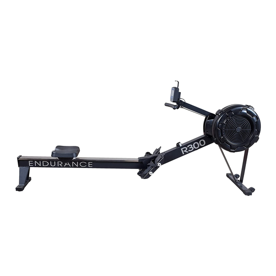
- Page 1 R300 v. 091709 Endurance R300 Rower ® by Body-Solid User Manual v. R300-062818...
-
Page 2: Table Of Contents
Table of Contents CONGRATULATIONS..................3 IMPORTANT SAFETY INSTRUCTION............4 SAFETY GUIDELINES.................5 - 6 ASSEMBLY INSTRUCTION.................7 - 19 OPERATING YOUR ROWER...............20 - 22 OPERATING THE CONSOLE..............23 - 25 MONITORING YOUR HEART RATE............28 CHEST STRAP OPERATION...............29 BUNGEE CORD ADJUSTMENT..............30 - 31 PART LIST....................32 - 34 EXPLODED VIEW DIAGRAM..............35... -
Page 3: Congratulations
CONGRATULATIONS Congratulations!! Thank you for purchasing your new Endurance Fan Rower. Using state-of-the-art techniques, robust frame structure and superior ergonomic design, Endurance Fan Rower set a new standard for excellence. The Endurance Fan Rower can improve your quality of life by keeping you fit and healthy, increasing your energy levels and enhancing your lifestyle. -
Page 4: Important Safety Instruction
The R300 is designed for your enjoyment. By following these precautions and using common sense, you will have many safe and pleasurable hours of healthful exercise with your Endurance R300. After assembly, you should check all functions to ensure correct operation. If you experience problems, first recheck the assembly instructions to locate any possible errors made during assembly. -
Page 5: Safety Guidelines
Safety Guidelines Successful cardio training programs have one prominent feature in common...safety. Cardio training has some inherent dangers, as do all physical activities. The chance of injury can be greatly reduced or completely removed by using correct running techniques, proper breathing, maintaining equipment in good working condition, and by wearing the appropriate clothing. -
Page 6: Safety Guidelines
Safety Guidelines This exercise equipment is designed and built for optimum safety for home use. However, certain precautions always apply whenever you operate any exercise equipment. Be sure to read the entire manual before assembly and operation of this machine. Also, please note the following safety precautions. -
Page 7: Assembly Instruction
Assembly Instructions Assembly of the R300 takes professional installers about 1/2 hour to complete. If this is the first time you have assembled this type of equipment, plan on significantly more time. Professional installers are highly recommended! However, if you acquire the appropriate tools, obtain assistance, and follow the assembly steps sequentially, the process will take time, but is fairly easy. - Page 8 Step 1 Be careful to assemble all components in the sequence they are presented. Note: Do not fully tighten bolts until instructed Attach Front Support Legs (#7 & #8) to Front Stabilizer (#4) using: m6x16mm socket Head Cap screw (#81), Qty: 4 m6 flat Washer (#76), Qty: 4...
- Page 9 Step 1 Above shows STEP 1 assembled and completed.
- Page 10 Step 2 Be careful to assemble all components in the sequence they are presented. Note: Fully tighten bolts at the End of each Step. Attach Front Support Legs (#7 & #8) to Main Frame (#1) using: m6x16mm socket Head Cap screw (#81), Qty: 4 m6 flat Washer (#76), Qty: 4...
- Page 11 Step 2 Above shows STEP 2 assembled and completed.
- Page 12 Step 3 Be careful to assemble all components in the sequence they are presented. Note: Fully tighten bolts at the End of each Step. Lift Up the Main Frame (#1) and Rail Frame (#2), then insert Rail Fram (#2) into the Main Frame (#1). Fit the Shaft (#24) on the Main Frame (#1) into the gap of the Rail Frame (#2).
- Page 13 Step 3 Above shows STEP 3 assembled and completed.
- Page 14 Step 4 Be careful to assemble all components in the sequence they are presented. Note: Fully tighten bolts at the End of each Step. Insert the Pull Pin (#98) into the Main Frame (#1) and Rail Frame (#2). Attach Console Monitor Post (#6) to the Side Covers (#57 & #58) using: m6x10mm Phillips Head screw (#72), Qty: 2...
- Page 15 Step 4 Above shows STEP 4 assembled and completed.
- Page 16 Step 5 Be careful to assemble all components in the sequence they are presented. Note: Fully tighten bolts at the End of each Step. Attach Pedal Support Plates (#5) to the Main Frame (#1) using: m8x150mm socket Head Cap screw (#84), Qty: 4 foot Pedal end Cap (#9), Qty: 4...
- Page 17 Step 5 Above shows STEP 5 assembled and completed.
- Page 18 Step 6 Be careful to assemble all components in the sequence they are presented. Note: Fully tighten bolts at the End of each Step. Attach Cell Phone Bracket (#20) to the Console Monitor (#19) using Rubber Band (#21). Attach the Console Monitor (#19) to the Console Mounting Bracket (#69) using: m8x75mm button Head Cap screw (#78), Qty: 1 m8 flat Washer (#79), Qty: 1...
- Page 19 Step 6 Above shows STEP 6 assembled and completed.
-
Page 20: Operating Your Rower
Operating your Rower MOVING THE ROWER The rower is easy to move around safely. To move the rower: 1. Lift the rear of the rower 2. Roll the rower on its front transport wheels to the desire location. 3. Gently lower the rear of the rower to the ground level STORING THE ROWER The rower can be seprated to minimize the unit size for storage. - Page 21 Operating your Rower DAMPER ADJUSTMENT There is a damper adjustment on the right side of the fan Shroud. The indicator can be moved up/down to adjust the damper. #1 is the lowest setting, #9 is the highest setting. HANDLEBAR POSITION Handlebar (#3) can be placed on the hook of the Console Monitor Post (#6) or it can be placed on the Handlebar Holder (#52).
-
Page 22: Operating Your Rower
Operating your Rower FOOT PEDAL ADJUSTMENT 1. Pull the Foot Pedal (#45) out of the two bulges of the Pedal PEDAL CAP ADJUSTMENT Support Plate (#5). Bulges The position of the PEDAL CAPS���� can be adjusted. Refer to the illustration. Pull the PEDAL CAP���� out from the two bulges 2. -
Page 23: Operating The Console
Operating the Console CONSOLE DISPLAY TIME: - Display flashing “00:00” for presetting the TIME program. Time can be set from 1:00 to 99:00 minutes - Displays the time during exercise. STROKE: - Display the total number of stroke during exercise PULSE: - Display the heart rate from 40 to 220 beats per minute during exercise. - Page 24 Operating the Console CALORIES: - Display flashing “100” for presetting CALORIES program. The target calories value can be set from 10 to 999 cals PADDLE WIDTH: - Display the distance per stroke. STROKE RATE: - Display the current stroke per minute during exerices. DISTANCE: - Display flashing “500”...
- Page 25 Operating the Console ENTER/STOP BUTTON: - Press the button to confirm the value in the program. - Press and hold the button for three seconds to reset the console program. - Press the button to pause the program during workout. INITIAL SETUP POWER ON: - Move the Handlebar or press any button.
- Page 26 Operating the Console 1. QUICK START PROGRAM To Quick Start the program, you can pull on the Handlebar (#30) to start. All fuction values fo the console will count up. For the other seven programs, press the “BACK” button to enter IDLE mode. Or press and hold the ”ENTER/STOP”...
- Page 27 We call this program Score Game, use SELECT button to 5. GAME PROGRAM: select the program. The �xed preset TI�E for the game is � minuets, this can’t be changed. Pull on the HANDLEBAR��� Operating the Console to run the program directly. When you complete the program, matrix display will show your point score and remind you with an audible alarm.
-
Page 28: Monitoring Your Heart Rate
Monitoring Your Heart Rate Fitness saFety The Heart Rate chart indicates average rate zones for different ages. A variety of dif- ferent factors (including medication, emotional state, temperature and other con- ditions) can affect the target heart rate zone that is best for you. Your physician or health care professional can help you determine the exercise intensity that is appro- priate for your age and condition. -
Page 29: Chest Strap Operation
Chest Strap Operation Your Endurance ® Fan Rower has the capability to determine Heart Rate with the use of a Heart Rate Chest Strap. A Heart Rate Chest Strap can be purchased seperately. It is suggested for the Chest Strap Transmitter that you position the transmitter as close to your heart as possible, against the skin, 1-2 inches below the pectoral muscles. -
Page 30: Bungee Cord Adjustment
Bungee Cord Adjustment The Bungee Cord (#38) may stretch after 250,000 Strokes. Please follow the instruction to properly adjust the tension of the Bungee Cord. 1. Position the Main Frame (#1) as shown in below Drawing. Remove the Main Frame Cap (#68) from the Main Frame (#1). Remove the bottom Cover (#70) from the Main Frame (#1). -
Page 31: Bungee Cord Adjustment
Bungee Cord Adjustment 4. Position the Main Frame (#1) as shown in the below Drawing. Slide the Bottom Cover (#70) back into the Main Frame (#1). Put the Main Frame Cap (#68) back into the Main Frame (#1). -
Page 32: Part List
Part List Part# DesCriPtion Main Frame Rail Frame Handlebar Front Stabilizer Pedal Support Plate Console Monitor Post Front Support Leg A Front Support Leg B Foot Pedal End Cap Seat Carriage Bungee Cord Hook Chain Bracket Rail Perforated Steel Mesh ø... - Page 33 Part List Part# DesCriPtion Damper Right Fan Shroud Left Fan Shroud Foot Pedal Foot Pedal Holder Pedal Strap ø ø Spacer, 16x30.5mm ø ø Pulley Spacer, 16x26.5mm Pulley Bushing Seat Handlebar Holder Upper Joint Cover Lower Joint Cover Generator Base Damper Cap Left Side Cover Right Side Cover...
-
Page 34: Part List
Part List Part# DesCriPtion Socket Head Cap Screw, M8x40mm Phillips Flat Head Screw, M6x16mm Socket Head Cap Screw, M8x150mm Socket Head Cap Screw, M8x110mm Button Head Cap Screw, M8x25mm Lock Washer, M8 Phillips Head Screw, ST4.2x16mm Phillips Head Screw,, M5x8mm Socket Head Cap Screw, M5x92mm Hex Nut, M5 Chain Hook... -
Page 35: Exploded View Diagram
Exploded View Diagram... - Page 36 E-Mail: service@bodysolid.com Copyright 2009. Body-Solid. All rights reserved. Body-Solid reserves the right to change design and specifications when we feel it will improve the product. Body-Solid machines maintain several patented and patent pending features and designs. All rights reserved on all design patents and utility patents.
Need help?
Do you have a question about the Endurance R300 and is the answer not in the manual?
Questions and answers