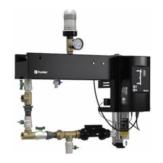
Summary of Contents for Puretec RI-EPAS
- Page 1 RI-EPAS Mounted End Point Acceptable Solution for the Water Services Act 2021 User Guide U L T R A V I O L E T...
-
Page 2: Table Of Contents
(Australia) or 0800 130 140 (New Zealand). Introduction The RI-EPAS Systems are designed to meet the requirements of the New Zealand Water Services Act (2021). As such all components within this kit should be used as specified within this user guide. For instructions on how to use and operate the included RI-NSFA system, please refer to the supplied RI-NSFA user guide. -
Page 3: Preparing Your System
Please read all instructions carefully as failures caused by incorrect installation or operation are not covered by warranty. Once your RI-EPAS system has been removed from the cartons, check to ensure all the components are present and have not been damaged in transportation. - Page 4 As a responsible manufacturer we care about the environment. We urge you to follow the correct disposal procedure for your product and packaging materials according to local laws and regulations. Installation & Operation Manual Copyright © Puretec Pty Ltd 2023...
-
Page 5: System Dimensions
System Dimensions RI-EPAS-2K Copyright © Puretec Pty Ltd 2023 RI-EPAS User Guide... - Page 6 System Dimensions RI-EPAS-4K 437 to 447 APPROX 1040.80 Installation & Operation Manual Copyright © Puretec Pty Ltd 2023...
- Page 7 System Dimensions RI-EPAS-6K Copyright © Puretec Pty Ltd 2023 RI-EPAS User Guide...
-
Page 8: Parts Diagrams
Parts Diagram Fig. 1 - Top Connections and Bracket Mounting Diagram (Same layout for RI-EPAS-2K, RI-EPAS-4K & RI-EPAS-6K) W. 1" Automatic Air Release Valve C. 1" Female Tee O. 1" Male to 1/2" Female Reducing Bush P. 1/2" to 1/4" Reducing Bush I. - Page 9 Parts Diagram Fig. 2 - RI-EPAS-2K Plumbing System Diagram RI-NSFA-2K Outlet Inlet A. Flow Meter J. 1" Female to Female Elbow B. 1¼" Male to 1" Male Reducing Adaptor K. 1" Female to Female Check Valve C. 1" Female Tee L.
- Page 10 Parts Diagram Fig. 3 - RI-EPAS-4K & RI-EPAS-6K Plumbing System Diagram Outlet RI-NSFA-4K or RI-NSFA-6K Inlet A. Flow Meter H. 1" PVC-U Pipe L. 1" BSPM to NPTM M. 1" Solenoid Valve B. 1¼" Male to 1" Male Reducing Adaptor Approx.
-
Page 11: Installation Diagram
(see RI-NSFA User Guide) Unit Pressure Gauge Sample Testing Point UV Shut-off Valves Bypass Valve Inlet (Additional straight lengths required if prefiltration isn't immediately installed 300mm Clearance at this point.) Drain Valve Copyright © Puretec Pty Ltd 2023 RI-EPAS User Guide... -
Page 12: Installation Requirements
Note: Hold off from gluing the PVC-U toe nipple to the PVC-U socket to allow for easier final assembly at step 6. 12 Installation & Operation Manual Copyright © Puretec Pty Ltd 2023... - Page 13 For RI-EPAS-2K Systems Connect the components on the vertical line using the 1” PVC-U toe nipple (F) as the last item to be connected (as shown in the RI-EPAS-2K diagram). For RI-EPAS-4K or RI-EPAS-6K Systems Connect the components on the vertical line using the 1” PVC-U pipe (H) as the last item to be connected.
- Page 14 UV chamber and outlet line onto the bracket, slotting the UV chamber into the designated location. Push the assembly down into the bracket to ensure it is seated properly. 14 Installation & Operation Manual Copyright © Puretec Pty Ltd 2023...
- Page 15 Inlet & outlet on the left side. Controller Inlet & outlet on the right side. Controller mounted on the right side. mounted on the left side. Copyright © Puretec Pty Ltd 2023 RI-EPAS User Guide...
- Page 16 17. Set up the RI-NSFA UV system following the instructions supplied in the RI-NSFA user guide. 18. The optional RI-COM unit can also be mounted and connected at this stage to the spare mounting point on the bracket. 16 Installation & Operation Manual Copyright © Puretec Pty Ltd 2023...
-
Page 17: Operation & Maintenance
Min/Max operating pressure : 103 - 861 kPa. • Min/Max influent water temperature : 2 - 40 °C (protect from freezing). • Nominal flow rate : Refer to model specific specification details. Copyright © Puretec Pty Ltd 2023 RI-EPAS User Guide... -
Page 18: Troubleshooting
Remove the air release valve and remove release valve. the air release valve. the grey casing to inspect for damage. The silicone components within the casing should not be disassembled. In the event of any other breakdown, please call Puretec Specifications Model RI-EPAS-2K RI-EPAS-4K RI-EPAS-6K Rated flow for NSF Std 38 Lpm (2.2 m3/hr) -
Page 19: Warranty
Puretec’s discretion, including chargeable inspection and labour costs incurred. Warranty/Australia This warranty is given by Puretec Pty Ltd, ABN 44 164 806 688, 37-43 Brodie Road Lonsdale SA 5160, telephone no. 1300 140 140 and email at sales@puretec.com.au. - Page 20 JUL2023...


Need help?
Do you have a question about the RI-EPAS and is the answer not in the manual?
Questions and answers