Table of Contents
Advertisement
Quick Links
NIPPON VALVE CONTROLS, INC.
Please read this manual before installation and use.
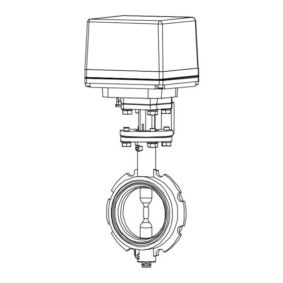
GENERAL
It composed of wafer type butterfly valve and high-power electric
actuator. (Proportional control)
Actuator
PDX : For AC / DC power.
PHX : For AC / DC power.
Valve
F
type FCD450 body.
FN type FCD450 body.
FE type Aluminum alloy diecast body. (lightweight)
FP type For Corrosion resistance. (Polypropylene body)
PRODUCT CODE
F type
FN type
(For JIS 5K / 10K)
FE type
FP type
(1) Actuator
PDX
PHX
(2) Valve
F- FN FE FP
(3) Voltage
1 : 100 / 110 V AC
2 : 200 / 220 V AC
0 : 24 V DC
3 : 24 V AC
Instruction manual
Electric Actuated Butterfly Valve
F -
F N
F E
F P
(1)
(2) (3) (4) (5) (6) (7) (8)
(4) Sizing code
(7) Disc material
0 : Standard
1 : Light
2 : Heavy
(5) Connection
1 : JIS 10K
(6) Body material
(8) Seat material
D : FCD450
L : ADC12
Q : PP
(9) Size [mm]
F FN FE FP
1 D
-
1 D
-
1 L T
-
1 Q Q E -
D : FCD450
U : SUSF316 / SCS14
A : CAC703
T : SCS13A
J : PPS
Q : PP
E : EPDM
B : NBR
V : FKM
ex. 80 A ® 080
1/13
OSRFN23A-EN
-
-
-
-
-
-
-
-
(9)
(10)
(11)
(10) Option
EA : Alarm output board
EI : 4 to 20 mA
Indication signal board
L0 : Auxiliary limit switch
L2 : Auxiliary limit switch
(11) Operation mode
Nil : Mode A
J : Mode B
(11) Input signal (PDX)
It corresponds to various
control input signals.
SP-1519
Advertisement
Table of Contents

Related Manuals for VPro F


Summary of Contents for VPro F
- Page 1 OSRFN23A-EN Instruction manual Electric Actuated Butterfly Valve F FN FE FP NIPPON VALVE CONTROLS, INC. SP-1519 Please read this manual before installation and use. GENERAL It composed of wafer type butterfly valve and high-power electric actuator. (Proportional control) Actuator PDX : For AC / DC power.
- Page 2 NOTE) • EPDM is not recommended for hydrocarbon-based oil or grease. • Hot water can be used at temperatures of up to 80 °C (FE: 90 °C). Steam cannot be used. • CAC703 and EPDM are suitable for seawater. (F, FN) INHERENT FLOW CHARACTERISTIC...
- Page 3 OSRFN23A-EN ELECTRIC ACTUATOR SPECIFICATIONS type Actuator type PDX-300- PDX-700- PDX-02K- PDX-06K- ( :Voltage code) Voltage 100 / 110 V AC ±10 % 50/60 Hz (Code: 1) 200 / 220 V AC ±10 % 50/60 Hz (Code: 2) 24 V AC ±10 % 50/60 Hz (Code: 3) 24 V DC...
- Page 4 OSRFN23A-EN ELECTRIC ACTUATOR SPECIFICATIONS WIRING Setting with DIP SW • Operation Positioner board Voltage Mode A Mode B (R core 100/110VAC transformer) 200/220VAC DIP SW 24VAC (100/110VAC) (200/220VAC) 24VDC Input signal (Operation range) 4 to 20mA • Input signal Motor 1 to 5V 4 to 20 mA / 1 to 5 V SHUT OPEN Resistance...
- Page 5 OSRFN23A-EN ELECTRIC ACTUATOR SPECIFICATIONS type Actuator type PHX-300- PHX-700- PHX-02K- PHX-06K- ( :Voltage code) Voltage 100 / 110 V AC ±10 % 50/60 Hz (Code: 1) 200 / 220 V AC ±10 % 50/60 Hz (Code: 2) 24 V AC ±10 % 50/60 Hz (Code: 3) 24 V DC...
- Page 6 OSRFN23A-EN ELECTRIC ACTUATOR SPECIFICATIONS WIRING Setting with DIP SW • Mode setup Positioner board Voltage Mode A Mode B (R core 100/110VAC transformer) DIP SW 200/220VAC 24VAC (100/110VAC) (200/220VAC) 24VDC Input signal (Operation range) 4 to 20mA Brushless • AC / DC mode change 1 to 5V DC motor ON ® AC power OFF ® DC power SHUT OPEN 0〜40% 50〜100%...
-
Page 7: Optional Parts
OSRFN23A-EN ELECTRIC ACTUATOR SPECIFICATIONS OPTIONAL PARTS Specifications Code No. PDX PHX Remarks Input signal 4 to 20 mA or 1 to 5 V Mode A (Standard) Mode B operation 0-135 to 0-1 k Potentiometer input or 0 to 5 V Mode A Mode B 0 to 10 V... - Page 8 OSRFN23A-EN ELECTRIC ACTUATOR SPECIFICATIONS DIMENSIONS PDX-300, 700 PDX-02K PDX-06K PHX-300, 700 PHX-02K PHX-06K 2-G1/2 2-G1/2 2-G1/2 Parts name Body Terminal block Transformer 13 Rubber packing Motor cover Limit switch 10 Drive shaft Motor SW setting cam 11 Manual clutch Control board Potentiometer 12 Manual shaft (For 06K) 8/13...
-
Page 9: Handling And Storage
• When you use a vinyl chloride flange, there is a caliber to be internal off the corners. Please cut off the corners with reference to the following. (F, FN) Valve size [mm] Chamfer [mm] •... -
Page 10: Other Notes
OSRFN23A-EN INSTALLATION, OPERATION & MAINTENANCE INSTRUCTIONS CAUTION ON PLASTIC VALVE (FP) OTHER NOTES Flange connection Until the wiring is completed there must be no condensation or flooding in the interior of the actuator, • Use same material as same as opposite piping after piping. -
Page 11: Operation
OSRFN23A-EN INSTALLATION, OPERATION & MAINTENANCE INSTRUCTIONS WIRING OPERATION PRECAUTIONS TESTING • Remove the actuator cover before wiring. • Make sure that power supply voltage is correct. Also • Two G1/2 electrical connections are provided with a check operating position, wiring, speed and signals. cable gland and plug. -
Page 12: Manual Operation
OSRFN23A-EN INSTALLATION, OPERATION & MAINTENANCE INSTRUCTIONS MANUAL OPERATION MAINTENANCE PRECAUTIONS • To prevent electric shock, be sure to turn off the power • Be sure to turn off the power before manual operation. when removing the actuator cover. • Operate manually with reference to the opening •... -
Page 13: Troubleshooting
OSRFN23A-EN INSTALLATION, OPERATION & MAINTENANCE INSTRUCTIONS TROUBLE SHOOTING Problem Cause Solution Problem Cause Solution Actuator Faulty wiring. Correct the wiring. Stop in the There is a Remove a foreign does not mid position. foreign object in object. move. the butterfly valve.
Need help?
Do you have a question about the F and is the answer not in the manual?
Questions and answers