Table of Contents
Advertisement
Quick Links
Technical Support and E-Warranty Certificate www.vevor.com/support
WOOD LATHE
INSTRUCTION MANUAL
MODEL: WL-1000GV
We continue to be committed to provide you tools with competitive price.
"Save Half", "Half Price" or any other similar expressions used by us only represents an
estimate of savings you might benefit from buying certain tools with us compared to the major
top brands and doses not necessarily mean to cover all categories of tools offered by us. You
are kindly reminded to verify carefully when you are placing an order with us if you are
actually saving half in comparison with the top major brands.
Advertisement
Table of Contents

Related Manuals for VEVOR WL-1000GV


Summary of Contents for VEVOR WL-1000GV
- Page 1 Technical Support and E-Warranty Certificate www.vevor.com/support WOOD LATHE INSTRUCTION MANUAL MODEL: WL-1000GV We continue to be committed to provide you tools with competitive price. "Save Half", "Half Price" or any other similar expressions used by us only represents an estimate of savings you might benefit from buying certain tools with us compared to the major top brands and doses not necessarily mean to cover all categories of tools offered by us.
- Page 2 CustomerService@vevor.com This is the original instruction, please read all manual instructions carefully before operating. VEVOR reserves a clear interpretation of our user manual. The appearance of the product shall be subject to the product you received. Please forgive us that we won't inform you again if there are any technology or software updates on our product.
-
Page 3: Matters Needing Attention
MATTERS NEEDING ATTENTION The information contained in this handbook is intended as a guide to the operation of these machines and does not form part of any contract.The data it contains has been obtained from the machine manufacturer and from other sources. We strive to ensure the accuracy of this information and try to verify each item and each data, but we cannot guarantee the full accuracy of the information, which means that the equipment supply may differ in detail from the description of the instructions. -
Page 4: Safety Warning
Our company reserves the right to make changes to this specification and product specifications. We will make continuous efforts to improve the quality of our products. All rights reserved. Reproduction or reproduction is not allowed without permission. SAFETY WARNING Symbol Symbol Description Warning - To reduce the risk of injury, user must read instructions manual carefully. - Page 5 Danger! Risk of personal injury or environmental damage! Risk of electric shock! Risk of personal injury by electric shock! Alternating current Never grab into the running machine! Remove chips and workpiece parts only if the machine is standing still! Never stop workpieces with the hand during run out! Never take measurements on a rotating workpiece! Do not wear safety gloves! Warning- Be sure to wear ear protectors when using this product.
- Page 6 Each time you work with an electrically operated machine, caution is advised! There is a risk of electric shock, fire, cutting injury; Protect the machine from dampness (causing a short circuit) Use power tools and machines never in the vicinity of flammable liquids and gases (danger of explosion) Check the cable regularly for damage Do not use the cable to carry the machine or to fix the workpiece...
- Page 7 WARNING: Read all safety warnings, instructions, illustrations and specifications provided with this machine. Failure to follow all instructions listed below may result in electric shock, fire and/or serious injury. Save all warnings and instructions for future reference. 1.The machine tool should be used by experienced personnel. If you are not familiar with the operation process of the lathe, do not use the machine tool at will.
-
Page 8: Remaining Risk Factors
15. Dress appropriately. Don't wear loose clothing, gloves, ties, rings, bracelets, jewelry, etc. To be on the safe side, For the sake of safety, wearing non-slip shoes. If you have long hair, please wear a work hat. 16. Wear protective glasses when operating. 17. -
Page 9: Technical Parameter
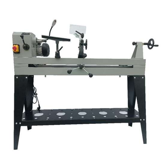
Risk of injury: hair and loose clothing, etc. can be captured and wound up! Safety regulations must be observed with regard to clothing. Risk of injury due to contact with live electrical components. Risk of injury due to dust emissions, treated with harmful agents ... - Page 10 Know Your Wood Lathe: (Fig. 1 ) PART NO. DESCRIPTION Stand Machine Bed Switch Head Stock Digital Indicator Spur Center Light Tool Rest Copying Device Living Center Tailstock Handwheel Digital Indicator Speed Controller Power Cord - 9 -...
-
Page 11: Standard Accessories
Standard accessories PART NO. DESCRIPTION Face Plate Wrench Rod Injection Lathe Tool Rest T-wrench Allen Wrench SW 3, SW 4 Stand accessories PART NO. DESCRIPTION Tool rack Stand Upper Cover Front Stand (Right) Front Stand (Left) Cup Head Square Neck Bolt M8 x 12 Washer 8 Bolt M8 x 16 Nut M8... -
Page 12: Intended Use
INTENDED USE The machine must only be used for its intended purpose! Any other use is deemed to be a case of misuse. To use the machine properly, you must also observe and follow all safety regulations, assembly instructions, and operating and maintenance instructions laid down in this manual. -
Page 13: Prohibited Use
The machine shall not be operated outdoors or in wet or damp areas. The machine shall not be operated in areas exposed to increased fire or explosion hazards. Prohibited use The operation of the machine outside the stated technical limits described in this manual is forbidden. -
Page 14: Preparatory Activities
ASSEMBLY Preparatory activities Delivery content Please check the product contents immediately after receipt for any eventual transport damage or missing parts. Claims from transport damage or missing parts must be placed immediately after initial machine receipt and unpacking before putting the machine into operation. Please understand that later claims cannot be accepted anymore. -
Page 15: Power Supply
This layer has to be removed. You can use standard solvents that do not damage the machine's surface. N O T I C E Do not use solvents based on nitrite or aggressive solvents like break cleaners or scrubbing agents! These damage the machine's surface. - Page 16 Assembly Prepare parts and install the stand as shown in right pictures. Assemble the stand according to the figure. Take care that screws are not tightened at the same time. Thus it is easier to position mounting holes and fix the screws.
- Page 17 Unmachined pieces or wood to be turned must be balance centred between carrying side (machine side) and the side of collateral run (tailstock) to avoid accidents as a result of possible tearing the workpiece off during machining! Pay attention to using roundwood or timber coming in parallel direction if possible.
- Page 18 Assembled lathe with stand Finally assembled lathe with clamped copying template COPYING ARM INSTALLATION Insert the copying arm between both holding butt straps located at the slide and shift the joint pin (item 73) to the bearing opening. Tighten nuts on both sides (Fig.
- Page 19 Then the tool support is fixed by clamping bolt in the supporting carrier of the tool (Fig. 9). Place the tool support as close to the workpiece as possible. The workpiece must not be in contact with the tool support during turning.
- Page 20 To turn plates or bowls remove the carrying point (Fig. 13) and turn the face plate to the spindle thread. For copying the copying arm must be installed between tailstock and carrying point. To place the copying device between tailstock and carrying point or face plate the gripping screws on the tailstock must be dismounted (Fig.
- Page 21 Copied original will be clamped between centring points of copying grips. Now moving in (holding-down pressure of the copying arm) can be adjusted using stressing screw (Fig. 17) Copying tool should be set to the largest diameter. The workpiece is then moved along the whole ...
-
Page 22: Operation
Loosen clamping screws of the holding lath (Fig. 21) to allow stretching of the template. During turning the template is moved along as often as required contour is formed at the workpiece W A R N I N G The leg set must be fastened to the supporting surface! ... -
Page 23: On/Off Switch
Operation instructions A T T E N T I O N Never switch the machine on while pressing the chisel against the material! N O T I C E Before switching the machine on, make sure that the tool rest is ... -
Page 24: Maintenance
N O T I C E You must move the lever to the lowest speed setting before turning the switch ON/OFF, otherwise the motor may not start! Tool rest N O T I C E The tool rest should be selected as close as possible to the workpiece! Height adjustment just below the centerline of the workpiece. -
Page 25: Maintenance Plan
N O T I C E Clean your machine regularly after every usage – it prolongs the machine's lifespan and is a prerequisite for a safe working environment. Repair jobs shall be performed by respectively trained professionals only! Maintenance plan After each work shift: Clean the machine and its parts with a strong jet of compressed air from wood dust and other material remain. -
Page 26: Troubleshooting
TROUBLE SHOOTING BEFORE YOU START WORKING ON THE ELIMINATION OF DEFECTS, DISCONNECT THE MACHINE FROM THE POWER SUPPLY Trouble Possible cause Solution Switch defective Repair switch Power supply is off Repair power supply Machine does not start Fuse is defective Change fuse Circuit breaker is active Push the circuit button... -
Page 27: Schaltplan / Wiring Diagram
N O T I C E Should you in necessary repairs not able to properly to perform or you not have the prescribed training for it always attract a workshop to fix the problem. SCHALTPLAN / WIRING DIAGRAM - 26 -... -
Page 28: Explosionszeichnung / Explosion Drawing
EXPLOSIONSZEICHNUNG / EXPLOSION DRAWING - 27 -... - Page 29 Part List for Wood Lathe Item Description Q'ty Item Description Q'ty Item Description Q'ty Hand wheel Taper shank Eccentric shaft Screw M6X10 Tailstock Flat head screw M5X20 Stand Tailstock spindle M24 Washer Φ6 Screw M6X8 Handwheel Washer Φ8 Mould plate Screw M8X8 Bolt M8X25 Mobile plate...
- Page 30 Retaining ring 62 Stud bolt Wrench S3 Bearing 6007-2Z Brush rest Wrench S4 Bracket-shifting lever Bearing 80201 "T"wrench Spring sliding guide Sharp tool Nut M8 3-way milling Head tool Screw M8X25 Gear-end pinion Arctool Shaft-pinion Handbook 37 Hex HD screw M8X25 2 Nut M10 Goggle 1 set...
- Page 32 Technical Support and E-Warranty Certificate www.vevor.com/support...
Need help?
Do you have a question about the WL-1000GV and is the answer not in the manual?
Questions and answers