Table of Contents
Advertisement
Technical Support and E-Warranty Certificate www.vevor.com/support
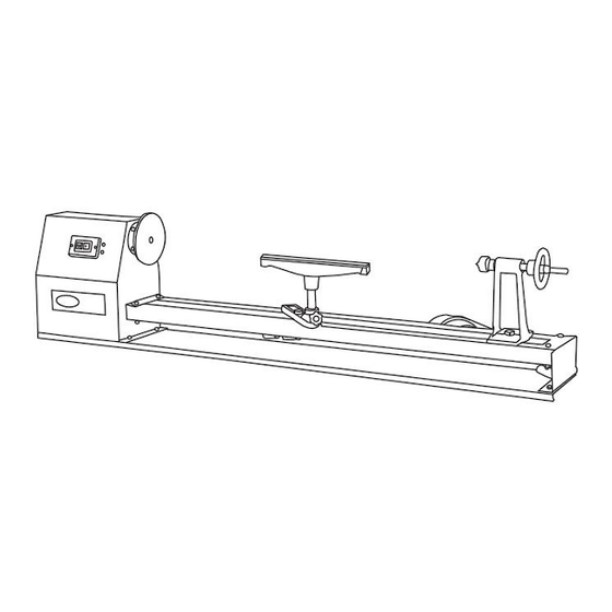
WOOD LATHE
INSTRUCTION MANUAL
MODEL: MCS1000
We continue to be committed to provide you tools with competitive price.
"Save Half", "Half Price" or any other similar expressions used by us only represents an
estimate of savings you might benefit from buying certain tools with us compared to the major
top brands and doses not necessarily mean to cover all categories of tools offered by us. You
are kindly reminded to verify carefully when you are placing an order with us if you are
actually saving half in comparison with the top major brands.
Advertisement
Table of Contents

Subscribe to Our Youtube Channel
Related Manuals for VEVOR MCS1000


Summary of Contents for VEVOR MCS1000
- Page 1 Technical Support and E-Warranty Certificate www.vevor.com/support WOOD LATHE INSTRUCTION MANUAL MODEL: MCS1000 We continue to be committed to provide you tools with competitive price. "Save Half", "Half Price" or any other similar expressions used by us only represents an estimate of savings you might benefit from buying certain tools with us compared to the major top brands and doses not necessarily mean to cover all categories of tools offered by us.
- Page 2 CustomerService@vevor.com This is the original instruction, please read all manual instructions carefully before operating. VEVOR reserves a clear interpretation of our user manual. The appearance of the product shall be subject to the product you received. Please forgive us that we won't inform you again if there are any technology or software updates on our product.
-
Page 3: Matters Needing Attention
MATTERS NEEDING ATTENTION The information contained in this handbook is intended as a guide to the operation of these machines and does not form part of any contract.The data it contains has been obtained from the machine manufacturer and from other sources. We strive to ensure the accuracy of this information and try to verify each item and each data, but we cannot guarantee the full accuracy of the information, which means that the equipment supply may differ in detail from the description of the instructions. -
Page 4: Safety Warning
Our company reserves the right to make changes to this specification and product specifications. We will make continuous efforts to improve the quality of our products. All rights reserved. Reproduction or reproduction is not allowed without permission. SAFETY WARNING Symbo Symbol Description Warning - To reduce the risk of injury, user must read instructions manual carefully. - Page 5 Danger! Risk of personal injury or environmental damage! Risk of electric shock! Risk of personal injury by electric shock! Alternating current Never grab into the running machine! Remove chips and workpiece parts only if the machine is standing still! Never stop workpieces with the hand during run out! Never take measurements on a rotating workpiece! Do not wear safety gloves! Warning- Be sure to wear ear protectors when using this...
- Page 6 The plug of an electrical tool must strictly correspond to the socket. Do not use any adapters together with earthed electric tools Each time you work with an electrically operated machine, caution is advised! There is a risk of electric shock, fire, cutting injury;...
- Page 7 WARNING: Read all safety warnings, instructions, illustrations and specifications provided with this machine. Failure to follow all instructions listed below may result in electric shock, fire and/or serious injury. Save all warnings and instructions for future reference. 1.The machine tool should be used by experienced personnel. If you are not familiar with the operation process of the lathe, do not use the machine tool at will.
- Page 8 14. To keep children out of the work area. The door should be locked when leaving the workshop. 15. Dress appropriately. Don't wear loose clothing, gloves, ties, rings, bracelets, jewelry, etc. To be on the safe side, For the sake of safety, wearing non-slip shoes.
- Page 9 Risk of injury to the hands / fingers by the rotating workpioece during operation. Risk of injury due to sharp edges of the workpiece, especially in non-fixed with a suitable tool / device workpiece. Risk of injury: hair and loose clothing, etc. can be captured and wound ...
-
Page 10: Technical Parameter
TECHNICAL PARAMETER Voltage 230 V / 50 Hz 110 V / 60 Hz Motor power 350W 885/1245/1715/2425RPM Spindle speeds Max. turning diamater Ø 350 mm Spindle diameter Ø 22 Spindle thread Distance between centers 970mm Tailostock spindle travel 10 mm Taper in Tail stock Spindle Weight N.W:23Kg;... - Page 11 Standard accessories PART NO. DESCRIPTION Rod injection Hex wrench S3 Wrench Fork wrench Face Plate Living center Spur center Lathe tool rest Plastic handle - 10 -...
-
Page 12: Intended Use
INTENDED USE The machine must only be used for its intended purpose! Any other use is deemed to be a case of misuse. To use the machine properly you must also observe and follow all safety regulations, the assembly instructions, operating and maintenance instructions lay down in this manual. - Page 13 Ambient conditions The machine may be operated: Humidity Max. 70% Temperature +5°С to +40°С (+41°F to +104°F) The machine shall not be operated outdoors or in wet or damp areas. The machine shall not be operated in areas exposed to increased fire or explosion hazard.
-
Page 14: Unpacking And Cleaning
UNPACKING AND CLEANING 1. Remove the woodworking lathe from the box 2. Check all the accessories of the machine tool according to the packing list. 3. Choose a location for the lathe that is dray, has good lighting and has enough room to be able to service the lathe on all four sides. - Page 15 The machine is very heavy. The machine shall be lifted from crate with a suitable lifting device only that is certified to be able to carry the machines load. W A R N I N G The lifting and transportation of the machine must only be carried out by qualified staff and must be carried out with appropriate equipment.
-
Page 16: Operating Adjustments
The grounding wire should be held in green-yellow. A damaged cable has to be exchanged immediately! Check, whether the feeding voltage and the Hz comply to the required values of the machine. A deviation of feeding voltage of ±5% is allowed. - Page 17 ADJUSTING SPEED Four spindle speeds of 1100,1600,2300 and 3400 RPM (885, 1245, 1715, 2425) are available with lathe.Chart-1 illustrates which ster of the pullevs the belt must be placed to obtain four speed.Chart-2 illustrates the proper speeds for workpiece. CHART-1 CHART-2 Disconnect the lathe from power source.
- Page 18 MOVING TAIL STOCK ASSWMBLY AND TOOL REST The tail stock assembly and tool rest are held to the bed with lock handle right underneath the bed rails.To move them to new position: 1. Disconnect the lathe from power source. 2. Loosen the lock handle with knob. 3.
- Page 19 REMOVING TAIL STOCK SPINDLE To remove the tail stock spindle from tail stock assembly: 1. Disconnect the lathe from power source. 2. Remove the hand wheel by loosening set screw with 1/8” hex wrench away from spindle.(as figure 1) 3. Unscrew tail stock spindle from tail stock assembly.(as figure 2) REMOVING DRIVE CENTER Drive stock center must be removed to attach to stock when spindle turning.
-
Page 20: Installing Faceplate
INSTALLING FACEPLATE The faceplate is supplid with your lathe. To install the faceplate: 1. Disconnect the lathe from power source. 2. Remove drive center from driving spindle. 3. Align the center hole of faceplate to the thread of spindle.(as figure) 4. -
Page 21: Operation
OPERATION Device to be operated in a perfect state only. Inspect the device visually every time it is to be used. Check in particular the safety equipment, electrical controls, electric cables and screwed connection for damage and if tightened properly. Replace any damaged parts before operating the device. -
Page 22: Hand Position
rest.(as figure 3) 10.Rotate the wood by hand to make sure that the comers do not strike the tool rest. 11.Review the speed setting suggested in the speed selection chart. 12.Readjust frequently as in step 9 as the stock diameter is reduced. HAND POSITION The position of your hands to the tool will be determined by the amount of leverage required. - Page 23 is,therefore,a very narrow tool(1/8” wide) and is shaped to cut its own clearance so that the edge will not be burned.When used for scraping, however, it should be backed off regularly to prevent overheating. Unlike the gouge and skew,the parting tool is seldom held with the bevel against the work.
- Page 24 shoulder down to the finished size. Hold the skew so the bottom edge of the bevel next to the shoulder will be very nearly parallel to the side of the shoulder. Made sure this is with the cutting edge turned away at the top, so that only the extreme toe will do the cutting.If the cutting edge is flat against the shoulder the chisel will run.
- Page 25 cut at the required bevel.Light cuts should be taken on one side first, then the other, gradually enlarging the vee to the requied depth and width. When the heel is used, the skew is rotated down into the work,using the tool rest as a pivot.
- Page 26 MOUNTING WORKPIECE TO THE FACEPLATE You can directly mount the faceplate to the workpiece by fastening four(or eight) wood screws(sold separately). This is an easy process that should be used whenever possible. W A R N I N G Always make sure the workpiece is securely fastened to the faceplate or between centers.When faceplate is turning.always make sure the screw fasteners do not come in contact with the turning tool as work progresses...
- Page 27 Operation instructions A T T E N T I O N Never switch the machine on while pressing the chisel against the material! N O T I C E Before switching the machine on, make sure that the tool rest is firmly tightened ...
- Page 28 Speed adjustment The speed can be set infinitely variable by turning the speed control lever. N O T I C E You must move the lever to the lowest speed setting before turning the switch ON/OFF, otherwise the motor may not start! Tool rest N O T I C E The tool rest should be selected as close as possible to the...
-
Page 29: Maintenance
MAINTENANCE A T T E N T I O N Perform all maintenance machine settings with the machine being disconnected from the power supply! Serious injury due to unintentional or automatic activation of the machine! The machine does not require extensive maintenance. If malfunctions and defects occur, let it be serviced by trained persons only. - Page 30 Check the V-belts. Determine for frayed belts cause. Check if uneven or rough surfaces and were built on the V-belt pulleys. Replace frayed or stretched belts! Cleaning After each workshift the machine has to be cleaned. Remove chips etc. with a suitable tool. Do not remove them by hand (cutting injury!). Remove dust as well.
-
Page 31: Troubleshooting
TROUBLE SHOOTING BEFORE YOU START WORKING FOR THE ELIMINATION OF DEFECTS, DISCONNECT THE MACHINE FROM THE POWER SUPPLY Trouble Possible cause Solution a.Incorrect belt tension a.Adjust tension b.Loose pulley b.Tighten pulley Noisy operation c.Loose bilt c.Adjust belt tension d.Bad bearing d.Replace bearing a.Power supply a.Check power cord... -
Page 32: Explosionszeichnung / Explosion Drawing
EXPLOSIONSZEICHNUNG / EXPLOSION DRAWING INDEX NO DESCRIPTION SIZE Lock handle knob Lock handle Clamp Lock knob Tool rest holder Bolt (M14x70) Bolt (M6x10) Support bar Tool rest Center Bearing 6201 Tail stock spindle Screw (M18) Tail stock Hand wheel Hand wheel bar Bed rail (M8) Spring washer... - Page 33 INDEX NO DESCRIPTION SIZE Bcaring base Cabinet Bolt (M5x12) Washer Bearing base Blot (M4x12) Spring washer Washer Bolt (M8x16) Bcaring 6203 Plug Switch Switch board Belt whecl (M4) Motor Triangle belt (0500) Bush Bclt and pulley cover Bear washer Clamp Washer Spring washer Bolt...
- Page 34 MADE IN CHINA - 33 -...
- Page 36 Technical Support and E-Warranty Certificate www.vevor.com/support...
Need help?
Do you have a question about the MCS1000 and is the answer not in the manual?
Questions and answers