Advertisement
Technical Support and E-Warranty Certificate www.vevor.com/support
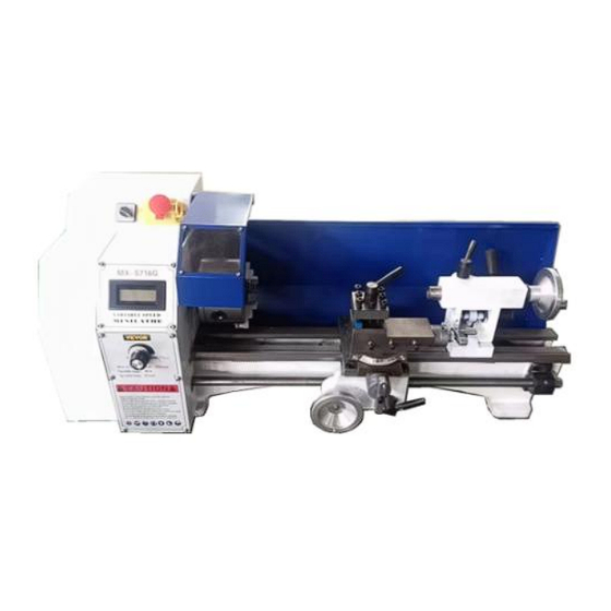
LATHE
USER MANUAL
We continue to be committed to provide you tools with competitive price.
"Save Half", "Half Price" or any other similar expressions used by us only represents an
estimate of savings you might benefit from buying certain tools with us compared to the major
top brands and doses not necessarily mean to cover all categories of tools offered by us. You
are kindly reminded to verify carefully when you are placing an order with us if you are
actually saving half in comparison with the top major brands.
Advertisement
Table of Contents

Subscribe to Our Youtube Channel
Related Manuals for VEVOR MX-S716G


Summary of Contents for VEVOR MX-S716G
- Page 1 Technical Support and E-Warranty Certificate www.vevor.com/support LATHE USER MANUAL We continue to be committed to provide you tools with competitive price. "Save Half", "Half Price" or any other similar expressions used by us only represents an estimate of savings you might benefit from buying certain tools with us compared to the major top brands and doses not necessarily mean to cover all categories of tools offered by us.
- Page 3 CustomerService@vevor.com This is the original instruction, please read all manual instructions carefully before operating. VEVOR reserves a clear interpretation of our user manual. The appearance of the product shall be subject to the product you received. Please forgive us that we won't inform you again if there are any technology or software updates on our product.
- Page 4 Matters needing attention: The information contained in this handbook is intended as a guide to the operation of these machines and does form part contract. data contains been obtained from machine manufacturer and from other sources. Whilst every effort has been made to ensure the accuracy of these transcriptions it would be impracticable to verify each and every item.
-
Page 5: Symbol Guide
Our company reserves the right to make changes to this specification and product specifications. We will make continuous efforts to improve the quality of our products. All rights reserved. Reproduction or reproduction is not allowed without permission. SYMBOL GUIDE Symbol Symbol Description Warning - To reduce the risk of injury, user must read instructions manual carefully. - Page 6 Do not put hands into safety guard when machine is working To signify that the mains plug must be disconnected from electrical outlet for the purposes of maintenance of electrical equipment, in the case of malfunction or when left unattended To signify that safety footwear must be worn To signify that protective gloves must be worn To signify that head protection must be worn...
-
Page 7: Safety Information
SAFETY INFORMATION Warning!Read all safety warnings, instructions, illustrations and specifications provided with this machine. Failure to follow all instructions listed below may result in electric shock, fire and/or serious injury. Save all warnings and instructions for future reference. Workspace Safety Keep the work area clean and well-lit. - Page 8 Personal Safety DO NOT use this device while you are tired or under the influence of drugs, alcohol, or medication. Always wear appropriate personal protective equipment, such as a dust mask, a hard hat, goggles, nonskid safety shoes, and earplugs when using this machine.
- Page 9 before further use. Maintain tools with care. Keep cutting tools sharp and clean. Service for this device must be performed only by qualified repair personnel. Store this device and its components out of reach of children and other ...
-
Page 10: Specifications
SPECIFICATIONS Technical parameter: Model MX-S716G Drive Type Direct drive motor, no belt drive, Metal gear 220V-240V/50 Hz Input Power 220V-240V/50 Hz 110V/60 Hz Rated Power 800W Wood, Plastics, Soft Metals (Brass, Copper, Material Compatibility Aluminium, etc.) Swing over Bed 200 mm... -
Page 11: Package List
PACKAGE LIST Unpacking Carefully unpack the mini lathe and check all items. Do not discard any packing material until the machine is fully assembled and operational. If any parts are missing or broken, please contact us. - 9 -... - Page 12 Name Qty. Mini lathe Screwdrivers Chuck Key Spanners Chuck Jaws Metal Gears Oil Can Allen Keys Dead Centre Tool Box Instruction Manual - 10 -...
-
Page 13: Unpacking And Cleaning
UNPACKING AND CLEANING 1. Finish removing the wooden crate from around the lathe 2. Check all the accessories of the machine tool according to the packing list. 3. Unbolt the lathe from the shipping crate bottom. 4. Choose a location for the lathe that is dray, has good lighting and has enough room to be able to service the lathe on all four sides. - Page 14 removing their nuts and subsequently removing the chuck. Tapping the chuck with a soft mallet might be required. To place a new chuck onto the spindle, follow the above steps in reverse order. Jaw Replacement: Place the chuck key into the chuck hole and rotate ...
-
Page 15: Operation
Quill Locking: Rotate the lever clockwise to lock the spindle and anti-clockwise to unlock. Tail Feed Adjustment: Rotate the tail feed handwheel clockwise to advance the tailstock towards the chuck. Rotate the handwheel anti-clockwise to move the tailstock away from the chuck OPERATION 1. - Page 16 Caution: carriage lock screw must be UN locked before engaging automatic feeds or damage to lathe may occur. 6. Longitudinal Traverse Handwheel Rotate handwheel clockwise to move the apron assembly toward the tailstock (right). Rotate the hand wheel counter-clockwise to move the apron assembly to ward the Headstock(left).
- Page 17 11. tailstock Clamping screw Turn hex nut clockwise to lock and counter-clockwise to unlock. 12. tailstock Quill Clamping Lever Rotate the lever clockwise to lock the spindle and counter-clockwise to unlock. 13. tailstock Quill Traverse Handwheel Rotate clockwise to advance the quill. Rotate counter-clockwise to retract the quill.
- Page 18 OPERATION Replacement of Chuck The head spindle holding fixture is cylindrical. Loose three set screws and nuts (A, Fig. 13 only two are shown)on the la the chuck flange to remove the chuck. Position the new chuck and fix it using the same set screws and nuts.
- Page 19 Longitudinal Turning with Auto Feed: Use the table(A,Fig.18) on the lathe for selecting the feed speed or the thread pitch. Adjust the change gear if there quired feed or thread pitch that can not be obtained with the installed gear set.
-
Page 20: Wiring Diagram
WIRING DIAGRAM Ammeter Ground Line Motor Integrated Circuit Load Wire Connector Neutral Wire Fuse WARNING! Connection of the lathe and all other electrical work may only be carried out by an authorized electrician! Failure to comply may cause serious injury and damage to the machinery and property! - 18 -... -
Page 21: Maintenance
The MX-S716G Lathe is rated at 800W. Confirm power available at the lathe' s location is the same rating as the lathe. Using the wiring diagram for connecting the lathe to the mains supply. Make sure the lathe is properly grounded. -
Page 22: Troubleshooting
cuts due to sharp-edged chips. Never use flammable solvents or cleaning agents or agents that generate noxious fumes! Protect electrical components, such as motors, switches, switch boxes, etc., against humidity when cleaning. 4. After the operation every day, eliminate all the chips and clean different parts of the machine tool and apply machine tool oil to prevent rusting. - Page 23 Adjust the workpiece’s diameter. Adjust the tailstock to the centre of the The workpiece becomes workpiece. conned. Align the top slide properly. Reduce the feed rate. The lathe is chattering. Tighten the main bearing. Increase the clearance angle. Flank wear is too high. Properly centre the cutting tool onto the workpiece.
- Page 24 Technical Support and E-Warranty Certificate www.vevor.com/support...
Need help?
Do you have a question about the MX-S716G and is the answer not in the manual?
Questions and answers
I have purched your four jaw chuck to use on this MX - S716G machine. Can you offer instructions as how to change the back plate?
To change the back plate on a VEVOR MX-S716G machine with a four jaw chuck:
1. Remove the chuck by first unscrewing the nuts, then removing the chuck itself. You may need to tap the chuck gently with a soft mallet.
2. Once the chuck is removed, the back plate can be accessed and replaced as needed.
3. To install a new chuck, reverse the removal steps—align the chuck on the spindle and secure it with the nuts. Make sure everything is properly tightened.
Note: The specific process for removing the back plate itself is not detailed, but it is implied to be part of the chuck removal process.
This answer is automatically generated