
Related Manuals for Raymarine RSW-Wired


Summary of Contents for Raymarine RSW-Wired
- Page 1 RSW-Wired Smart Performance Wind Transducer & Gateway INSTALLATION INSTRUCTIONS English (en-US) Date: 09-2023 Document number: 87465 (Rev 1) © 2023 Raymarine UK Limited...
- Page 3 Trademark and patents notice Raymarine, Tacktick, Pathfinder, ClearPulse, Truzoom, SeaTalk , SeaTalk , SeaTalkng , and Micronet, are registered or claimed trademarks of Raymarine Belgium. FLIR, Fishidy, Fishing Hot Spots, YachtSense , DockSense, LightHouse, RangeFusion, DownVision, SideVision, RealVision, HyperVision, Dragonfly, Element, Quantum, Axiom, Instalert, Infrared Everywhere, The World’s Sixth Sense and ClearCruise are registered or claimed trademarks of FLIR...
-
Page 5: Table Of Contents
CONTENTS CHAPTER 1 IMPORTANT INFORMATION ......7 Parts supplied ...............17 Safety warnings ................7 Additional components ..........17 Product warnings ............... 7 CHAPTER 5 PRODUCT DIMENSIONS........18 Regulatory notices ..............7 Product dimensions — Wind transducer ....19 Disclaimer ................7 Product dimensions — Gateway ......... - Page 6 SeaTalkng ® power cables ..........31 SeaTalkng ® product loading ..........31 CHAPTER 15 TECHNICAL SUPPORT........52 SeaTalkng ® power connection point ......32 Raymarine product support and servicing 15.1 ....53 SeaTalkng ® system loading ..........32 Viewing product information ........54 Power distribution — SeaTalkng ®...
-
Page 7: Chapter 1 Important Information
There are no user serviceable Raymarine does not warrant that this product is error-free or that it is parts or adjustments. The operator should never remove the compatible with products manufactured by any person or entity other than cover or attempt to service the product. -
Page 8: Warranty Registration
Raymarine UK Limited does not exclude Raymarine UK Limited’s liability www.raymarine.com/en-gb/policies/recycling (if any) to you for personal injury or death resulting from Raymarine UK Limited’s negligence, for fraud or for any matter which it would be illegal to exclude or to attempt to exclude. -
Page 9: Chapter 2 Document Information
CHAPTER 2: DOCUMENT INFORMATION CHAPTER CONTENTS • 2.1 Applicable products — page 10 • 2.2 Document information — page 10 • 2.3 Document conventions — page 10 • 2.4 Document illustrations — page 10 • 2.5 Product documentation — page 10 •... -
Page 10: Applicable Products
Procedures for performing specific tasks using the product’s user interface. • 87459 — RSW-Wired Wind Transducer & Smart Wind Wired Gateway Mounting Template The term “Select” is used to refer to the action of: • Touchscreen control — using your finger to select a menu option or item These and other Raymarine product documents are available to download on the screen. -
Page 11: Operation Instructions
• Raymarine user manuals are also available to download free-of-charge from the Raymarine® website, in the popular PDF format. These PDF files can be viewed on a PC / laptop, tablet, smartphone, or on the latest generation of Raymarine®... -
Page 12: Chapter 3 Product And System Overview
CHAPTER 3: PRODUCT AND SYSTEM OVERVIEW CHAPTER CONTENTS • 3.1 Product overview — page 13 • 3.2 Smart Wind Transducer compatibility — page 13 • 3.3 System example — page 14... -
Page 13: Product Overview
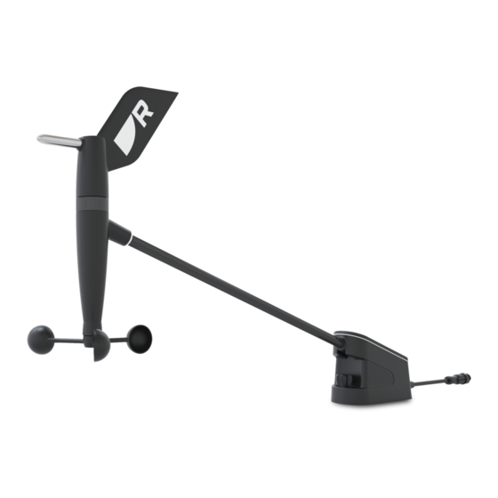
3.1 Product overview • Precision design for increased accuracy. • Lightweight arm design with rigid carbon construction. The RSW-Wired is a short arm Smart Wind transducer system designed for • NMEA 2000 wired gateway included, for connection to SeaTalkng or performance sailors. -
Page 14: System Example
Displaying mast rotation angle data In order to display mast rotation angle data, the following Raymarine® devices must be available on the network: • Axiom multifunction display, running LightHouse™ 4 version 4.5 or later. - Page 15 9. MFD/Charplotter (e.g.: Axiom® 2 Pro), running LightHouse™ 4 version 4.5 or later. Note: In order for your connected Multifunction display / Chartplotter to calculate and display true wind values, your vessel’s Speed Through Water (STW) (received from a speed transducer) and Heading (received from a heading sensor) data must be available.
-
Page 16: Chapter 4 Parts Supplied
CHAPTER 4: PARTS SUPPLIED CHAPTER CONTENTS • 4.1 Parts supplied — page 17... -
Page 17: Parts Supplied
40 mm (1.57 in) heat shrink tube (required to insulate ground wire when shortening the mast cable). Ring crimp terminal (required for additional ground connection when the gateway is not mounted on a metal surface). Mast cable, 30 m (98.43 ft) reel. Documentation. RSW-Wired Smart Wind transducer. Parts supplied... -
Page 18: Chapter 5 Product Dimensions
CHAPTER 5: PRODUCT DIMENSIONS CHAPTER CONTENTS • 5.1 Product dimensions — Wind transducer — page 19 • 5.2 Product dimensions — Gateway — page 19... -
Page 19: Product Dimensions - Wind Transducer
5.1 Product dimensions — Wind transducer 5.2 Product dimensions — Gateway Item Description 14.70 mm (0.58 in) 176.80 mm (6.96 in) 137.98 mm (5.43 in) Item Description 155.61 mm (6.13 in) 186.22 mm (7.33 in) 47.83 mm (1.88 in) 540.712 mm (21.29 in) 30.61 mm (1.21 in) 104.26 mm (4.10 in) 118.50 mm (4.67 in) -
Page 20: Chapter 6 Location Requirements
CHAPTER 6: LOCATION REQUIREMENTS CHAPTER CONTENTS • 6.1 Warnings and cautions — page 21 • 6.2 Wind transducer location requirements — page 21 • 6.3 Gateway location requirements — page 21... -
Page 21: Warnings And Cautions
6.1 Warnings and cautions • Damage — Install the product in a location where it will be protected from physical damage and vibration. Important: • Mounting surface — Ensure the product is adequately supported on a secure surface. Do not mount the product or cut holes in places which may Before proceeding, ensure that you have read and understood the damage the structure of the vessel. -
Page 22: Chapter 7 Installation
CHAPTER 7: INSTALLATION CHAPTER CONTENTS • 7.1 Tools required — page 23 • 7.2 Mast cable routing — page 23 • 7.3 Removing the mounting plate — page 24 • 7.4 Mounting the wind transducer — page 24 • 7.5 Mounting the gateway — page 25... -
Page 23: Tools Required
4 mm ⁄ in) drill bit should be used when mounting the wind transducer on an aluminium surface). RSW-Wired Smart wind transducer. 2. Cable routing externally. 3. Cable routing internally. Installation... -
Page 24: Removing The Mounting Plate
4. Mast. • Ensure that the provided fixings are suitable for the mounting surface material and thickness. 5. Deck. 6. Gateway. Bulkhead. 7.3 Removing the mounting plate The wind transducer is supplied with the mounting plate fitted. The mounting plate must be removed before installation. 1. -
Page 25: Mounting The Gateway
5. Position the wind transducer over the mounting plate, ensuring the tabs on the rear of the mounting plate are inserted into the recesses on the rear of the wind transducer base. 6. Push the wind transducer forward and down onto the mounting plate. 7. - Page 26 Important: • If the gateway is being mounted on a metal surface which is already grounded, the fixing screw will act as the ground connection. • If you are not mounting the gateway (for example, the gateway is floating, or cable tied to an existing vessel wiring loom), the ring crimp terminal of the ground wire should be connected to the gateway using a suitable nut and bolt (not supplied).
-
Page 27: Chapter 8 Cables And Connections - General Information
CHAPTER 8: CABLES AND CONNECTIONS — GENERAL INFORMATION CHAPTER CONTENTS • 8.1 General cabling guidance — page 28 • 8.2 Connections overview — page 29 • 8.3 Connecting cables — page 29 Cables and connections — General information... -
Page 28: General Cabling Guidance
– High current carrying AC and DC power lines. • Unless otherwise stated only use cables supplied by Raymarine. – Antennas. • Where it is necessary to use non-Raymarine cables, ensure that they are of correct quality and gauge for their intended purpose. (e.g.: longer power Strain relief cable runs may require larger wire gauges to minimize voltage drop along the run). -
Page 29: Connections Overview
8.2 Connections overview 8.3 Connecting cables The wind transducer connects to the SeaTalkng ® / NMEA 2000 network Follow the steps below to connect the cable(s) to your product. using the supplied adaptor cable and gateway. 1. Ensure that the vessel's power supply is switched off. 2. -
Page 30: Chapter 9 Power Connection
CHAPTER 9: POWER CONNECTION CHAPTER CONTENTS • 9.1 SeaTalkng ® power supply — page 31 • 9.2 SeaTalkng ® power cables — page 31 • 9.3 SeaTalkng ® product loading — page 31 • 9.4 SeaTalkng ® power connection point — page 32 •... -
Page 31: Seatalkng ® Power Supply
9.1 SeaTalkng ® power supply 9.2 SeaTalkng ® power cables Your product is supplied power via the SeaTalkng ® backbone. The following SeaTalkng ® power cables can be used to connect the backbone to your chosen power supply: A SeaTalkng ® backbone requires a single 12 V dc power supply. Power can be supplied to the SeaTalkng ®... -
Page 32: Seatalkng ® Power Connection Point
Products which have a dedicated power supply connection that are connected to the SeaTalkng ® backbone will still have an LEN rating. This is because product’s SeaTalkng ®/NMEA 2000 internal transceiver will still be powered by the SeaTalkng ® backbone. LENs are used to determine the power connection point for the SeaTalkng ®... -
Page 33: Power Distribution - Seatalkng
It covers common vessel power arrangements, but does NOT cover every scenario. If you are unsure how to provide the correct level of protection, please consult an authorized Raymarine dealer or a suitably qualified professional marine electrician. Implementation — connection to distribution panel... - Page 34 3. Connection point for drain wire. Important: Battery connection scenario A: Observe the recommended fuse / breaker ratings provided in the product’s documentation, however be aware that the suitable fuse / breaker rating is Suitable for a vessel with a common RF ground point. In this scenario, the dependent on the number of devices being connected.
-
Page 35: Power Connection Via Autopilot Control Unit (Acu)
2. Power switch for SeaTalkng ® power supply (Must be switched [ON] to The SeaTalkng ® backbone can be supplied 12 V dc power from a compatible provide power to the SeaTalkng ® backbone. Raymarine Autopilot Control Unit (ACU). 3. ACU / SPX autopilot to SeaTalkng spur cable (part number: R12112). Important: The SeaTalkng ®... -
Page 36: Chapter 10 Ground Connection
CHAPTER 10: GROUND CONNECTION CHAPTER CONTENTS • 10.1 Gateway ground connection — page 37... -
Page 37: Gateway Ground Connection
10.1 Gateway ground connection The gateway must have a ground connection to the to the vessel’s RF ground point, where no RF ground is available connect to the vessel’s negative (–) battery supply. The top fixing hole in the gateway is used for the ground connection point. There are 3 options for the ground connection. -
Page 38: Chapter 11 Connections
CHAPTER 11: CONNECTIONS CHAPTER CONTENTS • 11.1 Connecting the wind transducer — page 39 • 11.2 Cutting the cable — page 39 • 11.3 Connecting mast cable to the gateway — page 39 • 11.4 Connecting the gateway to the network — page 40... -
Page 39: Connecting The Wind Transducer
11.1 Connecting the wind transducer 11.2 Cutting the cable Follow the steps below to connect the wind transducer’s cable to the Once the cable has been fully routed, if desired, any excess cable can be cut connector on the supplied mast cable. off and the wires prepared for connection to the gateway. -
Page 40: Connecting The Gateway To The Network
Important: To prevent water ingress, the gateway’s cover MUST be fitted in all installations. 11.4 Connecting the gateway to the network The gateway must be connected to a SeaTalkng ® / NMEA 2000 network. 1. Feed the bare-ended wires and cable insulation/sheath through the cable seal. -
Page 41: Chapter 12 Configuration
CHAPTER 12: CONFIGURATION CHAPTER CONTENTS • 12.1 RSW series wind transducer configuration — page 42 • 12.2 Configuring RSW wind using LightHouse 4 display — page 42 • 12.3 Configuring RSW wind using i70/i70s instrument display — page 43 Configuration... -
Page 42: Rsw Series Wind Transducer Configuration
12.1 RSW series wind transducer configuration Rotating mast example The RSW series of wind transducers requires configuration to ensure readings are presented relative to vessel heading. On a non-rotating mast where a heading sensor is present, the wind transducer will automatically compensate for any offset between installation angle and vessel centerline (heading). -
Page 43: Configuring Rsw Wind Using I70/I70S Instrument Display
• The offset should be measured from the mast’s centerline to the transducer. This may be different from the vessel centerline. 12.3 Configuring RSW wind using i70/i70s 4. If your vessel does not have a rotating mast and does not have a heading instrument display sensor;... - Page 44 The RSW wind transducer configuration is initiated from the [Transducer Set-up] menu: [Menu > Set-up > Transducer Set-up] 1. Select [Continue] to search for connected transducers. 2. Select your RSW wind transducer from the list. 3. If your vessel has a rotating mast: i.
-
Page 45: Chapter 13 Maintenance
CHAPTER 13: MAINTENANCE CHAPTER CONTENTS • 13.1 Service and maintenance — page 46 Maintenance... -
Page 46: Service And Maintenance
13.1 Service and maintenance This product contains no user serviceable components. Please refer all maintenance and repair to authorized Raymarine dealers. Unauthorized repair may affect your warranty. Warning: High voltage This product contains high voltage. Do NOT remove covers or attempt to access internal components, unless specifically instructed in the documentation provided. -
Page 47: Chapter 14 Troubleshooting
CHAPTER 14: TROUBLESHOOTING CHAPTER CONTENTS • 14.1 Troubleshooting — page 48 • 14.2 Wind data troubleshooting — page 48 • 14.3 LED diagnostic guidance — page 49 • 14.4 LED diagnostics — page 50 Troubleshooting... -
Page 48: Troubleshooting
(STW) data available. 2. If wind data appears, and you Before packing and shipping, all Raymarine® products are subjected to require True wind instead, check comprehensive testing and quality assurance programs. If you do experience the source of STW data. -
Page 49: Led Diagnostic Guidance
14.3 LED diagnostic guidance Your product has diagnostic LEDs which can be used to identify the unit’s status and to help troubleshoot any potential issues that may occur. The following section provides two basic examples of how to interpret the LED diagnostic patterns included in this publication. -
Page 50: Led Diagnostics
• Consider contacting your local dealer or Raymarine® Product Support; for contact details, refer to: p.53 — Raymarine product support and servicing (Green) No wind vane connected •... - Page 51 LED indication LED status and possible solutions (Green) Wind vane / Gateway updating • Normal operation — no user action is required. (No color) No power Check the vessel’s battery voltage, the condition of the battery terminals and power supply cables, ensuring connections are secure, clean and free from corrosion;...
-
Page 52: Chapter 15 Technical Support
CHAPTER 15: TECHNICAL SUPPORT CHAPTER CONTENTS • 15.1 Raymarine product support and servicing — page 53 • 15.2 Learning resources — page 54... -
Page 53: Raymarine Product Support And Servicing
Italy (Raymarine subsidiary): Raymarine offers dedicated service departments for warranty, service, and repairs. • E-Mail: support.it@raymarine.com Don’t forget to visit the Raymarine website to register your product • Tel: +39 02 9945 1001 for extended warranty benefits: https://www.raymarine.com/en- Spain (Authorized Raymarine distributor): us/support/product-registration •... -
Page 54: Viewing Product Information
Use the [Settings] menu to view hardware and software information about To get started, you will first need to contact Raymarine Product Support. If the your display, and connected products. representative considers that your support case would benefit from a remote session, you need to first ensure that your display has an active Internet connection via Wi-Fi. - Page 55 • http://www.youtube.com/user/RaymarineInc Training courses Raymarine regularly runs a range of in-depth training courses to help you make the most of your products. Visit the Training section of the Raymarine website for more information: • http://www.raymarine.co.uk/view/?id=2372 Technical support forum You can use the Technical support forum to ask a technical question about a Raymarine product or to find out how other customers are using their Raymarine equipment.
-
Page 56: Chapter 16 Technical Specification
CHAPTER 16: TECHNICAL SPECIFICATION CHAPTER CONTENTS • 16.1 Physical specification — page 57 • 16.2 Performance specification — page 57 • 16.3 Power specification — page 57 • 16.4 Environmental specification — page 58 • 16.5 Conformance specification — page 58... -
Page 57: Physical Specification
16.1 Physical specification Specification Specification Angle, and heeled at 25°, through the full Length: • Wind transducer (including cable): 657.76 mm wind speed range). (25.90 in) Measured roll, pitch, and • Static heading accuracy: ±1° (regardless • Wind transducer (excluding cable): 540.71 mm yaw (when transducer is of anemometer rotor magnet position). -
Page 58: Environmental Specification
16.4 Environmental specification Specification Operating temperature range: -25°C to +55°C (-13°F to +131°F) Storage temperature range: -30°C to +70°C (-22°F to +158°F) • Masthead: 100% Relative Humidity: • Below deck: up to 93% @ 40°C Waterproof rating: • Wind transducer: IPx6, IPx7 •... -
Page 59: Chapter 17 Spares And Accessories
CHAPTER 17: SPARES AND ACCESSORIES CHAPTER CONTENTS • 17.1 Spares — page 60 • 17.2 GNSS receiver accessories — page 60 • 17.3 Heading sensor accessories — page 61 • 17.4 Transducer accessories — page 61 • 17.5 SeaTalkng ® cables and accessories — page 62 Spares and accessories... -
Page 60: Spares
17.1 Spares 17.2 GNSS receiver accessories The following spares are available for your RSW-Wired transducer. The following Raymarine® GNSS receivers can be used in conjunction with the RSW-Wired wind transducer to output Ground wind data. GNSS Receivers: Item Part number and description R70941 —... -
Page 61: Heading Sensor Accessories
17.3 Heading sensor accessories 17.4 Transducer accessories The following Raymarine® heading sensors can be used in conjunction with The following Raymarine® speed transducers can be used in conjunction the RSW-Wired wind transducer to output Mast rotation angle data. with the RSW-Wired transducer to output accurate sailing wind and back-calculated Apparent Wind data. -
Page 62: Seatalkng ® Cables And Accessories
Speed and Temperature transducers: 1 x Spur cable 3 m (9.8 ft) (part number: A06040). Used to connect device to the SeaTalkng backbone. 2. 1 x Power cable 2 m (6.6 ft) (part number: A06049). Used to provide 12 V dc power to the SeaTalkng backbone. 3. - Page 63 4. 2 x Backbone terminators (part number: A06031). Terminators must be fitted to both ends of the SeaTalkng backbone. 5. 1 x Power cable 2 m (6.6 ft) (part number: A06049). Used to provide 12 V dc power to the SeaTalkng backbone. Evolution autopilot cable kit (part number: R70160) consists of: 1 x Power cable 2 m (6.6 ft) (part number: A06049).
- Page 64 1 x Power cable 2 m (6.6 ft) (part number: A06049). Used to provide • Spur cable 5 m (16.4 ft) (part number: A06041). 12 V dc power to the SeaTalkng backbone. 2. Elbow (right angled) to elbow (right angled) spur cable 0.4 m (1.3 ft) (part 2.
- Page 65 SeaTalkng ® adaptors and adaptor cables SeaTalkng adaptor cables are used to connect devices designed for different CAN bus backbones (e.g.: SeaTalk or DeviceNet) to the SeaTalkng backbone. Power cable (straight) 2 m (6.6 ft) (part number: A06049). 2. Elbow (right angled) power cable 2 m (6.6 ft) (part number: A06070). SeaTalkng ®...
- Page 66 5. SeaTalkng to DeviceNet (male) adaptor cables. Connect NMEA 2000 devices that use a DeviceNet connector to the SeaTalkng backbone, or connect SeaTalkng devices to an NMEA 2000 network. The following cables are available: • SeaTalkng to DeviceNet (male) adaptor cable 0.1 m (0.33 ft) (part number: A06078).
-
Page 67: Appendix A Supported Nmea 2000 Pgns
Appendix A Supported NMEA 2000 PGNs Supported standard NMEA 2000 PGNs are listed below. Raymarine and other proprietary PGNs are not listed. Note: Support for some PGNs may be restricted to a specific application. Administration PGNs • 59392 — ISO Acknowledge (Receive / Transmit) •... - Page 69 Index SeaTalkng .................... 40 Wind transducer................... 39 Connections overview................29 Contact details..................53 Accessories ..................61–62 DST transducers ...................61 SeaTalkng adaptor cables ..............65 SeaTalkng backbone cables ............... 64 Data sources .................... 14 SeaTalkng cables ................62 Diagnostics..................49, 54 SeaTalkng connectors .................
- Page 70 Wind transducer................... 24 Mounting plate SeaTalkng Removal ....................24 Adaptor cables ..................65 Backbone cables ................. 64 Connectors ..................65 Kits ....................... 62 Network length, SeaTalkng ®, See Backbone length, SeaTalkng ® LEN ....................... 31 NMEA 2000...................13–14, 67 Load equivalency number ..............31 LEN .......................
- Page 71 WEEE Directive..................8 What’s in the box ..................17 Wind transducer Configuration ................. 42, 44 Wire stripping ..................39...
- Page 74 Raymarine (UK / EU) Marine House, Cartwright Drive, Fareham, Hampshire. PO15 5RJ. United Kingdom. Tel: (+44) (0)1329 246 700 www.raymarine.co.uk Raymarine (US) 110 Lowell Road, Hudson, NH 03051. United States of America. Tel: (+1) 603-324-7900 www.raymarine.com...
Need help?
Do you have a question about the RSW-Wired and is the answer not in the manual?
Questions and answers