Raymarine RV-100 Installation Instructions
Hull / step bracket
Hide thumbs
Also See for RV-100:
- Installation instructions manual (25 pages) ,
- Installation instructions manual (46 pages)
Advertisement
Table of Contents
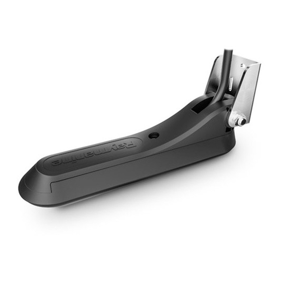
RV-100 Hull / Step Bracket
Installation instructions
Applicable products
This document is applicable to the following product:
• RV-100 3D Transducer Hull / Step Mount Bracket (A80479).
Parts supplied
The parts supplied with your product are shown below.
1.
Hull / Step bracket
2. Fixings
3. Documentation
Product dimensions - Hull / Step bracket
The transducer's dimensions including the bracket are shown
below.
Selecting a location for the Transducer
The guidelines below should be followed when selecting a
location for your transducer.
Note: The transducer is not suitable for mounting on vessels
where the transom is aft of the propeller(s).
For best performance the transducer must be installed in a
location with the least turbulence and aeration.
• The transducer should be mounted on a horizontal surface.
• Mount a suitable distance from the propeller(s) to avoid wake.
Document number: 87305-2
AB;7199;2018-01-23T15:22:58
• Turbulence can be caused by a number of other factors such
as steps (1), ribs (2), rows of rivets (3) and strakes (4). The
turbulence appears aft of these locations.
• Air trapped under the front of the vessel can travel under the
hull and appear as aeration.
• To simplify cable routing, you can choose whether to install the
transducer with the cable exiting towards the vessel's bow, or
towards the stern.
• If installing under the step on a stepped transom with the cable
exiting towards the vessel's bow, ensure sufficient room is left in
front of the bracket to allow for routing the transducer cable.
Note: Optimum transducer location and orientation (bow
cable-exit, or stern cable-exit) is dependent on hull type.
Preparing the transducer
The RV-100 RealVision™ 3D transducer (part number A80464) is
supplied already attached to a transducer hanger.
Before mounting the transducer using the accessory bracket, you
must remove the transducer from the transducer hanger.
1. Remove the bracket fixing bolt (5) and washer (6).
Store the loose parts in a safe place; you will need these parts
if you want to mount the transducer on a transom using the
standard mounting bracket in the future.
Date: 01-2018
Advertisement
Table of Contents

Subscribe to Our Youtube Channel
Related Manuals for Raymarine RV-100


Summary of Contents for Raymarine RV-100
- Page 1 Installation instructions Applicable products This document is applicable to the following product: • RV-100 3D Transducer Hull / Step Mount Bracket (A80479). Parts supplied • Air trapped under the front of the vessel can travel under the hull and appear as aeration.
- Page 2 A. Cable exiting towards the bow. B. Cable exiting towards the stern. With the transducer carrier removed from the RV-100 transducer, you can now attach the Step / Hull bracket. 1. Hold the bracket with transducer attached in position and mark the surface through the bracket’s mounting holes.
Need help?
Do you have a question about the RV-100 and is the answer not in the manual?
Questions and answers